LG 22LQ630H User manual

www.lgsolutions.com
Please read this manual carefully before operating your set and retain it
for future reference.
22LQ630H
26LQ630H
32LQ630H
P/NO : SAC34026011 (1312-REV03)
42CQ610H
OWNER’S MANUAL
LED TV / LCD TV
* LG LED TV applies LCD screen with LED backlights.
LED TV MODELS LCD TV MODELS

2
WARNING / CAUTION
WARNING/CAUTION
RISK OF ELECTRIC SHOCK
DO NOT OPEN
TO REDUCE THE RISK OF ELECTRIC SHOCK
DO NOT REMOVE COVER (OR BACK).
NO USER SERVICEABLE PARTS INSIDE.
REFER TO QUALIFIED SERVICE PERSONNEL.
WARNING/CAUTION
RISK OF ELECTRIC SHOCK
DO NOT OPEN
The lightning flash with arrowhead
symbol, within an equilateral triangle, is
intended to alert the user to the presence of
uninsulated “dangerous voltage” within the
product’s enclosure that may be of sufficient
magnitude to constitute a risk of electric shock
to persons.
WARNING/CAUTION
RISK OF ELECTRIC SHOCK
DO NOT OPEN
The exclamation point within an
equilateral triangle is intended to alert
the user to the presence of important operating
and maintenance (servicing) instructions in the
literature accompanying the appliance.
WARNING / CAUTION
To prevent fire or shock hazards, do not expose this
product to rain or moisture.
FCC NOTICE
Class B digital device
This equipment has been tested and found to comply
with the limits for a Class B digital device, pursuant to
Part 15 of the FCC Rules. These limits are designed to
provide reasonable protection against harmful
interference in a residential installation. This
equipment generates, uses and can radiate radio
frequency energy and, if not installed and used in
accordance with the instructions, may cause harmful
interference to radio communications. However, there
is no guarantee that interference will not occur in a
particular installation. If this equipment does cause
harmful interference to radio or television reception,
which can be determined by turning the equipment off
and on, the user is encouraged to try to correct the
interference by one or more of the following measures:
- Reorient or relocate the receiving antenna.
- Increase the separation between the equipment and
receiver.
- Connect the equipment to an outlet on a circuit
different from that to which the receiver is
connected.
- Consult the dealer or an experienced radio/TV
technician for help.
Any changes or modifications expressly approved
by the party responsible for compliance could void
the user’s authority to operate the equipment.
CAUTION
Do not attempt to modify this product in any way
without written authorization from LG Electronics.
Unauthorized modification could void the user’s
authority to operate this product
NOTE TO CABLE/TV INSTALLER
This reminder is provided to call the CATV system
installer’s attention to Article 820-40 of the
National Electric Code (U.S.A.). The code provides
guidelines for proper grounding and, in particular,
specifies that the cable ground shall be connected
to the grounding system of the building, as close to
the point of the cable entry as practical.
WARNING/CAUTION
TO REDUCE THE RISK OF FIRE AND ELECTRIC
SHOCK, DO NOT EXPOSE THIS PRODUCT TO
RAIN OR MOISTURE.

3
Read these instructions.
Keep these instructions.
Heed all warnings.
Follow all instructions.
1 Do not use this apparatus near water.
Antenna Lead in Wire
Antenna Discharge Unit
(NEC Section 810-20)
Grounding Conductor
(NEC Section 810-21)
Ground Clamps
Power Service Grounding
Electrode System (NEC
Art 250, Part H)
Ground Clamp
Electric Service
Equipment
Short-circuit
Breaker
Power
Supply
NEC: National Electrical Code
2 Clean only with a dry cloth.
Antenna Lead in Wire
Antenna Discharge Unit
(NEC Section 810-20)
Grounding Conductor
(NEC Section 810-21)
Ground Clamps
Power Service Grounding
Electrode System (NEC
Art 250, Part H)
Ground Clamp
Electric Service
Equipment
Short-circuit
Breaker
Power
Supply
NEC: National Electrical Code
3 Do not block any ventilation openings. Install in
accordance with the manufacturer’s instructions.
Antenna Lead in Wire
Antenna Discharge Unit
(NEC Section 810-20)
Grounding Conductor
(NEC Section 810-21)
Ground Clamps
Power Service Grounding
Electrode System (NEC
Art 250, Part H)
Ground Clamp
Electric Service
Equipment
Short-circuit
Breaker
Power
Supply
NEC: National Electrical Code
4 Do not install near any heat sources such as
radiators, heat registers, stoves, or other
apparatus (including amplifiers)that produce
heat.
Antenna Lead in Wire
Antenna Discharge Unit
(NEC Section 810-20)
Grounding Conductor
(NEC Section 810-21)
Ground Clamps
Power Service Grounding
Electrode System (NEC
Art 250, Part H)
Ground Clamp
Electric Service
Equipment
Short-circuit
Breaker
Power
Supply
NEC: National Electrical Code
5 Do not defeat the safety purpose of the
polarized or grounding-type plug. A polarized
plug has two blades with one wider than the
other. A grounding type plug has two blades and
a third grounding prong, The wide blade or the
third prong are provided for your safety. If the
provided plug does not fit into your outlet,
consult an electrician for replacement of the
obsolete outlet.
Antenna Lead in Wire
Antenna Discharge Unit
(NEC Section 810-20)
Grounding Conductor
(NEC Section 810-21)
Ground Clamps
Power Service Grounding
Electrode System (NEC
Art 250, Part H)
Ground Clamp
Electric Service
Equipment
Short-circuit
Breaker
Power
Supply
NEC: National Electrical Code
6 Protect the power cord from being walked on or
pinched particularly at plugs, convenience
receptacles, and the point where they exit from
the apparatus.
Antenna Lead in Wire
Antenna Discharge Unit
(NEC Section 810-20)
Grounding Conductor
(NEC Section 810-21)
Ground Clamps
Power Service Grounding
Electrode System (NEC
Art 250, Part H)
Ground Clamp
Electric Service
Equipment
Short-circuit
Breaker
Power
Supply
NEC: National Electrical Code
7 Only use attachments/accessories specified by
the manufacturer.
Antenna Lead in Wire
Antenna Discharge Unit
(NEC Section 810-20)
Grounding Conductor
(NEC Section 810-21)
Ground Clamps
Power Service Grounding
Electrode System (NEC
Art 250, Part H)
Ground Clamp
Electric Service
Equipment
Short-circuit
Breaker
Power
Supply
NEC: National Electrical Code
8 Use only with the cart, stand, tripod, bracket, or
table specified by the manufacturer, or sold with
the apparatus. When a cart is used, use caution
when moving the cart/apparatus combination to
avoid injury from tip-over.
Antenna Lead in Wire
Antenna Discharge Unit
(NEC Section 810-20)
Grounding Conductor
(NEC Section 810-21)
Ground Clamps
Power Service Grounding
Electrode System (NEC
Art 250, Part H)
Ground Clamp
Electric Service
Equipment
Short-circuit
Breaker
Power
Supply
NEC: National Electrical Code
9 Unplug this apparatus during lighting storms or
when unused for long periods of time.
Antenna Lead in Wire
Antenna Discharge Unit
(NEC Section 810-20)
Grounding Conductor
(NEC Section 810-21)
Ground Clamps
Power Service Grounding
Electrode System (NEC
Art 250, Part H)
Ground Clamp
Electric Service
Equipment
Short-circuit
Breaker
Power
Supply
NEC: National Electrical Code
10 Refer all servicing to qualified service personnel.
Servicing is required when the apparatus has
been damaged in any way, such as power-supply
cord or plug is damaged, liquid has been spilled
or objects have fallen into the apparatus, the
apparatus has been exposed to rain or moisture,
does not operate normally, or has been dropped.
Antenna Lead in Wire
Antenna Discharge Unit
(NEC Section 810-20)
Grounding Conductor
(NEC Section 810-21)
Ground Clamps
Power Service Grounding
Electrode System (NEC
Art 250, Part H)
Ground Clamp
Electric Service
Equipment
Short-circuit
Breaker
Power
Supply
NEC: National Electrical Code
SAFETY INSTRUCTIONS
IMPORTANT SAFETY INSTRUCTIONS
Antenna Lead in Wire
Antenna Discharge Unit
(NEC Section 810-20)
Grounding Conductor
(NEC Section 810-21)
Ground Clamps
Power Service Grounding
Electrode System (NEC
Art 250, Part H)
Ground Clamp
Electric Service
Equipment
Short-circuit
Breaker
Power
Supply
NEC: National Electrical Code

4
the TV with wet hands. Do not install this
product near flammable objects such as
gasoline or candles or expose the TV to direct
air conditioning.
Antenna Lead in Wire
Antenna Discharge Unit
(NEC Section 810-20)
Grounding Conductor
(NEC Section 810-21)
Ground Clamps
Power Service Grounding
Electrode System (NEC
Art 250, Part H)
Ground Clamp
Electric Service
Equipment
Short-circuit
Breaker
Power
Supply
NEC: National Electrical Code
18 Do not expose to dripping or splashing and do
not place objects filled with liquids, such as
vases, cups, etc. on or over the apparatus (e.g.
on shelves above the unit).
Antenna Lead in Wire
Antenna Discharge Unit
(NEC Section 810-20)
Grounding Conductor
(NEC Section 810-21)
Ground Clamps
Power Service Grounding
Electrode System (NEC
Art 250, Part H)
Ground Clamp
Electric Service
Equipment
Short-circuit
Breaker
Power
Supply
NEC: National Electrical Code
19 GROUNDING
(Except for devices which are not grounded.)
Ensure that you connect the earth ground wire
to prevent possible electric shock. (i.e. a TV
with a three-prong grounded AC plug must be
connected to a three-prong grouned AC
outlet) If grounding methods are not possible,
have a qualified electrician install a separate
circuit breaker.
Do not try to ground the unit by connecting it
to telephone wires, lightening rods, or gas
pipes.
Antenna Lead in Wire
Antenna Discharge Unit
(NEC Section 810-20)
Grounding Conductor
(NEC Section 810-21)
Ground Clamps
Power Service Grounding
Electrode System (NEC
Art 250, Part H)
Ground Clamp
Electric Service
Equipment
Short-circuit
Breaker
Power
Supply
NEC: National Electrical Code
20 DISCONNECTING DEVICE FROM MAINS
Mains plug is the disconnecting device.
The plug must remain readily operable.
21 As long as this unit is connected to the AC wall
outlet, it is not disconnected from the AC
power source even if you turn off this unit by
SWITCH.
Do not attempt to modify this product in any
way without written authorization from LG
Electronics. Unauthorized modification could
void the user’s authority to operate this prod-
uct.
22 ANTENNAS
Outdoor antenna grounding
If an outdoor antenna is installed, follow the
precautions below. An outdoor antenna system
should not be located in the vicinity of
overhead power lines or other electric light or
power circuits, or where it can come in contact
with such power lines or circuits as death or
serious injury can occur.
Be sure the antenna system is grounded so as
11 Never touch this apparatus or antenna during
a thunder or lighting storm.
12 When mounting a TV on the wall, make sure
not to install the TV by the hanging power and
signal cables on the back of the TV.
13 Do not allow an impact shock or any objects to
fall into the product, and do not drop onto the
screen.
14 Keep the packing anti-moisture material or
vinyl packing out of the reach of children. Anti-
moisture material is harmful if swallowed. If
swallowed by mistake, force the patient to
vomit and visit the nearest hospital. Additionally,
vinyl packing can cause suffocation. Keep it out
of the reach of children.
15 CAUTION concerning the Power Cord :
It is recommend that appliances be placed
upon a dedicated circuit; that is, a single outlet
circuit which powers only that appliance and
has no additional outlets or branch circuits.
Check the specification page of this owner's
manual to be certain.
Do not connect too many appliances to the
same AC power outlet as this could result in
fire or electric shock.
Do not overload wall outlets. Overloaded wall
outlets, loose or damaged wall outlets,
extension cords, frayed power cords, or
damaged or cracked wire insulation are
dangerous. Any of these conditions could
result in electric shock or fire. Periodically
examine the cord of your appliance, and if its
appearance indicates damage or deterioration,
unplug it, discontinue use of the appliance, and
have the cord replaced with an exact
replacement part by an authorized servicer.
Protect the power cord from physical or
mechanical abuse, such as being twisted,
kinked, pinched, closed in a door, or walked
upon. Pay particular attention to plugs, wall
outlets, and the point where the cord exits the
appliance.
Do not move the TV with the power cord
plugged in. Do not use a damaged or loose
power cord. Be sure do grasp the plug when
unplugging the power cord. Do not pull on the
power cord to unplug the TV.
Antenna Lead in Wire
Antenna Discharge Unit
(NEC Section 810-20)
Grounding Conductor
(NEC Section 810-21)
Ground Clamps
Power Service Grounding
Electrode System (NEC
Art 250, Part H)
Ground Clamp
Electric Service
Equipment
Short-circuit
Breaker
Power
Supply
NEC: National Electrical Code
16 Do not stick metal objects or any other con-
ductive material into the power cord. Do not
touch the end of the power cord while it is
plugged in.
17 WARNING - To reduce the risk of fire or
electrical shock, do not expose this product to
rain, moisture or other liquids. Do not touch

5
to provide some protection against voltage
surges and built-up static charges.
Section 810 of the National Electrical Code
(NEC) in the U.S.A. provides information with
respect to proper grounding of the mast and
supporting structure, grounding of the lead-in
wire to an antenna discharge unit, size of
grounding conductors, location of antenna
discharge unit, connection to grounding
electrodes and requirements for the grounding
electrode.
Antenna grounding according to the
National Electrical Code, ANSI/NFPA 70
Antenna Lead in Wire
Antenna Discharge Unit
(NEC Section 810-20)
Grounding Conductor
(NEC Section 810-21)
Ground Clamps
Power Service Grounding
Electrode System (NEC
Art 250, Part H)
Ground Clamp
Electric Service
Equipment
Short-circuit
Breaker
Power
Supply
NEC: National Electrical Code
23 Cleaning
When cleaning, unplug the power cord and
scrub gently with a soft cloth to prevent
scratching. Do not spray water or other liquids
directly on the TV as electric shock may occur.
Do not clean with chemicals such as alcohol,
thinners or benzene.
24 Moving
Make sure the product is turned off, unplugged
and all cables have been removed. It may take
2 or more people to carry larger TVs. Do not
press against or put stress on the front panel
of the TV.
25 Ventilation
Install your TV where there is proper
ventilation. Do not install in a confined space
such as a bookcase. Do not cover the product
with cloth or other materials (e.g.) plastic while
plugged in. Do not install in excessively dusty
places.
26 If you smell smoke or other odors coming from
the TV, unplug the power cord contact and
authorized service center.
27 Do not press strongly upon the panel with a
hand or sharp object such as nail, pencil or pen,
or make a scratch on it.
Antenna Lead in Wire
Antenna Discharge Unit
(NEC Section 810-20)
Grounding Conductor
(NEC Section 810-21)
Ground Clamps
Power Service Grounding
Electrode System (NEC
Art 250, Part H)
Ground Clamp
Electric Service
Equipment
Short-circuit
Breaker
Power
Supply
NEC: National Electrical Code
28 Keep the product away from direct sunlight.
29 Dot Defect
The Plasma or LCD panel is a high technology
product with resolution of two million to six
million pixels. In a very few cases, you could see
fine dots on the screen while you’re viewing the
TV. Those dots are deactivated pixels and do
not affect the performance and reliability of
the TV.
30 Generated Sound
“Cracking” noise: A cracking noise that occurs
when watching or turning off the TV is
generated by plastic thermal contraction due
to temperature and humidity. This noise is
common for products where thermal
deformation is required.
Electrical circuit humming/panel buzzing: A low
level noise is generated from a high-speed
switching circuit, which supplies a large amount
of current to operate a product. It varies
depending on the product.
This generated sound does not affect the
performance and reliability of the product.
31 Take care not to touch the ventilation
openings. When watching the TV for a long
period, the ventilation openings may become
hot.
32 If the TV feels cold to the touch, there may be
a small “flicker” when it is turned on. This is
normal, there is nothing wrong with TV.
Some minute dot defects may be visible on the
screen, appearing as tiny red, green, or blue
spots. However, they have no adverse effect on
the monitor's performance.
Avoid touching the LCD screen or holding your
finger(s) against it for long periods of time.
Doing so may produce some temporary
distortion effects on the screen.
ON DISPOSAL
(Only Hg lamp used LCD TV)
The fluorescent lamp used in this product
contains a small amount of mercury. Do not
dispose of this product with general
household waste. Disposal of this product
must be carried out in accordance to the
regulations of your local authority.

6
CONTENTS
WARNING / CAUTION ............... 2
SAFETY INSTRUCTIONS ............. 3
CONTENTS ........................... 6
FEATURES OF THIS TV............... 7
PREPARATION
Accessories ............................... 8
Protection Cover........................... 9
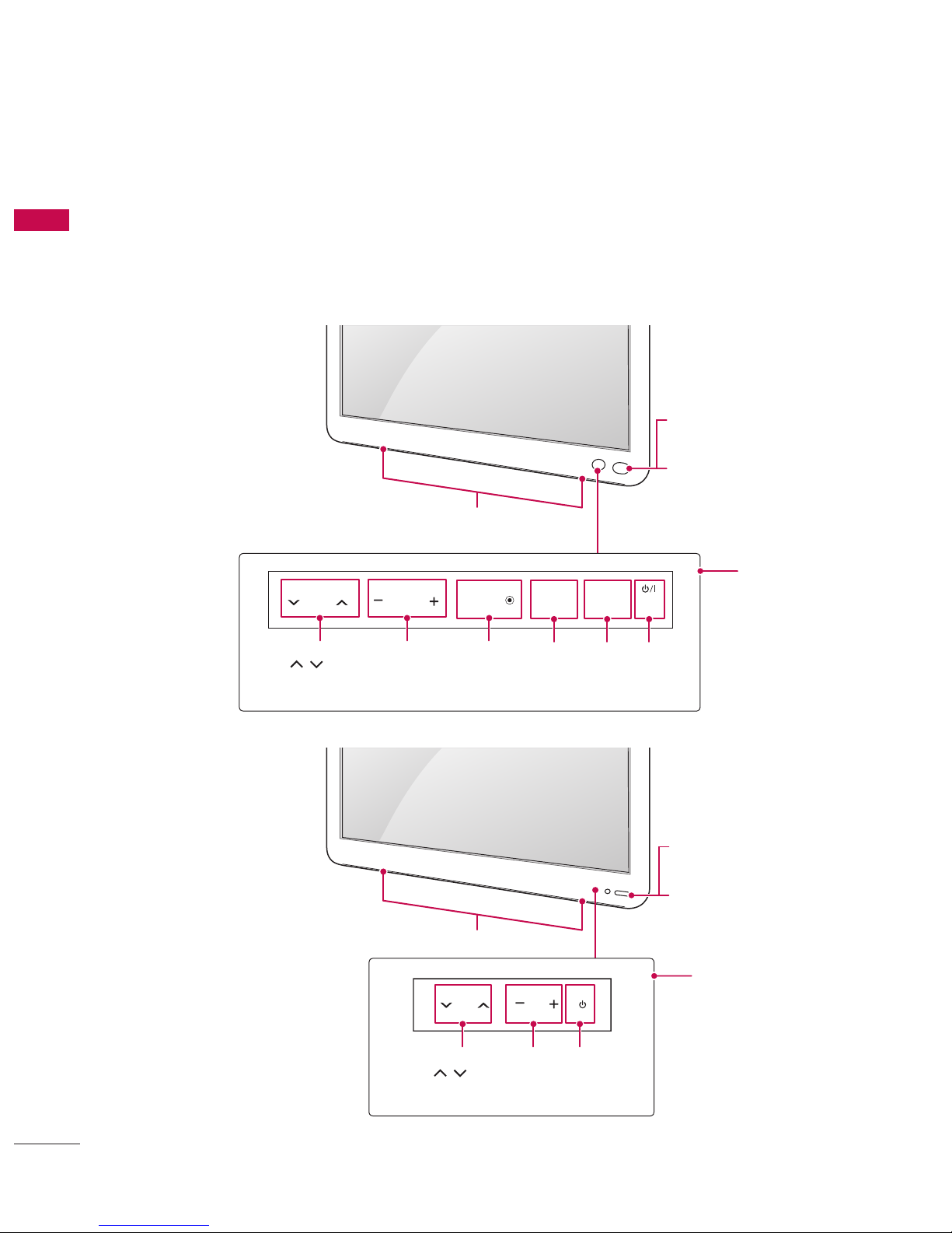
Front Panel Information. . . . . . . . . . . . . . . . . . . . 10
Back Panel Information . . . . . . . . . . . . . . . . . . . . 12
Cable Management ....................... 15
Wall Mount Installation . . . . . . . . . . . . . . . . . . . . 17
Kensington Security System . . . . . . . . . . . . . . . . 17
VESA Wall Mounting . . . . . . . . . . . . . . . . . . . . . . 18
Antenna or Cable Connection . . . . . . . . . . . . . . 19
EXTERNAL EQUIPMENT SETUP
HD Receiver Setup . . . . . . . . . . . . . . . . . . . . . . . 20
DVD Setup .............................. 22
VCR Setup .............................. 23
Other A/V Source Setup . . . . . . . . . . . . . . . . . . . 25
Pillow Speaker Setup . . . . . . . . . . . . . . . . . . . . . . 26
PC Setup................................ 27
WATCHING TV / CHANNEL CONTROL
Turning On TV ........................... 33
Channel Selection......................... 33
Volume Adjustment . . . . . . . . . . . . . . . . . . . . . . . 33
Initial Setting ............................ 34
On-Screen Menus Selection . . . . . . . . . . . . . . . . 36
Channel Setup
- Auto Scan (Auto Tuning) . . . . . . . . . . . . . . 37
- Add / Delete Channel (Manual Tuning) . . 38
- Channel Editing . . . . . . . . . . . . . . . . . . . . . . 39
Channel Label............................ 40
Input List ............................... 41
PICTURE CONTROL
Picture Size (Aspect Ratio) Control . . . . . . . . . 42
Preset Picture Settings . . . . . . . . . . . . . . . . . . . . 44
Manual Picture Adjustment - User Mode . . . . . 45
Picture Improvement Technology . . . . . . . . . . . 46
Picture Reset ............................ 48
Demo Mode ............................. 49
SOUND & LANGUAGE CONTROL
Auto Volume Leveler (Auto Volume) . . . . . . . . . 50
Clear Voice II............................. 51
Balance ................................. 52
Preset Sound Settings (Sound Mode). . . . . . . . 53
Sound Setting Adjustment - User Mode . . . . . . 54
Infinite Sound ............................55
TV Speakers On/Off Setup. . . . . . . . . . . . . . . . . 56
Audio Reset ............................. 57
Stereo/SAP Broadcast Setup . . . . . . . . . . . . . . . 58
Audio Language .......................... 59
On-Screen Menus Language Selection . . . . . . . 60
Caption Mode
- Analog Broadcasting System Captions . . . 61
- Digital Broadcasting System Captions . . . 62
- Caption Option . . . . . . . . . . . . . . . . . . . . . . 63
TIME SETTING
Clock Setting
- Auto Clock Setup . . . . . . . . . . . . . . . . . . . . 64
- Manual Clock Setup . . . . . . . . . . . . . . . . . . 65
Auto On/Off Time Setting . . . . . . . . . . . . . . . . . 66
Sleep Timer Setting . . . . . . . . . . . . . . . . . . . . . . . 67
Auto Shut-Off Setting . . . . . . . . . . . . . . . . . . . . . 67
PARENTAL CONTROL / RATINGS
Set Password & Lock System . . . . . . . . . . . . . . . 68
Channel Blocking ......................... 71
Movie & TV Rating........................ 72
Downloadable Rating. . . . . . . . . . . . . . . . . . . . . . 75
External Input Blocking . . . . . . . . . . . . . . . . . . . . 76
USB
Entry Modes ............................. 77
Movie List ............................... 79
Photo List ............................... 83
Music List................................ 87
APPENDIX
Troubleshooting.......................... 90
Maintenance ............................. 92
Product Specifications . . . . . . . . . . . . . . . . . . . . . 93
Open Source License . . . . . . . . . . . . . . . . . . . . . 94

7
FEATURES OF THIS TV
WARNING/CAUTION
RISK OF ELECTRIC SHOCK
DO NOT OPEN
IMPORTANT INFORMATION TO PREVENT
“IMAGE BURN / BURN-IN” ON YOUR TV SCREEN
V When a fixed image (e.g. logos, screen menus, video game, and computer display) is displayed on the TV for
an extended period, it can become permanently imprinted on the screen. This phenomenon is known as
“image burn” or “burn-in.” Image burn is not covered under the manufacturer’s warranty.
V In order to prevent image burn, avoid displaying a fixed image on your TV screen for a prolonged period.
V Image burn can also occur on the letterboxed areas of your TV if you use the 4:3 aspect ratio setting for an
extended period.
USB IN
SERVUCE ONLY
Manufactured under license from Dolby Laboratories.
“Dolby” and the double-D symbol are trademarks of Dolby Laboratories.
The terms HDMI and HDMI High-Definition Multimedia Interface, and the HDMI logo are trademarks or
registered trademarks of HDMI Licensing LLC in the United States and other countries.
ABOUT DIVX VIDEO: DivX® is a digital video format created by DivX, LLC, a subsidiary of Rovi Corporation.
This is an official DivX Certified® device that plays DivX video. Visit divx.com for more information and software
tools to convert your files into DivX video.
ABOUT DIVX VIDEO-ON-DEMAND: This DivX Certified® device must be registered in order to play purchased
DivX Video-on-Demand (VOD) movies. To obtain your registration code, locate the DivX VOD section in your
device setup menu. Go to vod.divx.com for more information on how to complete your registration.
“DivX Certified® to play DivX® video up to HD 1080p, including premium content.”
“DivX®, DivX Certified® and associated logos are trademarks of Rovi Corporation or its subsidiaries and are
used under license.”
“Covered by one or more of the following U.S. patents:
7,295,673; 7,460,668; 7,515,710; 7,519,274”

PREPARATION
8
PREPARATION
Check your product box for the following items. If there are any missing accessories, contact the dealer
where you purchased your product. The illustrations in this manual may differ from the actual product and
item.
ACCESSORIES
PREPARATION
(For 22/26/32LQ630H)
Quick Reference Guide Power Cord A/V Adapter Cable
(For 22/26LQ630H) (For 32LQ630H) (For 26LQ630H/42CQ610H)
Cable Holder
1 EA
(See p.15, 16)
Cable Holder
3 EA
(See p.15)
Protective Bracket and
Screw for Power Cord
(See p.15, 16)
(For 42CQ610H)
MUTE
RETURN
CC
TV
POWER
GUIDE
PORTAL
ENTER
VOL CH
1 2 3
4 5 6
7 8
0
9
FLASHBK
VCR
DVD
INPUT
MENU
INFO
i
STB
P
A
G
E
PIP SAP
PIP CH- PIP CH+
PIP SWAP
PIP INPUT
ALPHA/NUM
REMOVE
RATIO
TIMER
ABC DEF
GHI
WXYZ
TUV
PQRS
MNO
JKL
&@
.:/,
1.5V 1.5V
1.5V 1.5V
1,5Vcc 1,5Vcc
기준점
Protection Cover
(See p.9)

PREPARATION
9
PROTECTION COVER
Install the included PROTECTION COVER
over the hole for the stand.
Press the Protection cover into the TV until
you hear it click.
ὤ㨴㥄
ὤ㨴㥄
wyv{lj{pvuGjv}ly
ὤ㨴㥄
ὤ㨴㥄
wyv{lj{pvuGjv}ly
Image shown may differ from your TV.
42CQ610H
Do not use any unapproved items to ensure the safety and product life span.
Any damages or injuries by using unapproved items are not covered by the warranty.
In case of some model, the thin film on screen is a part of TV, So don’t take it off.
CAUTION
The items supplied with your product may vary depending on the model.
Gently wipe any spots on the cabinet with a polishing cloth (included with some models).
Product specifications or contents of this manual may be changed without prior notice due to upgrade of product
functions.
When using a VGA (D-sub 15-pin signal cable) PC connection, use the shielded signal interface cable with a ferrite
core to maintain standards compliance for the product.
For an optimal connection, HDMI cables and USB devices should have bezels less than 10 mm (0.39 inches) thick
and 18 mm (0.7 inches) width.
Use an extension cable that supports USB 2.0 if the USB cable or USB memory stick does not fit into your TV’s
USB port.
B
AA
B
*A 10 mm (0.39 inches)
*B 18 mm (0.7 inches)
NOTE

PREPARATION
10
PREPARATION
FRONT PANEL INFORMATION
V Image shown may differ from your TV.
V NOTE: If your TV has protection tape attached, remove the tape and then wipe the TV with a cloth,
(If a polishing cloth is included with your TV, please use it).
22LQ630H
26/32LQ630H
SPEAKER
Power indicator
Off in standby mode.
Illuminates orange when the
set is switched on.
Remote control and
intelligent sensors
CHANNEL
(
ὤ㨴㥄
,
ὤ㨴㥄
)
Buttons
VOLUME
(+, -)
Buttons
POWER
Button
Touch Buttons
CHANNEL
(
ὤ㨴㥄
,
ὤ㨴㥄
)
Buttons
VOLUME
(+, -)
Buttons
ENTER
Button
MENU
Button
INPUT
Button
POWER
Button
ENTER
CH VOL MENU INPUT
SPEAKER
Power indicator
Off in standby mode.
Illuminates orange when the
set is switched on.
Remote control and
intelligent sensors
ENTER
CH VOL MENU INPUT
Touch Buttons
CHANNEL
(
ὤ㨴㥄
,
ὤ㨴㥄
)
Buttons
VOLUME
(+, -)
Buttons
ENTER
Button
MENU
Button
INPUT
Button
POWER
Button

PREPARATION
11
CH
VOL
ENTER
INPUT
MENU
42CQ610H
CH
VOL
ENTER
INPUT
MENU
VOLUME (+, -)
Buttons
ENTER Button
INPUT Button
MENU Button
POWER Button
CHANNEL(
ὤ㨴㥄
,
ὤ㨴㥄
)
Buttons
SPEAKER
Remote Control Sensor
CH
VOL
ENTER
INPUT
MENU
Power/Standby Indicator
Off in standby mode.
Illuminates blue when the set is switched on.
NOTE
G In order to change the status of standby indicator, change Power indicator in Main menu.
!
?
!
?
! !

PREPARATION
12
PREPARATION
BACK PANEL INFORMATION
V Image shown may differ from your TV.
22LQ630H
26/32LQ630H
PILLOW SPEAKER
RGB IN (PC)
ANTENNA
IN
TV-LINK
CFG
AUDIO IN
(RGB/DVI) SPEAKER
OUT(8Ω)
CPU SERVICE
(SERVICE ONLY)
PTC SERVICE
(SERVICE ONLY)
GAME CONTROL
/ M.P.I.
/DVI
IN
IN
1 2
USB IN
VIDEO/AUDIO
AV IN
RESET
UPDATE
.1
.7.5.2.3
12
.8
11
10
13
.9.6.4
14
USB IN 1
AUDIO IN
(RGB/DVI)
AV IN
AUDIO/VIDEO
RGB IN (PC)
/DVI IN 1
IN 2
GAME CONTROL
/ M.P.I.
PILLOW SPEAKER
TV-LINK
CFG
PTC SERVICE
(SERVICE ONLY) CPU SERVICE
(SERVICE ONLY)
ANTENNA IN
Healthcare Multimedia System
RESET
UPDATE
SPEAKER OUT
(
8
)
.1
14
.3.2.4.5.6.7.8
12
11
10
.9
12
13
10

PREPARATION
13
42CQ610H
ANTENNA IN
AV IN
L/MONO
R
AUDIO
VIDEO
USB IN
PILLOW SPEAKER
RS-232C IN
(SERVICE ONLY)
AUDIO IN
(RGB/DVI)
RESET
UPDATE
PTC SERVICE
(SERVICE ONLY)
SPEAKER OUT
(8
HDMI
/DVI IN
HDMI
1
2
TV-LINK
CFG
RGB IN (PC)
GAME
CONTROL/
M.P.I
)
10
13
ANTENNA IN
AV IN
L/MONO
R
AUDIO
VIDEO
USB IN
PILLOW SPEAKER
RS-232C IN
(SERVICE ONLY)
AUDIO IN
(RGB/DVI)
RESET
UPDATE
PTC SERVICE
(SERVICE ONLY)
SPEAKER OUT
(8
HDMI
/DVI IN
HDMI
1
2
TV-LINK
CFG
RGB IN (PC)
GAME
CONTROL/
M.P.I
)
2
ANTENNA IN
AV IN
L/MONO
R
AUDIO
VIDEO
USB IN
PILLOW SPEAKER
RS-232C IN
(SERVICE ONLY)
AUDIO IN
(RGB/DVI)
RESET
UPDATE
PTC SERVICE
(SERVICE ONLY)
SPEAKER OUT
(8
HDMI
/DVI IN
HDMI
1
2
TV-LINK
CFG
RGB IN (PC)
GAME
CONTROL/
M.P.I
)
711 .915
6
.3
12
8.5
14
ANTENNA IN
AV IN
L/MONO
R
AUDIO
VIDEO
USB IN
PILLOW SPEAKER
RS-232C IN
(SERVICE ONLY)
AUDIO IN
(RGB/DVI)
RESET
UPDATE
PTC SERVICE
(SERVICE ONLY)
SPEAKER OUT
(8
HDMI
/DVI IN
HDMI
1
2
TV-LINK
CFG
RGB IN (PC)
GAME
CONTROL/
M.P.I
)
1

PREPARATION
14
PREPARATION
Jack Description
1Power Cord Socket For operation with AC power.
Caution: Never attempt to operate the TV on DC power.
2ANTENNA IN Connect over-the air signals to this jack.
3PTC SERVICE
(SERVICE ONLY)
Used for PTC software updates.
4CPU SERVICE
(SERVICE ONLY)
Used for CPU software updates.
5TV - LINK CFG Computer input for programming Free To Guest services.
6SPEAKER OUT (8Ω)For use with external speakers.
7GAME CONTROL Input port for third party game Controllers.
M. P. I. Allows VOD/PPV devices or set-top boxes to control the TV.
8PILLOW SPEAKER Used to connect to pillow speaker.
9AUDIO IN (RGB/DVI) 1/8” headphone jack for analog PC audio input.
-USB IN Used for viewing multimedia files.
qRGB IN (PC) Analog PC Connection. Uses a D-sub 15-pin cable (VGA cable).
wHDMI/DVI IN Digital Connection.
Supports HD video and Digital audio.
Accepts DVI video using an adapter or HDMI to DVI cable (not included).
eAV (Audio/Video) IN Analog composite connection. Supports standard definition video only (480i).
Used for PC/DTV audio input jack.
rUPDATE Software downloads and debug mode enable/ dis-able.
RESET Hardware reset to PTC microcontroller.
?RS-232C IN
(SERVICE ONLY)
Used for software updates.
@OPTICAL DIGITAL Connect digital audio to various types of equipment.
Connect to a Digital Audio Component.
Use an Optical audio cable.

PREPARATION
15
CABLE MANAGEMENT
1 Gather and bind the cables with the CABLE
HOLDER(S) on the TV back cover.
1 Connect the cables as necessary.
To connect additional equipment, see the
EXTERNAL EQUIPMENT SETUP section.
To help prevent the power cable from being
removed by accident, secure the power cable
with the included PROTECTIVE BRACKET /
SCREW.
PROTECTIVE BRACKET /SCREW
2 Gether and bind the cables with the CABLE
HOLDER on the TV back cover.
22LQ630H 26LQ630H
CABLE HOLDER
CABLE HOLDER
1 Gather and bind the cables with the CABLE
HOLDER(S) on the TV back cover.
32LQ630H
CABLE HOLDER

PREPARATION
16
PREPARATION
1 Connect the cables as necessary.
To connect additional equipment, see the
EXTERNAL EQUIPMENT SETUP section.
Secure the power cable with the PROTECTIVE
BRACKET/SCREW as shown.
It will help prevent the power cable from being
removed by accident.
ὤ㨴㥄
ὤ㨴㥄
ὤ㨴㥄
ὤ㨴㥄
PROTECTIVE BRACKET /SCREW
(This feature is not available for all models.)
2 Install the CABLE MANAGEMENT CLIP as
shown.
ὤ㨴㥄
ὤ㨴㥄
ὤ㨴㥄
ὤ㨴㥄
CABLE MANAGEMENT CLIP
3 Put the cables inside the CABLE
MANAGEMENT CLIP and snap it closed.
ὤ㨴㥄
ὤ㨴㥄
ὤ㨴㥄
ὤ㨴㥄
42CQ610H

PREPARATION
17
For proper ventilation, allow a clearance of 4 inches on all four sides.
- The TV is equipped with a Kensington Security System connector on the back panel. Connect the Kensington
Security System cable as shown below.
- For the detailed installation and use of the Kensington Security System, refer to the user’s guide provided with
the Kensington Security System.
For further information, contact http://www.kensington.com, the internet homepage of the Kensington com-
pany. Kensington sells security systems for expensive electronic equipment such as notebook PCs and LCD pro-
jectors.
4 inches
4 inches
4 inches 4 inches
4 inches
CAUTION
G Ensure adequate ventilation by following the clearance recommendations.
G Do not mount near or above any type of heat source.
G Do not put this product next to the patient’s bed where it can be reached by the patient.
G Install product in such a way that patients will not be able to touch this product
G This product should only be mounted on a wall.
!
?
!
?
! !
WALL MOUNT INSTALLATION
KENSINGTON SECURITY SYSTEM
V Image shown may differ from your TV.
V This feature is not available for all models.
NOTE
G The Kensington Security System is an optional accessory.
!
?
!
?
! !

PREPARATION
18
PREPARATION
Model
VESA (A * B)
ὤ㨴㥄
y~YZW sz~XWWi sz~YWWi
sz~[WWi
h~T[^snZWt
AA
BB
AA
BB
Standard
Screw Quantity Wall Mounting Bracket
(sold separately)
22LQ630H
26LQ630H 100 * 100 M4 4
LSW100B(G)
32LQ630H 200 * 100 M4 4
LSW100B(G)
42CQ610H 200 * 200 M6 4
LSW200B(G) LSW220BX
VESA WALL MOUNTING
Install your wall mount on a solid wall perpendicular to the floor. When attaching to other building materials, please
contact your nearest installer.
If installed on a ceiling or slanted wall, it may fall and result in severe personal injury.
We recommend that you use an LG brand wall mount when mounting the TV to a wall.
LG recommends that wall mounting be performed by a qualified professional installer.
NOTE
G Screw length needed depends on the wall mount used. For further information, refer to the instructions
included with the mount.
G Standard dimensions for wall mount kits are shown in the table.
G When purchasing our wall mount kit, a detailed installation manual and all parts necessary for assembly are
provided.
G Do not use screws longer then the standard dimension, as they may cause damage to the inside of the TV.
G For wall mounts that do not comply with the VESA standard screw specifications, the length of the screws
may differ depending on their specifications.
G Do not use screws that do not comply with the VESA standard screw specifications.
Do not use fasten the screws too strongly, this may damage the TV or cause the TV to a fall, leading to
personal injury. LG is not liable for these kinds of accidents.
G LG is not liable for TV damage or personal injury when a non-VESA or non specified wall mount is used or
the consumer fails to follow the TV installation instructions.
!
?
!
?
! !
CAUTION
G Do not install your wall mount kit while your TV is turned on. It may result in personal injury due to electric shock.
!
?
!
?
! !
WARNING
G To prevent injury, this apparatus must be securely attached to the wall in accordance with the installation instructions.
!
?
!
?
! !

PREPARATION
19
1. Antenna (Analog or Digital)
Wall Antenna Socket or Outdoor Antenna without a Cable Box Connection.
For optimum picture quality, adjust the direction if needed.
2. Cable
ὤ㨴㥄
Wall
Antenna
Socket
Outdoor
Antenna
(VHF, UHF)
Multi-family Dwellings/Apartments
(Connect to wall antenna socket)
RF Coaxial Wire (75Ω)
Single-family Dwellings /Houses
(Connect to wall jack for outdoor antenna)
Be careful not to bend the copper wire
when connecting the antenna.
Copper Wire
Cable
TV Wall
Jack
RF Coaxial Wire (75 Ω)
ANTENNA IN
ANTENNA IN
V To improve the picture quality in a poor signal area, please purchase a signal amplifier and install properly.
V If the antenna needs to be split for two TV’s, install a 2-Way Signal Splitter.
V If the antenna is not installed properly, contact your dealer for assistance.
ANTENNA OR CABLE CONNECTION
V To prevent damage, do not connect to the power outlet until all connections are made between the devices.

20
EXTERNAL EQUIPMENT SETUP
HD RECEIVER SETUP
V To prevent the equipment damage, never plug in any power cords until you have finished connecting all equipment.
V This part of EXTERNAL EQUIPMENT SETUP mainly uses the picture for 22LQ630H model.
This TV can receive Digital Over-the-air or Digital Cable signals without an external digital set-top box.
However, if you do receive digital signals from a digital set-top box or other digital external device, refer to the
figure as shown below.
EXTERNAL EQUIPMENT SETUP
HDMI Connection
1. How to connect
1 Connect the digital set-top box to HDMI/DVI IN 1
jack on the TV.
2 No separate audio connection is necessary.
HDMI supports both audio and video.
2. How to use
V Turn on the digital set-top box.
(Refer to the owner’s manual for the digital set-top box.)
V Select HDMI 1 or HDMI 2 input source with using the
INPUT button on the remote control.
HDMI-DTV
Resolution Horizontal
Frequency(kHz)
Vertical
Frequency(Hz)
720x480p 31.47
31.47
59.94
60.00
1280x720p 44.96
45.00
59.94
60.00
1920x1080i 33.72
33.75
59.94
60.00
1920x1080p
67.50
67.432
27.00
26.97
33.75
33.71
60.00
59.939
24.00
23.976
30.00
29.97
PILLOW SPEAKER
RGB IN (PC)
RF IN
TV-LINK
CFG
AUDIO IN
(RGB/DVI) SPEAKER
OUT(8Ω)
REMOTE
CONTROL
OUT
RS-232C IN
(SERVICE ONLY)
GAME CONTROL
/ M.P.I.
PILL
O
W
S
PEAKE
R
RGB IN
(
PC
)
RF
IN
TV
-L
INK
C
F
G
A
U
DI
O
I
N
(
RGB/DVI
)
S
PEAKER
OUT
(
8Ω
)
R
EM
O
T
E
C
ONTROL
O
UT
R
S
-2
3
2C I
N
(
SERVICE ONLY
)
GAME CONTROL
/ M.P.I
.
/DVI IN
IN
1 2
HDMI-DTV OUTPUT
1
OR
Other manuals for 22LQ630H
4
This manual suits for next models
3
Table of contents
Other LG LCD TV manuals