LG 37LG50 Series User manual

Please read this manual carefully before operating
your set.
Retain it for future reference.
Record model number and serial number of the set.
See the label attached on the back cover and quote
this information to your dealer
when you require service.
LCD V
OWNER’S MANUAL
37LG50
42LG50
47LG50
52LG50
42LG50DC
47LG50DC
52LG50DC
42LG55
47LG55
P/NO : MFL34797082 (0810-REV03)
Printed in Kore
www.lgus .com
An extended owner’s manual that contains information
on the advanced features of these LG TV sets is located
on the CD-ROM rovided in an electronic version.
To read these files, you will need to use ersonal com uter
(PC) equi ed with a CD-ROM drive.

2
WARNING / CAUTION
WARNING / CAUTION
To revent fire or shock hazards, do not ex ose
this roduct to rain or moisture.
FCC NOTICE
Cl ss B digit l device
This equipment has been tested and found to com-
ply with the limits for a Class B digital device, pur-
suant to Part 15 of the CC Rules. These limits are
designed to provide reasonable protection against
harmful interference in a residential installation. This
equipment generates, uses and can radiate radio fre-
quency energy and, if not installed and used in
accordance with the instructions, may cause harmful
interference to radio communications. However,
there is no guarantee that interference will not
occur in a particular installation. If this equipment
does cause harmful interference to radio or televi-
sion reception, which can be determined by turning
the equipment off and on, the user is encouraged to
try to correct the interference by one or more of
the following measures:
- Reorient or relocate the receiving antenna.
- Increase the separation between the equipment
and receiver.
- Connect the equipment to an outlet on a circuit
different from that to which the receiver is con-
nected.
- Consult the dealer or an experienced radio/TV
technician for help.
Any ch nges or modific tions not expressly
pproved by the p rty responsible for compli nce
could void the user’s uthority to oper te the
equipment.
CAUTION
Do not attempt to modify this product in any way
without written authorization from LG Electronics.
Unauthorized modification could void the user’s
authority to operate this product
The lightning flash with arrowhead
symbol, within an equilateral triangle,
is intended to alert the user to the
presence of uninsulated “dangerous voltage”
within the product’s enclosure that may be of
sufficient magnitude to constitute a risk of electric
shock to persons.
The exclamation point within an equilateral
triangle is intended to alert the user to
the presence of important operating and main-
tenance (servicing) instructions in the literature
accompanying the appliance.
TO REDUCE THE RISK OF ELECTRIC SHOCK
DO NOT REMOVE COVER (OR BACK). NO
USER SERVICEABLE PARTS INSIDE. REFER TO
QUALIFIED SERVICE PERSONNEL.
WARNING/CAUTION
TO REDUCE THE RISK OF FIRE AND ELECTRIC
SHOCK, DO NOT EXPOSE THIS PRODUCT TO
RAIN OR MOISTURE.
NOTE TO CABLE/TV INSTALLER
This reminder is provided to call the CATV system
installer’s attention to Article 820-40 of the National
Electric Code (U.S.A.). The code provides guidelines for
proper grounding and, in particular, specifies that the
cable ground shall be connected to the grounding sys-
tem of the building, as close to the point of the cable
entry as practical.

3
IMPORTANT SAFETY INSTRUCTIONS
SAFETY INSTRUCTIONS
Re d these instructions.
Keep these instructions.
Heed ll w rnings.
Follow ll instructions.
Do not use this apparatus near water.
Clean only with dry cloth.
Do not block any ventilation openings. Install in
accordance with the manufacturer’s instructions.
Do not install near any heat sources such as
radiators, heat registers, stoves, or other apparatus
(including amplifiers)that produce heat.
Do not defeat the safety purpose of the polarized
or grounding-type plug. A polarized plug has
two blades with one wider than the other. A
grounding type plug has two blades and a
third grounding prong, The wide blade or the
third prong are provided for your safety. If the
provided plug does not fit into your outlet,
consult an electrician for replacement of the
obsolete outlet.
Protect the power cord from being walked on
or pinched particularly at plugs, convenience
receptacles, and the point where they exit from
the apparatus.
Only use attachments/accessories specified by
the manufacturer.
Use only with the cart, stand, tripod, bracket,
or table specified by the manufacturer, or sold
with the apparatus. When a cart is used, use
caution when moving the cart/apparatus com-
bination to avoid injury from tip-over.
Unplug this apparatus during lighting storms
or when unused for long periods of time.
Refer all servicing to qualified service personnel.
Servicing is required when the apparatus has
been damaged in any way, such as power-
supply cord or plug is damaged, liquid has
been spilled or objects have fallen into the
apparatus, the apparatus has been exposed to
rain or moisture, does not operate normally, or
has been dropped.
Never touch this apparatus or antenna during
a thunder or lighting storm.
When mounting a TV on the wall, make sure
not to install the TV by the hanging power and
signal cables on the back of the TV.
Do not allow an impact shock or any objects to
fall into the product, and do not drop onto the
screen with something.
CAUTION concerning the Power Cord:
It is recommend that appliances be placed
upon a dedicated circuit; that is, a single
outlet circuit which powers only that appliance
and has no additional outlets or branch
circuits. Check the specification page of this
owner's manual to be certain.
Do not connect too many appliances to the
same AC power outlet as this could result in
fire or electric shock.
18
9
10
11
12
13
14
2
3
4
5
6
7

4
SAFETY INSTRUCTIONS
Do not overload wall outlets. Overloaded wall
outlets, loose or damaged wall outlets, extension
cords, frayed power cords, or damaged or
cracked wire insulation are dangerous. Any of
these conditions could result in electric shock
or fire. Periodically examine the cord of your
appliance, and if its appearance indicates damage
or deterioration, unplug it, discontinue use of
the appliance, and have the cord replaced with
an exact replacement part by an authorized
servicer. Protect the power cord from physical
or mechanical abuse, such as being twisted,
kinked, pinched, closed in a door, or walked
upon. Pay particular attention to plugs, wall
outlets, and the point where the cord exits the
appliance.
Do not make the TV with the power cord
plugged in. Do not use a damaged or loose
power cord. Be sure do grasp the plug when
unplugging the power cord. Do not pull on the
power cord to unplug the TV.
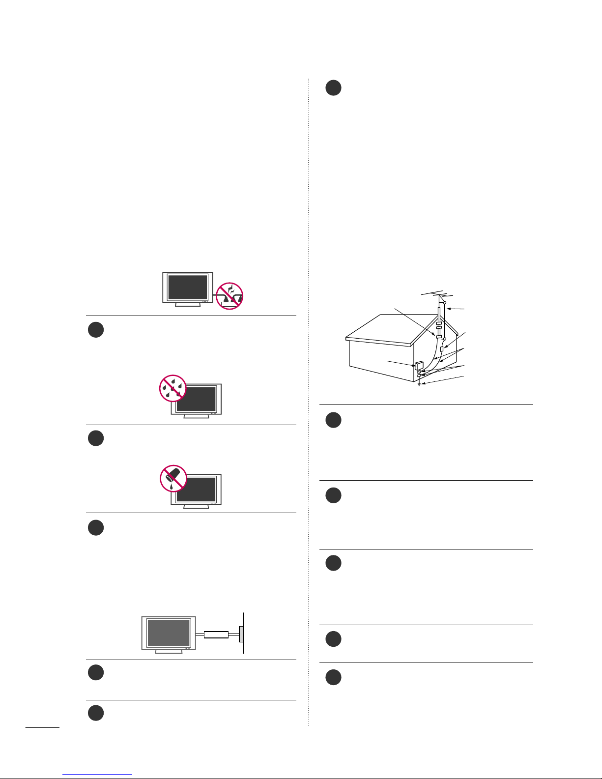
WARNING - To reduce the risk of fire or elec-
trical shock, do not expose this product to rain,
moisture or other liquids. Do not touch the TV
with wet hands. Do not install this product near
flammable objects such as gasoline or candles
or expose the TV to direct air conditioning.
Do not expose to dripping or splashing and do
not place objects filled with liquids, such as
vases, cups, etc. on or over the apparatus (e.g.
on shelves above the unit).
GGRROOUUNNDDIINNGG
Ensure that you connect the earth ground wire
to prevent possible electric shock (i.e. a TV
with a three-prong grounded AC plug must be
connected to a three-prong grounded AC out-
let). If grounding methods are not possible,
have a qualified electrician install a separate
circuit breaker.
Do not try to ground the unit by connecting it
to telephone wires, lightening rods, or gas pipes.
DDIISSCCOONNNNEECCTTIINNGG DDEEVVIICCEE RROOMM MMAAIINNSS
Mains plug is the disconnecting device. The
plug must remain readily operable.
Keep the product away from direct sunlight.
AANNTTEENNNNAASS
OOuuttddoooorr aanntteennnnaa ggrroouunnddiinngg
If an outdoor antenna is installed, follow the
precautions below. An outdoor antenna system
should not be located in the vicinity of over-
head power lines or other electric light or
power circuits, or where it can come in contact
with such power lines or circuits as death or
serious injury can occur.
Be sure the antenna system is grounded so as
to provide some protection against voltage
surges and built-up static charges.
Section 810 of the National Electrical Code
(NEC) in the U.S.A. provides information with
respect to proper grounding of the mast and
supporting structure, grounding of the lead-in
wire to an antenna discharge unit, size of
grounding conductors, location of antenna dis-
charge unit, connection to grounding electrodes
and requirements for the grounding electrode.
AAnntteennnnaa ggrroouunnddiinngg aaccccoorrddiinngg ttoo tthhee
NNaattiioonnaall EElleeccttrriiccaall CCooddee,, AANNSSII//NNPPAA 7700
CClleeaanniinngg
When cleaning, unplug the power cord and
scrub gently with a soft cloth to prevent
scratching. Do not spray water or other liquids
directly on the TV as electric shock may occur.
Do not clean with chemicals such as alcohol,
thinners or benzene.
MMoovviinngg
Make sure the product is turned off,
unplugged and all cables have been removed. It
may take 2 or more people to carry larger TVs.
Do not press against or put stress on the front
panel of the TV.
VVeennttiillaattiioonn
Install your TV where there is proper ventila-
tion. Do not install in a confined space such as
a bookcase. Do not cover the product with
cloth or other materials (e.g.) plastic while
plugged in. Do not install in excessively dusty
places.
If you smell smoke or other odors coming from
the TV or hear strange sounds, unplug the
power cord contact an authorized service center.
Do not press strongly upon the panel with
hand or sharp object such as nail, pencil or
pen, or make a scratch on it.
Power
Supply
Short-circuit
Bre ker
Antenna Lead in Wire
Antenna Discharge Unit
(NEC Section 810-20)
Grounding Conductor
(NEC Section 810-21)
Ground Clamps
Power Service Grounding
Electrode System (NEC
Art 250, Part H)
Ground Clamp
Electric Service
Equipment
NEC: National Electrical Code
15
20
21
22
23
24
25
16
17
18
19

5
CONTENTS
HOW TO USE THE OWNER'S MANUAL ON THE CD-ROM
To view the Owner's Manual on the CD-ROM, Adobe Acrobat Reader must be installed on your PC.
The “ACRORD" folder on the CD-ROM contains the installation programs for them.
If you want to install those programs, Open the “My Computer” Open the “LG” Open the
“ACRORD” double-click your language.
TO VIEW THE OWNER'S MANUAL ON THE CD-ROM
The Owner's Manual files are included in the supplied CD-ROM.
Load the supplied CD-ROM into the CD-ROM drive of your PC.
After a while, the web page of the CD-ROM will open automatically. (for Window only)
GGIf the web page does not appear automatically, open the Owner's Manual file directly.
Open the “My computer” Open the “LG” Open the “index.htm” file.
NOTE
!
FOR LCD TV
■
If the TV feels cold to the touch, there may be a small “flicker” when it is turned on. This is normal, there
is nothing wrong with TV.
■
Some minute dot defects may be visible on the screen, appearing as tiny red, green, or blue spots. However, they
have no adverse effect on the monitor's performance.
■
Avoid touching the LCD screen or holding your finger(s) against it for long periods of time. Doing so may
produce some temporary distortion effects on the screen.
On Dispos l (Only Hg l mp used LCD TV)
The fluorescent lamp used in this product contains a small amount of mercury. Do not dispose of this
product with general household waste. Disposal of this product must be carried out in accordance to the
regulations of your local authority.
When you select your roduct,
dis lay the PDF file. You can find the desired contents
easily using the bookmark.
WARNING / CAUTION
. . . . . . . . . . . . . . . . . . . . . . . . . . . . 2
SAFETY INSTRUCTIONS
. . . . . . . . . . . . . . . . . . . . . . . . . . 3
PREPARATION
Accessories . . . . . . . . . . . . . . . . . . . . . . . . . . . . . . . . . . . . . . . . . . . . . . . . . . . . . . 6
ront Panel Information . . . . . . . . . . . . . . . . . . . . . . . . . . . . . . . . . . . . . .7
Back Panel Information . . . . . . . . . . . . . . . . . . . . . . . . . . . . . . . . . . . . . . 8
Remote Control unctions . . . . . . . . . . . . . . . . . . . . . . . . . . . . . . . . . 9
Stand Instruction . . . . . . . . . . . . . . . . . . . . . . . . . . . . . . . . . . . . . . . . . . . . . 10
VESA Wall Mounting . . . . . . . . . . . . . . . . . . . . . . . . . . . . . . . . . . . . . . . . 11
Cable Management . . . . . . . . . . . . . . . . . . . . . . . . . . . . . . . . . . . . . . . . . 12
Desktop Pedestal Installation . . . . . . . . . . . . . . . . . . . . . . . . . . . . 13
Swivel Stand . . . . . . . . . . . . . . . . . . . . . . . . . . . . . . . . . . . . . . . . . . . . . . . . . . . . 13
Attaching the TV to a Desk . . . . . . . . . . . . . . . . . . . . . . . . . . . . . . 13
Securing the TV to the wall to prevent falling when
the tv is used on a stand . . . . . . . . . . . . . . . . . . . . . . . . . . . . . . . . 14
Antenna or Cable Connection . . . . . . . . . . . . . . . . . . . . . . . . . . 15
EXTERNAL EQUIPMENT SETUP
HD Receiver Setup . . . . . . . . . . . . . . . . . . . . . . . . . . . . . . . . . . . . . . . . . 16
DVD Setup . . . . . . . . . . . . . . . . . . . . . . . . . . . . . . . . . . . . . . . . . . . . . . . . . . . . . . 17
VCR Setup . . . . . . . . . . . . . . . . . . . . . . . . . . . . . . . . . . . . . . . . . . . . . . . . . . . . . 18
PC Setup . . . . . . . . . . . . . . . . . . . . . . . . . . . . . . . . . . . . . . . . . . . . . . . . . . . . . . . . 19
WATCHING TV
Turning On TV . . . . . . . . . . . . . . . . . . . . . . . . . . . . . . . . . . . . . . . . . . . . . . . . 20
Channel Setup . . . . . . . . . . . . . . . . . . . . . . . . . . . . . . . . . . . . . . . . . . . . . . . . 20
Initial Setting . . . . . . . . . . . . . . . . . . . . . . . . . . . . . . . . . . . . . . . . . . . . . . . . . . . 21
Quick Menu / avorite Channel Setup . . . . . . . . . . . . . . 22
On-Screen Menus Selection . . . . . . . . . . . . . . . . . . . . . . . . . . . . . 22
USB
Entry Modes . . . . . . . . . . . . . . . . . . . . . . . . . . . . . . . . . . . . . . . . . . . . . . . . . . . 26
Photo List . . . . . . . . . . . . . . . . . . . . . . . . . . . . . . . . . . . . . . . . . . . . . . . . . . . . . . . 27
Music List . . . . . . . . . . . . . . . . . . . . . . . . . . . . . . . . . . . . . . . . . . . . . . . . . . . . . . . 29
APPENDIX
Troubleshooting . . . . . . . . . . . . . . . . . . . . . . . . . . . . . . . . . . . . . . . . . . . . . . 31
Maintenance . . . . . . . . . . . . . . . . . . . . . . . . . . . . . . . . . . . . . . . . . . . . . . . . . . . 33
Product Specifications . . . . . . . . . . . . . . . . . . . . . . . . . . . . . . . . . . . . . 34

PREPARATION
6
PREPARATION
ACCESSORIES
Ensure that the following accessories are included with your TV. If an accessory is missing, lease contact the
dealer where you urchased the roduct.
The accessories included may differ from the images below.
For further information, see the the Owner's Manual files su lied CD-ROM.
OOppttiioonn EExxttrraass
* Wipe spots on the exterior only with
the polishing cloth.
* Do not wipe roughly when removing
stain. Excessive pressure may cause
scratch or discoloration.
Polishing Cloth
(This feature is not available
for all models.)
Copyright©2007 LGE,
AllRights Reserved.
D-sub 15 in Cable
1.5V 1.5V
Owner’s Manual Power Cord
Remote Control,
Batteries
INPUT
FAV
MUTE
TV
STB
POWER
Q.MENUMENU
AVMODE
RETURN
ENTER
VOLCH
123
456
78
0
9
FLASHBK
P
A
G
E
DVD
VCR
CD Manual
(Refer to P.5)
When using the VGA (D-sub 15 pin
cable) PC connection, the user
must use shielded signal interface
cables with ferrite cores to maintain
standards compliance.
Protection Cover
or
Protective Bracket and Bolt for
Power Cord
(This feature is not available for all models.)
(Refer to P.12)
OOnnllyy 3377//4422LLGG55**
Bolts for stand assembly
(Refer to P.10)
Screw for stand fixing
(Refer to P.13)
x 4 x 4

PREPARATION
7
FRONT PANEL INFORMATION
■
Image shown may differ from your TV.
■
NOTE: If your TV has a protection tape attached, remove the tape.
And then wipe the TV with a cloth (If a polishing cloth is included with your TV, use it).
POWER Button
Power/Standby Indicator
Illuminates red in standby mode.
Illuminates blue when the set is switched on.
(Can be adjusted using PPoowweerr IInnddiiccaattoorrin
the OPTION menu.)
CH
VOL
MENU
INPUT
ENTER
CHANNEL ( , )
Buttons
VOLUME (+, -)
Buttons
ENTER Button
MENU Button
INPUT Button
Intelligent Sensor
Adjusts picture according to the
surrounding conditions
Remote Control Sensor

PREPARATION
8
BACK PANEL INFORMATION
PREPARATION
■
Image shown may differ from your TV.
AV IN 2
L/MONO
R
AUDIO
VIDEO
HDMI IN 3 USB IN
( )
RGB IN
COMPONENT IN
AUDIO
(RGB/DVI)
RGB(PC)
REMOTE
CONTROL IN
ANTENNA/
CABLE IN
1
2
RS-232C IN
(CONTROL & SERVICE)
VIDEO
AUDIO
OPTICAL COAXIAL
DIGITAL AUDIO OUT
AUDIO OUT
AV IN 1
R
HDMI/DVI IN
2
1
VIDEO
MONO
()
AUDIO
S-VIDEO
1
3
4
6
7
8
2
9
9
510
1
R
( )
11
HDMI/DVI IN, HDMI IN
Digital Connection.
Supports HD video and Digital audio. Doesn’t
support 480i.
Accepts DVI video using an adapter or HDMI to
DVI cable (not included).
COMPONENT IN
Analog Connection.
Supports HD.
Uses a red, green, and blue cable for video & red
and white for audio.
RGB (PC)
Analog PC Connection. Uses a D-sub 15 pin cable
(VGA cable).
AUDIO (RGB/DVI)
1/8” headphone jack for analog PC audio input.
REMOTE CONTROL IN PORT
or a wired remote control.
RS-232C IN (CONTROL & SERVICE) PORT
Used by third party devices.
ANTENNA/CABLE IN
Connect over-the air signals to this jack.
Connect cable signals to this jack.
DIGITAL AUDIO OUT
Digital audio output for use with amps and home
theater systems.
Includes an optical and coaxial connection.
Note: In standby mode, these ports do not work.
AUDIO OUT
Analog audio output for use with amps and home
theater systems.
AV (Audio/Video) IN
Analog composite connection. Supports standard
definition video only (480i).
S-VIDEO
Better quality than standard composition.
Supports standard definition video only (480i).
USB INPUT
Used for viewing photos and listening to MP3s.
Power Cord Socket
or operation with AC power.
Caution: Never attempt to operate the TV on DC
power.
1
2
3
4
5
6
9
10
11
7
8
(Except
42/47/52LG50DC)

PREPARATION
9
REMOTE CONTROL FUNCTIONS
When using the remote control, aim it at the remote control sensor on the TV.
INPUT
FAV
MUTE
TV
STB
POWER
Q. MENU MENU
AV MODERETURN
ENTER
VOL CH
123
456
78
0
9
FLASHBK
P
A
G
E
DVD
VCR
Inst lling B tteries
■
Open the battery compartment cover on the back side and install the batteries
matching correct polarity (+with +,-with -).
■
Install two 1.5V AAA batteries. Don’t mix old or used batteries with new ones.
■
Close cover.
TV/STB/DVD/VCR
POWER
Q.MENU
MENU
INPUT
THUMBSTICK
(U /Down/Left
Right/ENTER)
RETURN
SIMPLINK
AV MODE
VOLUME UP
/DOWN
FAV
MUTE
CHANNEL
UP/DOWN
PAGE
UP/DOWN
— (DASH)
FLASHBK
Select the remote operating mode: TV, STB, DVD, or VCR.
Turns your TV or any other programmed equipment on or
off, depending on the mode.
Select the desired quick menu source.
Displays the main menu.
Clear all on-screen displays and return to TV viewing from
any menu.
External input modes rotate in regular sequence.
Navigate the on-screen menus and adjust the system set-
tings to your preference.
Allows the user to move return one step in an interactive
application or other user interaction function.
See a list of AV devices connected to TV.
When you toggle this button, the SIMPLINK menu appears
at the screen.
It helps you select and set images and sounds.
Increase/decrease the sound level.
Scroll through the programmed avorite channels.
Switch the sound on or off.
Select available channels.
Move from one full set of screen information to the next one.
Used to enter a program number for multiple program
channels such as 2-1, 2-2, etc.
Tune to the last channel viewed.
Control video cassette recorders or DVD players.
Control USB menu (Photo List and Music List.)
Control the SIMPLINK compatible devices.
NUMBER button
VCR/DVD, USB,
SIMPLINK
Control buttons

PREPARATION
10
STAND INSTRUCTION
PREPARATION
■
Image shown may differ from your TV.
Assemble the parts of the SSTTAANNDD BBOODDYY
with CCOOVVEERR BBAASSEEof the TV.
2
Assemble the TV as shown.
3
ix the 4 bolts securely using the holes in the
back of the TV.
4
SSTTAANNDD BBOODDYY
CCOOVVEERR BBAASSEE
Carefully place the TV screen side down on a cush-
ioned surface to protect the screen from damage.
1
INSTALLATION (
Only 37/42LG5*)
DETACHMENT
Carefully place the TV screen side down on a
cushioned surface to protect the screen from
damage.
1
Loose the bolts from TV.
2
Detach the stand from TV.
3
After removing the stand, install the included
pprrootteeccttiioonn ccoovveerrover the hole for the stand.
Press the PPRROOTTEECCTTIIOONN CCOOVVEERRinto the TV
until you hear it click.
PROTECTION COVER
GGWhen assembling the desk type stand, make sure
the bolt is fully tightened. (If not tightened fully,
the TV can tilt forward after the product installa-
tion). Do not over tighten.
NOTE
!

PREPARATION
11
VESA WALL MOUNTING
Install your wall mount on a solid wall perpendicular to the floor. When attaching to other building materials, please
contact your nearest dealer.
If installed on a ceiling or slanted wall, it may fall and result in severe personal injury.
We recommend that you use an LG brand wall mount when mounting the TV to a wall.
LG recommends that wall mounting be performed by a qualified professional installer.
AA
BB
GGDo not install your wall mount kit while your TV is turned on. It may result in personal injury due to electric
shock.
CAUTION
GGScrew length needed depends on the wall mount
used. or further information, refer to the instruc-
tions included with the mount.
GGStandard dimensions for wall mount kits are shown
in the table.
GGWhen purchasing our wall mount kit, a detailed
installation manual and all parts necessary for
assembly are provided.
GGDo not use screws longer then the standard dimen-
sion, as they may cause damage to the inside to
the TV.
GGor wall mounts that do not comply with the VESA
standard screw specifications, the length of the
screws may differ depending on their specifica-
tions.
GGDo not use screws that do not comply with the
VESA standard screw specifications.
Do not use fasten the screws too strongly, this may
damage the TV or cause the TV to a fall, leading to
personal injury. LG is not liable for these kinds of
accidents.
GGLG is not liable for TV damage or personal injury
when a non-VESA or non specified wall mount is
used or the consumer fails to follow the TV installa-
tion instructions.
NOTE
!
Product Model VESA
(A *B) Standard Screw Quantity
37LG5*
42LG5*
47LG5*
52LG5*
200 * 200
800 * 400
M6
M6
4
4
LCD TV

PREPARATION
12
PREPARATIONPREPARATION
CABLE MANAGEMENT
Connect the cables as necessary.
To connect additional equipment, see the
EXTERNAL EQUIPMENT SETUP section.
Secure the power cable with the PROTECTIVE
BRACKET and the screw as shown. It will help
prevent the power cable from being removed
by accident.
Install the CABLE MANAGEMENT CLIP as
shown.
CABLE MANAGEMENT CLIP
PROTECTIVE BRACKET
(This feature is not available for all models.)
Put the cables inside the CABLE MANAGEMENT
CLIP and snap it closed.
1
2
3
■
Here shown may be somewhat different from your TV.

PREPARATION
13
DESKTOP PEDESTAL INSTALLATION
or proper ventilation, allow a clearance of 4 inches on all four sides from the wall.
■
Image shown may differ from your TV.
4 inches
4 inches
4 inches 4 inches
SWIVEL STAND
After installing the TV, you can adjust the TV set manually to the left or right direction by 20 degrees to suit
your viewing position.
GGEnsure adequate ventilation by following the clearance recommendations.
GGDo not mount near or above any type of heat source.
CAUTION
ATTACHING THE TV TO A DESK (Only 37/42LG5*)
The TV must be attached to a desk so it cannot be pulled in a forward/backward direction, potentially causing
injury or damaging the product.
GGTo prevent TV from falling over, the TV should be securely attached to the floor/wall per installation
instructions. Tipping, shaking, or rocking the machine may cause injury.
WARNING
1-Screw
(provided as parts of the product)
Desk
Stand

We recommend that you set up the TV close to a wall so it cannot fall over if pushed backwards.
Additionally, we recommend that the TV be attached to a wall so it cannot be pulled in a forward direction,
potentially causing injury or damaging the product.
Caution: Please make sure that children don’t climb on or hang from the TV.
■Insert the eye-bolts (or TV brackets and bolts) to tighten the product to the wall as shown in the picture.
*If your product has the bolts in the eye-bolts position before inserting the eye-bolts, loosen the bolts.
* Insert the eye-bolts or TV brackets/bolts and tighten them securely in the upper holes.
Secure the wall brackets with the bolts (sold separately) to the wall. Match the height of the bracket that is
mounted on the wall to the holes in the product.
Ensure the eye-bolts or brackets are tightened securely.
■Use a sturdy rope (sold separately) to tie the product. It is safer to tie
the rope so it becomes horizontal between the wall and the product.
■
You should purchase necessary components to prevent TV from falling off of the stand.
■
Image shown may differ from your TV.
GGUse a platform or cabinet strong enough and large enough to support the size and weight of the TV.
GGTo use the TV safely make sure that the height of the bracket on the wall and the one on the TV are the same.
NOTE
!
PREPARATION
14
SECURING THE TV TO THE WALL TO PREVENT FALLING
WHEN THE TV IS USED ON A STAND
PREPARATION

PREPARATION
15
ANTENNA OR CABLE CONNECTION
1. Antenn (An log or Digit l)
Wall Antenna Socket or Outdoor Antenna without a Cable Box
Connection.
or optimum picture quality, adjust antenna direction if needed.
2. C ble
W ll
Antenn
Socket
Outdoor
Antenn
(VHF, UHF)
C ble TV
W ll J ck
Multi-f mily Dwellings/Ap rtments
(Connect to w ll ntenn socket)
RF Co xi l Wire (75 ohm)
Single-f mily Dwellings /Houses
(Connect to w ll j ck for outdoor ntenn )
Be c reful not to bend the copper wire
when connecting the ntenn .
Copper Wire
■To improve the picture quality in a poor signal area, please purchase a signal amplifier and install properly.
■If the antenna needs to be split for two TV’s, install a 2-Way Signal Splitter.
■If the antenna is not installed properly, contact your dealer for assistance.
ANTENNA/
CABLE IN
R
( )
ANTENNA/
CABLE IN
R
( )
■To prevent damage do not connect to the power outlet until all connections are made between the devices.

EXTERNAL EQUIPMENT SETUP
16
EXTERNAL EQUIPMENT SETUP
HD RECEIVER SETUP
This TV can receive Digital Over-the-air/Cable signals without an external digital set-to box. However, if you do
receive digital signals from a digital set-to box or other digital external device, refer to the figure as shown below.
Component Connection
1. How to connect
Connect the video outputs (Y, PB, PR)of the digital set-
top box to the CCOOMMPPOONNEENNTT IINN VVIIDDEEOO 11jacks on
the TV. Match the jack colors (Y = green, PB= blue, and
PR= red).
Connect the audio output of the digital set-top box to
the CCOOMMPPOONNEENNTT IINN AAUUDDIIOO 11jacks on the TV.
2. How to use
■Turn on the digital set-top box.
(Refer to the owner’s manual for the digital set-top box. operation)
■Select the CCoommppoonneenntt11 input source on the TV using
the IINNPPUUTT button on the remote control.
■If connected to CCOOMMPPOONNEENNTT IINN22 input, select the
CCoommppoonneenntt 22 input source on the TV.
■To prevent the equipment damage, never plug in any power cords until you have finished connecting all equipment.
■
Image shown may differ from your TV.
2
1
RGB IN
AUDIO
(RGB/DVI)
RGB(PC)
REMOT
CONTROL
(
COMPONENT IN
1
2
VIDEO
LYP
BPRR
AUDIO
Y L RPBPR
12
Y, CB/PB, CR/PR
Su orted Resolutions
Horizontal Vertical
requency(KHz)requency(Hz)
15.73 59.94
15.73 60.00
31.47 59.94
31.50 60.00
44.96 59.94
45.00 60.00
33.72 59.94
33.75 60.00
26.97 23.976
27.00 24.00
33.71 29.97
33.75 30.00
67.432 59.94
67.50 60.00
Resolution
720x480i
720x480p
1280x720p
1920x1080i
1920x1080p
Signal
480i
480p
720p
108 0 i
108 0 p
Component
Yes
Yes
Yes
Yes
Yes
HDMI
No
Yes
Yes
Yes
Yes

EXTERNAL EQUIPMENT SETUP
17
DVD SETUP
HDMI Connection
Connect the HDMI output of the DVD to the
HHDDMMII//DDVVII IINN11, 22, or 33* jack on the TV.
No separate audio connection is necessary.
HDMI supports both audio and video.
1. How to connect
2. How to use
■Select the HHDDMMII11, HHDDMMII22, or HHDDMMII33* input source on
the TV using the IINNPPUUTTbutton on the remote control.
■Refer to the DVD player's manual for operating instructions.
* HDMI 3: Except 42/47/52LG50DC
2
1
Component Connection
Connect the video outputs (Y, PB, PR)of the DVD to the
CCOOMMPPOONNEENNTT IINN VVIIDDEEOO11jacks on the TV.
Match the jack colors (Y = green, PB= blue, and PR= red).
Connect the audio outputs of the DVD to the
CCOOMMPPOONNEENNTT IINN AAUUDDIIOO11jacks on the TV.
1. How to connect
2. How to use
■Turn on the DVD player, insert a DVD.
■Select the CCoommppoonneenntt11input source on the TV using
the IINNPPUUTTbutton on the remote control.
■If connected to CCOOMMPPOONNEENNTT IINN 22 input, select the
CCoommppoonneenntt 22 input source on the TV.
■Refer to the DVD player's manual for operating instructions.
2
1
RGB IN
AUDIO
(RGB/DVI)
RGB(PC)
REMOT
CONTRO
COMPONENT IN
1
2
VIDEO
LYP
BPRR
AUDIO
Y L RPBPR
1 2
COMPONENT IN
AUDIO
(RGB/D
RGB(PC)
1
2
VIDEO
LYP
BPR
A
HDMI/DVI IN
2
1
HDMI-DVD OUTPUT
1

EXTERNAL EQUIPMENT SETUP
18
EXTERNAL EQUIPMENT SETUP
VCR SETUP
Composite (RCA) Connection
GGIf you have a mono VCR, connect the audio cable from
the VCR to the AAUUDDIIOO LL//MMOONNOOjack of the TV.
NOTE
!
NT IN
AUDIO
(RGB/DVI)
REMOTE
CONTROL IN
ANTENNA/
CABLE IN
RS-232C IN
(CONTROL & SERVICE)
L R
AUDIO
OPTICAL COAXIAL
DIGITAL AUDIO OUT
AV IN 1
VIDEO L R
(MONO)
AUDIO
S-VIDEO
AUDIO OUT
L R
S-VIDEO VIDEO
OUTPUT
SWITCH
ANT IN
ANT OUT
1
Connect the AAUUDDIIOO/VVIIDDEEOOjacks between TV and
VCR. Match the jack colors (Video = yellow, Audio Left
= white, and Audio Right = red)
1. How to connect
2. How to use
■Insert a video tape into the VCR and press PLAY on the VCR.
(Refer to the VCR owner’s manual.)
■Select the AAVV11input source on the TV using the IINNPPUUTT
button on the remote control.
■If connected to AAVV IINN22, select AAVV22 input source on the TV.
GGDo not connect to both Video and S-Video at the same
time. In the event that you connect both Video and the
S-Video cables, only the S-Video will work.
CAUTION
GGS-Video provides better quality than composite. Use it
when available.
NOTE
!
S-Video Connection
NT IN
AUDIO
(RGB/DVI)
REMOTE
CONTROL IN
ANTENNA/
CABLE IN
RS-232C IN
(CONTROL & SERVICE)
L R
AUDIO
OPTICAL COAXIAL
DIGITAL AUDIO OUT
AV IN 1
VIDEO LR
(MONO)
AUDIO
S-VIDEO
AUDIO OUT
L R
S-VIDEO VIDEO
OUTPUT
SWITCH
ANT IN
ANT OUT
12
Connect the S-VIDEO output of the VCR to the
SS--VVIIDDEEOO input on the TV.
Connect the audio outputs of the VCR to the AAUUDDIIOO
input jacks on the TV.
1. How to connect
2. How to use
■Insert a video tape into the VCR and press PLAY on the VCR.
(Refer to the VCR owner’s manual.)
■Select the AAVV11input source on the TV using the IINNPPUUTT
button on the remote control.
1
1
2

EXTERNAL EQUIPMENT SETUP
19
PC SETUP
Connect the VGA output of the PC to the RRGGBB ((PPCC))
jack on the TV.
Connect the PC audio output to the AAUUDDIIOO
((RRGGBB//DDVVII))jack on the TV.
1. How to connect
2. How to use
■Turn on the PC and the TV.
■Select the RRGGBB--PPCCinput source on the TV using the
IINNPPUUTTbutton on the remote control.
2
1
VGA (D-Sub 15 pin) Connection
COMPONENT IN
REMOTE
CONTROL IN
1
2
(CO
VIDEO
LYP
BPRR
AUDIO
I IN
RGB IN
AUDIO
(RGB/DVI)
RGB(PC)
RGB OUTPUT AUDIO
1 2
Supported Displ y Specific tions (RGB-PC, HDMI-PC)
Resolution
720x400
640x350
640x480
1920x1080
HDMI-PC
Horizontal Vertical
requency(KHz)requency(Hz)
31.468 70.09
31.469 70.08
31.469 59.94
35.156 56.25
37.879 60.31
48.363 60.00
56.476 70.06
47.776 59.87
63.981 60.02
47.712 60.015
75.00 60.00
66.587 59.934
67.5 60.00
800x600
1024x768
1280x768
1280x1024
1360x768
1600x1200
1920x1080
RGB-PC

WATCHING TV
20
WATCHING TV
TURNING ON TV
CHANNEL SETUP
NOTE
!
GGIf you intend to be away on vacation, disconnect the power plug from the wall power outlet.
irst, connect power cord correctly.
At this moment, the TV switches to standby mode.
■In standby mode to turn TV on, press the , IINNPPUUTT,(())button on the TV or press the PPOOWWEERR,
IINNPPUUTT, CCHH((or )), NNuummbbeerr ((00~99))button on the remote control.
Select the viewing source by using the IINNPPUUTTbutton on the remote control.
■This TV is programmed to remember which power state it was last set to, even if the power cord is out.
When finished using the TV, press the PPOOWWEERRbutton on the remote control. The TV reverts to standby mode.
1
2
3
Auto Scan (Auto Tuning)
Automatically finds all channels available through antenna or cable in uts, and stores them in memory on the
channel list.
Run Auto Tuning again after any Antenna/Cable connection changes.
Select CCHHAANNNNEELL.
Select AAuuttoo TTuunniinngg.
Select YYeess.
Run AAuuttoo ttuunniinngg.
1
MENU
3
2
ENTER
ENTER
4
ENTER
■A password is required to gain access to
Auto Tuning menu if the Lock System is
turned on.
5
RETURN
Return to the previous menu.
MENU
Return to TV viewing.
Enter
Move
CHANNEL
Enter
Move
CHANNEL
Auto Tuning
Manual Tuning
Channel Edit
Auto Tuning
Manual Tuning
Channel Edit
Press ‘Yes’ button to begin
auto tuning.
Yes
No
Other manuals for 37LG50 Series
2
This manual suits for next models
8
Table of contents
Other LG LCD TV manuals