LG 47LG6000 User manual

OWNER’S MANUAL
LCD TV MODELS
3322LLGG6600****
3377LLGG6600****
4422LLGG6600****
4422LLGG6611****
4477LLGG6600****
PLASMA TV MODELS
3322PPGG6600****
4422PPGG6600****
5500PPGG6600****
5500PPGG7700****
6600PPGG7700****
5500PPGG4400****
LCD TV PLASMA TV
Please read this manual carefully before operatin
your TV.
Retain it for future reference.
Record model number and serial number of the TV.
Refer to the label on the back cover and quote this
information.
To your dealer when requirin service.
ENGLISH
Trade Mark of the DVB Di ital Video
Broadcastin Project (1991 to 1996)
IIDD NNuummbbeerr((ss))::5102: 32LG6000-ZA
5103: 37LG6000-ZA
5104: 42LG6000-ZA
5484: 42LG6100-ZB
5105: 47LG6000-ZA
5571: 42LG6000-ZG
5572: 47LG6000-ZG
5719: 42LG6100-ZH
5251: 32PG6000-ZA
5252: 32PG6010-ZE
5100: 42PG6000-ZA
5249: 42PG6010-ZE
5101: 50PG6000-ZA
5250: 50PG6010-ZE
5245: 50PG7000-ZB
5244: 60PG7000-ZB
5246: 50PG4000-ZA
This product qualifies for ENERGY STAR in
the “factory default (Home mode)” settin
and this is the settin in which power savin s
will be achieved.(Plasma TV only)


1
ACCESSORIES
ACCESSORIES
Ensure that the following accessories are included with your TV. If an accessory is missing, please contact the
dealer where you purchased the TV.
■
Image shown may differ from your TV
Owner’s Manual Batteries
Remote Control
Power Cord
Polishing Cloth
Polishing cloth for use on
the screen.
his feature is not available for all models.
* Lightly wipe any stains or fingerprints on
the surface of the V with the polishing
cloth.
Do not use excessive force. his may cause
scratching or discolouration.
LLCCDD TTVV mmooddeellss
Cable management clip
bolts for stand assembly
(Refer to p. 8)
Protection cover
(Refer to p.13)
32LG 60** : 3E
37LG60** : 4E
2E
4E
1E
4E
(32/37LG60** only) (42LG60**, 42LG61** only)
Cable management clip
Protection cover
(Refer to p.13)
Ferrite core
(Refer to p.11)
( his feature is not available for
all models.)
PPLLSSMM TTVV mmooddeellss
(50PG60** ,
50/60PG70** only)
(50PG40** only)
(Except 50PG40** )
Cable Holder
(32/42PG60** :1EA,
50PG40** :2EA)
* his feature is not available for all models.
bolts for stand assembly
(Refer to p. 8)
4E
(32PG60** only)

CONTENTS
2
CONTENTS
ACCESSORIES
. . . . . . . . . . . . . . . . . . . . . . . . . . . . . . . . . . . . . . . . . . . .
1
PREPARA ION
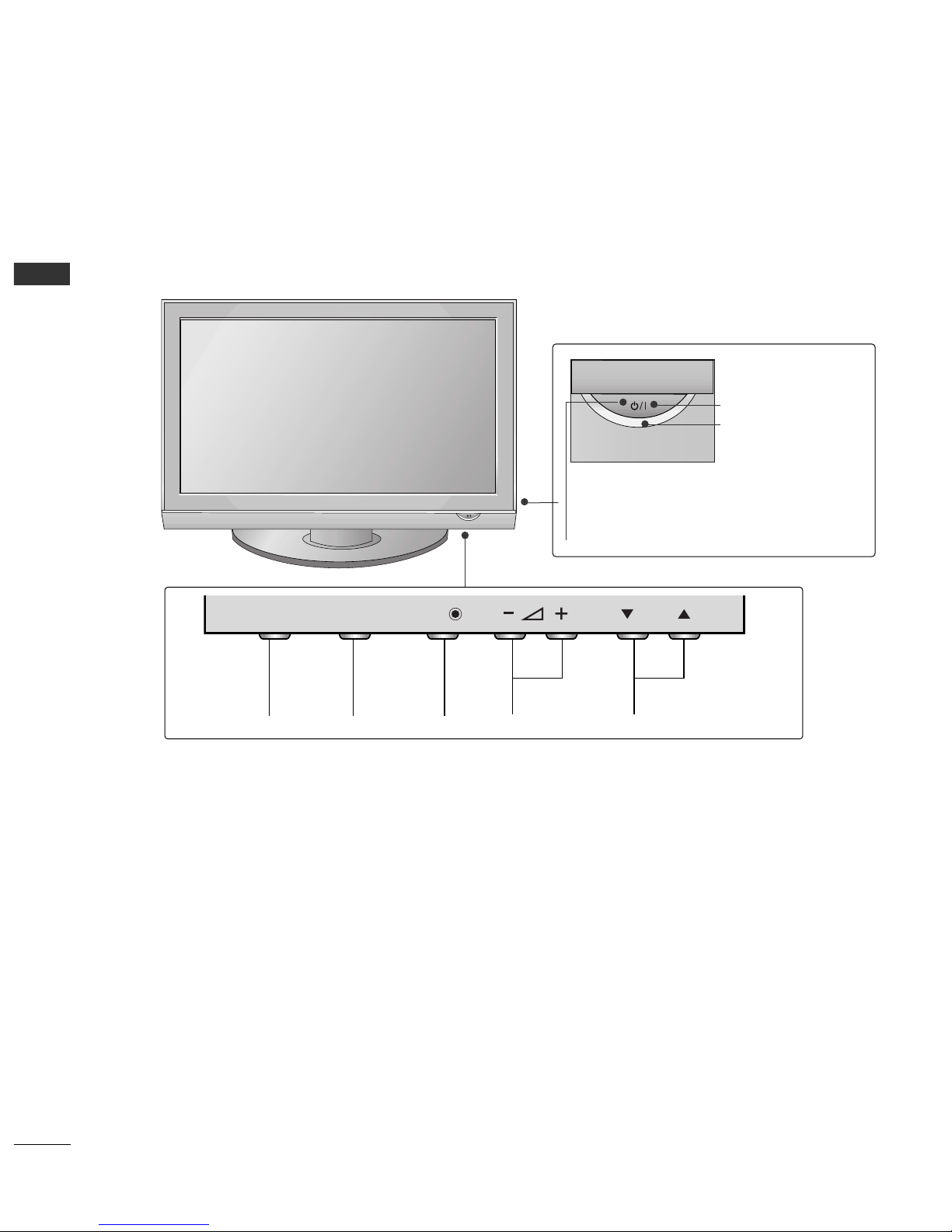
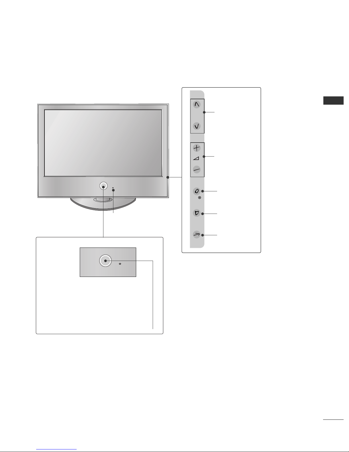
Front Panel Controls..................................................... 4
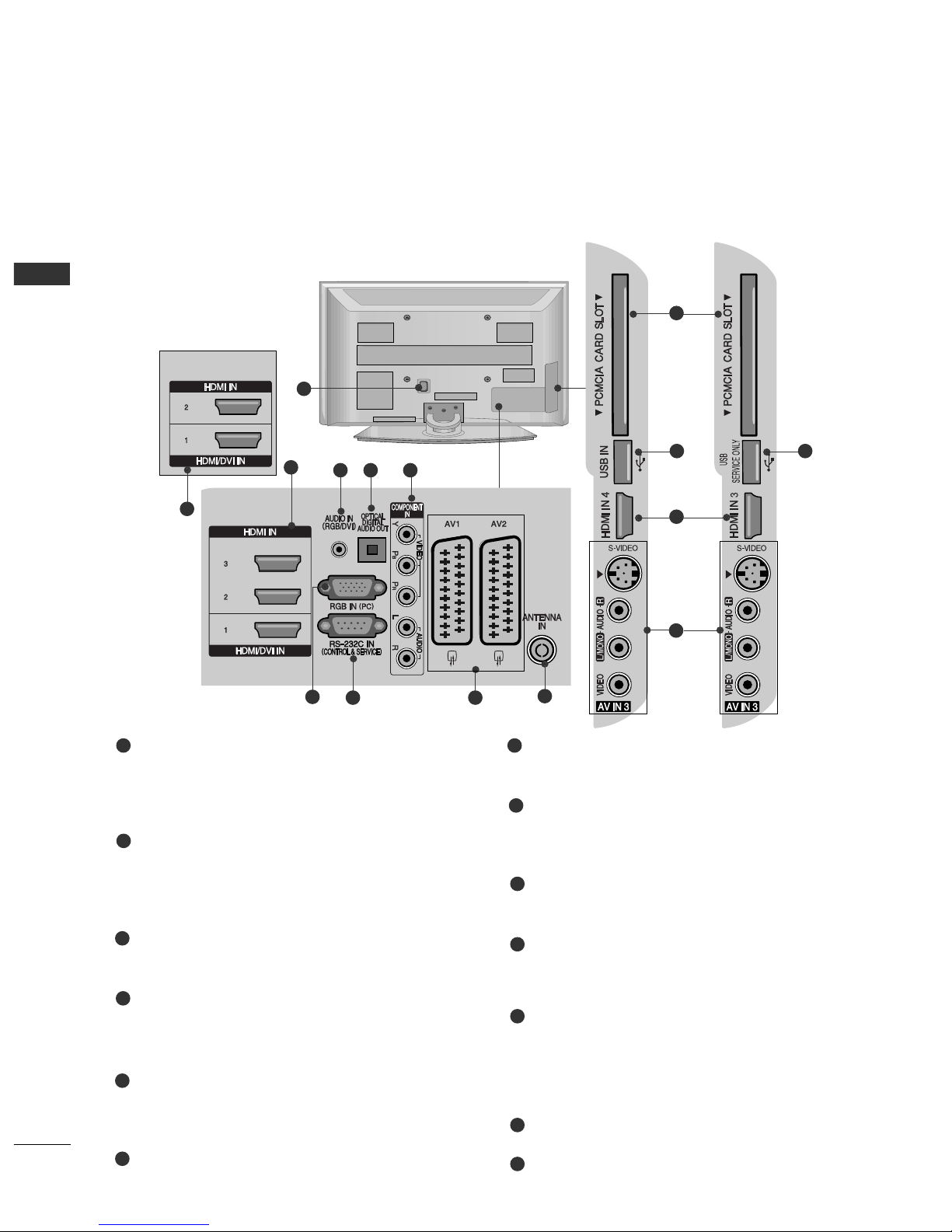
Back Panel Information ................................................ 6
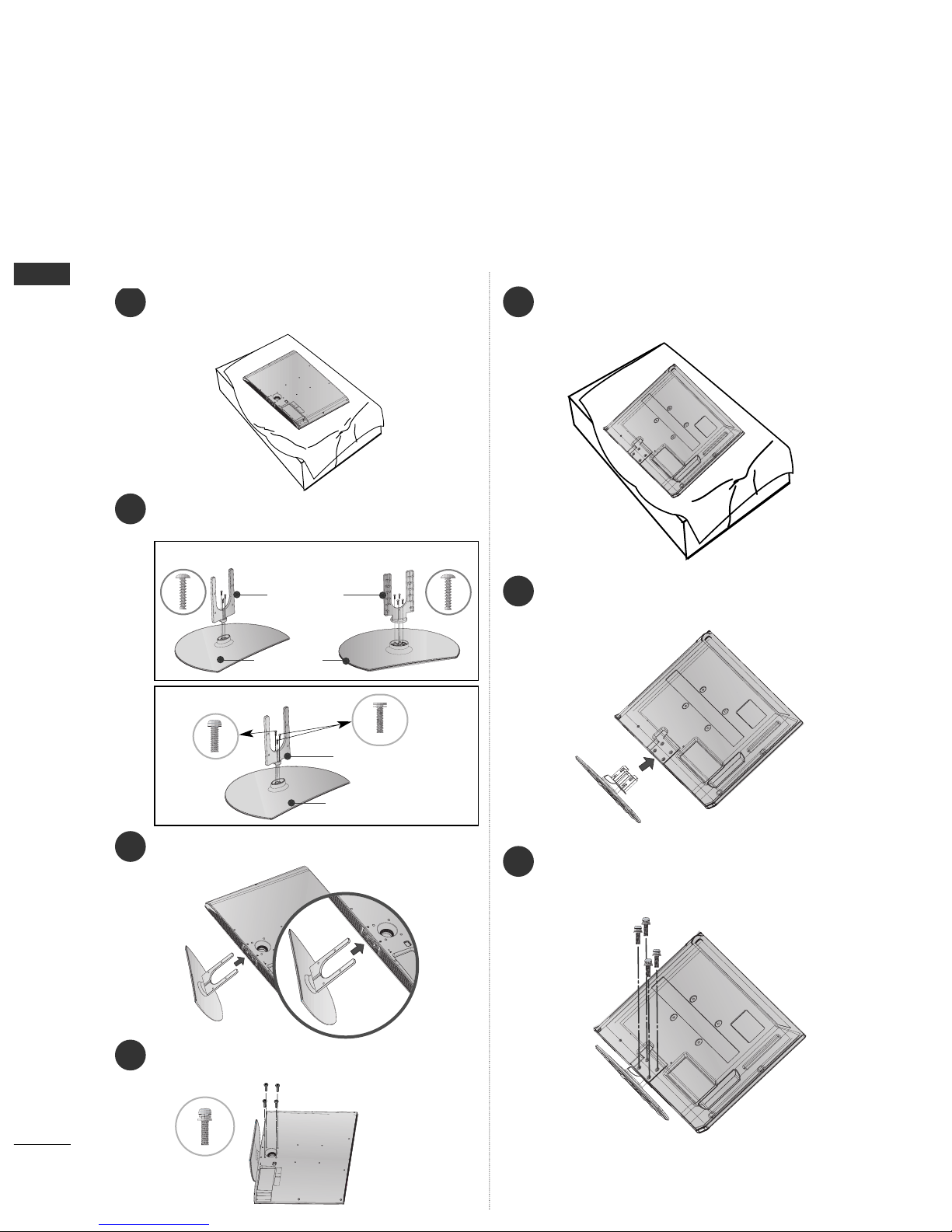
Stand Installation........................................................... 8
Please set it up carefully so the product doesn’t fall
over..................................................................................... 9
Back Cover for Wire Arran ement .......................... 10
Swivel Stand ................................................................. 11
Desktop Pedestal Installation ................................... 12
Wall Mount: Horizontal Installation........................ 13
Antenna Connection................................................... 14
EX ERNAL EQUIPMEN SE UP
HD Receiver Setup ...................................................... 15
DVD Setup..................................................................... 17
VCR Setup..................................................................... 20
Insertion of CI Module .............................................. 22
Di ital Audio Out Setup............................................ 23
Other A/V Source Setup........................................... 24
Usb in Setup................................................................. 25
PC Setup........................................................................ 26
- Screen Setup for PC Mode .............................. 29
WA CHING V / PROGRAMME CON ROL
Remote Control Key Functions ............................... 34
Turnin on the TV....................................................... 36
Pro ramme Selection ................................................ 36
Volume Adjustment ................................................... 36
Quick Menu ................................................................. 37
On-Screen Menus Selection and Adjustment..... 38
Auto Pro ramme Tunin ............................................ 39
Manual Pro ramme Tunin (In Di ital Mode)..... 40
Manual Pro ramme Tunin (In Analo ue Mode) ... 41
Pro ramme Edit ........................................................... 43
Booster........................................................................... 46
Software Update.......................................................... 47
Dia nostics ................................................................... 48
CI Information.............................................................. 49
Selectin the Pro ramme Table............................... 50
Input List........................................................................ 51
................................................................. 52
Input Label .................................................................... 54
AV Mode........................................................................ 55
O USE HE USB DEVICE
When connectin the USB device.......................... 56
Photo List ...................................................................... 57
Music List........................................................................61
EPG (ELEC RONIC PROGRAMME
GUIDE) (IN DIGI AL MODE)
- Switch on/off EPG ............................................... 64
- Select Pro ramme ................................................ 64
- Button Function in NOW/NEXT Guide Mode 65
- Button Function in 8 Day Guide Mode.......... 65
- Button Function in Date Chan e Mode......... 65
-
Button Function in Extended Description Box .
66
-
Button Function in Record/Remind Settin Mode
.66
- Button Function in Schedule List Mode......... 66
PIC URE CON ROL
Picture Size (Aspect Ratio) Control....................... 67
Preset Picture Settin s
- Picture Mode-Preset............................................ 69
- Auto Colour Tone Control
(Warm/Medium/Cool) ........................................ 70
Manual Picture Adjustment
- Picture Mode-User option................................. 71
-Picture Mode-Expert Control............................. 72
Picture Improvement Technolo y........................... 73
Advanced - Film Mode/ Real Cinema .................... 74
Advanced - Black(Darkness) Level ......................... 75
Advanced - Trumotion.................................................76
TruMotion Demo ..........................................................77
Eye Care..........................................................................78
Picture Reset................................................................. 79

CONTENTS
3
Power Indicator .............................................................80
Ima e Stickin Minimization (ISM) Method ........ 81
Power Savin Picture Mode...................................... 82
SOUND & LANGUAGE CON ROL
Auto Volume Leveler................................................... 83
Preset Sound Settin s - Sound Mode................... 84
Sound Settin Adjustment -User Mode ............... 85
SRS TruSurround XT .................................................. 85
Clear Voice.................................................................... 86
Balance........................................................................... 87
TV Speakers On/ Off Setup..................................... 88
Selectin Di ital Audio Out ..................................... 89
Audio Reset .................................................................. 90
I/II
- Stereo/Dual Reception (In Analo ue Mode
Only)........................................................................... 91
- NICAM Reception (In Analo ue Mode Only)... 92
- Speaker Sound Output Selection.................... 92
On-Screen Menu Lan ua e/Country Selection.. 93
Lan ua e Selection (In Di ital Mode only)......... 94
IME SE ING
Clock Setup .................................................................. 95
Auto On/ Off Timer Settin ..................................... 96
Auto Shut-off Settin ................................................. 97
Time Zone Setup ........................................................ 98
Sleep Timer Settin .................................................... 98
PAREN AL CON ROL / RA INGS
Set Password & Lock System................................... 99
Block Pro ramme ...................................................... 100
Parental Control......................................................... 101
Key Lock ...................................................................... 102
ELE EX
Switch on/off ............................................................. 103
SIMPLE Text................................................................ 103
TOP Text...................................................................... 103
FASTEXT...................................................................... 104
Special Teletext Functions ...................................... 104
DIGI AL ELE EX
Teletext within Di ital Service................................ 105
Teletext in Di ital Service........................................ 105
APPENDIX
Troubleshootin ........................................................ 106
Maintenance .............................................................. 108
Product Specifications............................................. 109
Pro rammin the Remote Control......................... 111
IR Codes....................................................................... 113
External Control Device Setup............................... 115

PREPARATION
4
PREPARATION
FRONT PANEL CONTROLS
■
Ima e shown may differ from your TV
■
If your TV has a protection film attached, remove the film and then wipe the product with a polishin cloth.
Plasma V Models
PR
VOL
OK
MENU
INPUT
PR
VOL
OK
MENU
INPUT
Remote Control Sensor
POWER
Power/Standby Indicator
• Illuminates red in standby mode.
• Illuminates reen when the TV is
switched on.
PROGRAMMEVOLUMEMENU OKINPUT
P
OKOK
MENUMENU
INPUTINPUT

P
5
PREPARATION
LCD V Models
P
OK
MENU
INPUT
P
PROGRAMME
VOLUME
OK
MENU
INPUT
Intelligent Sensor
Adjusts picture according to the sur-
rounding conditions
POWER
Remote Control Sensor
Power/Standby Indicator
• Illuminates red in standby mode
• Illuminates White when the TV is switched on
Note: You can adjust PPoowweerr IInnddiiccaattoorrin the
OPTION menu

PREPARATION
6
PREPARATION
BACK PANEL INFORMATION
A
Ima e shown may differ from your TV.
Power Cord Socket
This TV operates on an AC power. The volta e is
indicated on the Specifications pa e. Never
attempt to operate the TV on DC power.
HDMI Input
Connect a HDMI si nal to HDMI IN.
Or DVI(VIDEO)si nal to HDMI/DVI port with DVI
to HDMI cable.
RGB/DVI Audio Input
Connect the audio from a PC or DTV.
OPTICAL DIGITAL AUDIO OUT
Connect di ital audio from various types of equipment.
Note: In standby mode, these ports do not work.
Component Input
Connect a component video/audio device to
these jacks.
RGB Input
Connect the output from a PC.
RS-232C IN (CONTROL & SERVICE) PORT
Connect to the RS-232C port on a PC.
Euro Scart Socket (AV1/AV2)
Connect scart socket input or output from an
external device to these jacks.
Antenna Input
Connect RF antenna to this jack.
PCMCIA (Personal Computer Memory Card
International Association) Card Slot
(This feature is not available in all countries.)
S-Video Input
Connect S-Video out from an S-VIDEO device.
Audio/Video Input
Connect audio/video output from an external
device to these jacks.
USB Input
SERVICE ONLY PORT
1
2
3
4
7
8
9
10
11
12
13
1
5
6
23 4 5
67 8 9
Plasma V Models
50PG40** Only
50PG40** Only
10
12 13
2
11
2

7
PREPARATION
LCD V Models
Power Cord Socket
This TV operates on an AC power. The volta e is
indicated on the Specifications pa e. Never
attempt to operate the TV on DC power.
RS-232C IN (CONTROL & SERVICE) PORT
Connect to the RS-232C port on a PC.
RGB Input
Connect the output from a PC.
RGB/DVI Audio Input
Connect the audio from a PC or DTV.
HDMI Input
Connect a HDMI si nal to HDMI IN.
Or DVI(VIDEO)si nal to HDMI/DVI port with DVI
to HDMI cable.
Component Input
Connect a component video/audio device to
these jacks.
Audio/Video Input
Connect audio/video output from an external
device to these jacks.
OPTICAL DIGITAL AUDIO OUT
Connect di ital audio from various types of equipment.
Note: In standby mode, these ports do not work.
Euro Scart Socket (AV1/AV2)
Connect scart socket input or output from an
external device to these jacks
Antenna Input
Connect RF antenna to this jack.
1
2
3
4
6
7
8
9
1
5
432
HDMI Input
Connect a HDMI si nal to
HDMI IN.
USB Input
PCMCIA (Personal
Computer Memory Card
International Association)
Card Slot
(This feature is not avail-
able in all countries.)
578 9
6

PREPARATION
8
PREPARATION
STAND INSTALLATION
1
3
4
Carefully place the TV screen side down on a cush-
ioned surface to protect the screen from dama e.
2Assemble the parts of the SSttaanndd BBooddyywith
CCoovveerr BBaasseeof the TV.
Assemble the TV as shown.
Fix the 4 bolts securely usin the holes in the
back of the TV.
1
2
3
Carefully place the TV screen side down on a cush-
ioned surface to protect the screen from dama e.
Assemble the TV as shown.
Fix the 4 bolts securely usin the holes in the
back of the TV.
Stand Body
Cover Base
32LG60** 37LG60**
Stand Body
Cover Base
42LG60** , 42LG61**
32/37/42LG60** , 42LG61** Only 32PG60** Only
■
Ima e shown may differ from your TV
When assemblin the desk type stand, check whether the bolt is fully ti htened. (If not ti htened fully, the product can
tilt forward after the product installation.) If you ti hten the bolt with excessive force, the bolt can deviate from abrasion
of the ti htenin part of the bolt.

PREPARATION
9
PLEASE SET IT UP CAREFULLY SO THE PRODUCT
DOESN’T FALL OVER
2
1
AYou should purchase necessary components to fix the TV to the wall on the market.
APosition the TV close to the wall to avoid the possibility of it falling when pushed
AThe instructions shown below are a safer way to set up the TV, which is to fix it to the wall, avoiding the
possibility of it falling forwards if pulled This will prevent the TV from falling forward and causing injury
This will also prevent the TV from damage Ensure that children do not climb or hang from the TV
NO E
!
G When moving the TV undo the cords first
G Use a platform or cabinet strong and large enough to support the size and weight of the TV
G To use the TV safely make sure that the height of the bracket on the wall and on the TV is the same
2
3
1
1
2
Use the eye-bolts or TV brackets/bolts to fix the product to the wall as shown in the picture.
(If your TV has bolts in the eyebolts, loosen then bolts.)
* Insert the eye-bolts or TV brackets/bolts and ti hten them securely in the upper holes.
Secure the wall brackets with the bolts on the wall. Match the hei ht of the bracket that is mounted on the
wall.
3Use a sturdy rope to tie the product. It is safer to tie the rope so it becomes horizontal between
the wall and the product.

PREPARATION
10
PREPARATION
BACK COVER FOR WIRE ARRANGEMENT
Connect the cables as necessary.
To connect additional equipment, see the EExxtteerrnnaall eeqquuiippmmeenntt SSeettuuppsection.
1
Install the CCAABBLLEE MMAANNAAGGEEMMEENNTT CCLLIIPPas shown.
2
NO E
!
GGDo not use the CABLE MANAGEMEN CLIP to lift the TV.
- If the TV is dropped, you may be injured or the TV may be dama ed.
■
Ima e shown may differ from your TV.
CABLE MANAGEMENT CLIP
Plasma V models
50PG60**, 50/60PG70**
* Fix the CCaabbllee HHoollddeerras shown and bundle the cables.
Hold the CCAABBLLEE MMAANNAAGGEEMMEENNTT CCLLIIPPwith both hands and pull it upward.
For the 42PG60** model, press the center of the CCAABBLLEE MMAANNAAGGEEMMEENNTT CCLLIIPPand then lift it .
How to remove the cable management clip
50PG60**, 50/60PG70**
32PG60** 50PG40**
42PG60**
Separate CABLE MANAGEMENT
from TV by pressin two latches.
32/42PG60**
CABLE MANAGEMENT CLIP
50PG40**

11
PREPARATION
SWIVEL STAND
After installing the TV, you can ad ust the TV set man-
ually to the left or right direction by 20 degrees to
suit your viewing position.
Install the power plug closely.
Use of ferrite core
(This feature is not available for all models.)
Ferrite core can be used to reduce the electromagnetic
wave when connecting the power cord.
The closer the location of the ferrite core to the power
plug, the better it is.
LCD TV models
Connect the cables as necessary.
To connect additional equipment, see the EExxtteerrnnaall eeqquuiippmmeenntt SSeettuuppsection.
1
2
Align the hole with the tab on the CCAABBLLEE AANNAAGGEEEENNTT CCLLIIPP.
Turn the CCAABBLLEE AANNAAGGEEEENNTT CCLLIIPPas shown.
Note that excessive force might cause damage to the product when using Cable anagement clip.

PR
VOL
OK
MENU
INPUT
4 inches
4 inches 4 inches
4 inches
12
PREPARATION
PREPARATION
DESKTOP PEDESTAL INSTALLATION
AThe TV can be installed in various ways such as on a wall, or on a desktop etc
A The TV is designed to be mounted horizontally
Power Supply
Circuit breaker
EAR HING
Ensure that you connect the earth wire to prevent possible
electric shock. If roundin methods are not possible, have a
qualified electrician install a separate circuit breaker.
Do not try to earth the TV by connectin it to telephone
wires, li htenin rods or as pipes.
For adequate ventilation allow a clearance of 4” (10cm) all around the TV

13
PREPARATION
WALL MOUNT: HORIZONTAL INSTALLATION
For adequate ventilation allow a clearance of 4” (10cm) all around the TV We recommend that you
use a wall mount-ing bracket of LG brand when mounting the TV to a wall
4 inches
4 inches
4 inches
4 inches
4 inches
■
Ima e shown may differ from your TV.
When installing the wall-mounted unit, use the protection cover for desk-type stand installation
NOT USING THE DESK-TYPE STAND
Plasma V models LCD V models
After removing the protection paper from the protec-
tion cover, adhere it to the TV as shown

PREPARATION
AV 1 AV 2
ANTENNA
ANTENNA
IN
AV 1 AV 2
ANTENNA
IN
AV 1 AV 2
ANTENNA
ANTENNA
IN
AV 1 AV 2
ANTENNA
IN
14
PREPARATION
ANTENNA CONNECTION
AV 1 AV 2
ANTENNA
IN
AV 1 AV 2
ANTENNA
IN
USB IN
AV IN 2
L/ MONO
R
AUDIO
VIDEO
S-VIDEO
HDMI INHDMI/DVI IN
1
1
2
2
VARIABLE
AUDIO OUT
COMPONENT IN
AV IN 1 AV OUT
RGB IN
RS-232C IN
(CONTROL&SERVICE)
L/ MONO
R
AUDIO
VIDEO
■For optimum picture quality, adjust antenna direction.
■An antenna cable and converter are not supplied.
■To prevent dama e do not connect to the mains outlet until all connections are made between the devices.
Multi-family Dwellings/Apartments
(Connect to wall antenna socket)
Single-family Dwellings /Houses
(Connect to wall jack for outdoor antenna)
Outdoor
Antenna
(VHF, UHF)
Wall
Antenna
Socket
RF Coaxial Wire (75 ohm)
Antenna
UHF
Signal
Amplifier
VHF
■In poor si nal areas, to achieve better picture quality it may be necessary to install a si nal amplifier to the
antenna as shown above.
■If si nal needs to be split for two TVs,use an antenna si nal splitter for connection.

15
EXTERNAL EQUIPMENT SETUP
HD RECEIVER SETUP
■To avoid damaging any equipment, never plug in any power cords until you have finished connecting all equipment
■This section on EXTERNAL EQUIPMENT SETUP mainly uses diagrams for the 42PG60** models
■
Ima e shown may differ from your TV.
Connecting with a component cable
1
2
Si nal
480i/576i
480p/576p
720p/1080i
1080p
Component
Yes
Yes
Yes
Yes
(50/60Hz only)
HDMI
No
Yes
Yes
Yes
(24Hz/30Hz/50Hz/60Hz)
■This TV can receive Di ital RF/Cable si nals without an external di ital set-top box. However, if you do receive
Di ital si nals from a di ital set-top box or other di ital external device, refer to the dia ram as shown below.
Connect the video outputs (Y, PB, PR)of the di ital set
top box to the CCOOMMPPOONNEENNTT IINN VVIIDDEEOOjacks on the
TV.
Connect the audio output of the di ital set-top box to
the CCOOMMPPOONNEENNTT IINN AAUUDDIIOOjacks on the TV.
Turn on the di ital set-top box.
(Refer to the owner’s manual for the di ital set-top box.)
Select CCoommppoonneennttinput source usin the IINNPPUUTT
button on the remote control.
2
3
4
1

16
EXTERNAL EQUIPMENT SETUP
Connecting a set-top box with an HDMI cable
1
Connecting with an HDMI to DVI cable
12
Connect the di ital set-top box to HHDDMMII//DDVVII IINN 11,
HHDDMMII IINN 22,HHDDMMII IINN 33 or HHDDMMII IINN 44(Except
50PG40**) jack on the TV.
Turn on the di ital set-top box.
(Refer to the owner’s manual for the di ital set-top box.)
Select HHDDMMII11, HHDDMMII22, HHDDMMII33 or HHDDMMII44(Except
50PG40**) input source usin the IINNPPUUTTbutton on
the remote control.
2
3
1
Connect the di ital set-top box to HHDDMMII//DDVVII IINN 11
jack on the TV.
Connect the audio output of the di ital set-top box to
the AAUUDDIIOO IINN ((RRGGBB//DDVVII)) jack on the TV.
Turn on the di ital set-top box. (Refer to the owner’s
manual for the di ital set-top box.)
Select HHDDMMII11input source usin the IINNPPUUTTbutton
on the remote control.
2
3
4
1

17
EXTERNAL EQUIPMENT SETUP
DVD SETUP
Connecting with a component cable
Component Input ports
To achieve better picture quality, connect a DVD player to the component input ports as shown below
Component ports on the TV
YPBPR
Video output ports
on DVD player
Y
Y
Y
Y
PB
B-Y
Cb
Pb
PR
R-Y
Cr
Pr
1
2
Connect the video outputs (Y, PB, PR)of the DVD to the
CCOOMMPPOONNEENNTT IINN VVIIDDEEOOjacks on the TV.
Connect the audio outputs of the DVD to the
CCOOMMPPOONNEENNTT IINN AAUUDDIIOOjacks on the TV.
Turn on the DVD player, insert a DVD.
Select CCoommppoonneenntt input source usin the IINNPPUUTT
button on the remote control.
Refer to the DVD player's manual for operatin instruc-
tions.
2
3
4
5
1

18
EXTERNAL EQUIPMENT SETUP
(R) AUDIO (L)
AUDIO/
VIDEO
1
Connecting with a S-Video cable
(Plasma V Only)
L R
S-VIDEOVIDEO
OUTPUT
SWITCH
ANT IN
ANT OUT
Connect the S-VIDEO output of the DVD to the SS--
VVIIDDEEOOinput on the TV.
Connect the audio outputs of the DVD to the AAUUDDIIOO
input jacks on the TV.
Turn on the DVD player, insert a DVD.
Select AAVV33input source usin the IINNPPUUTTbutton on
the remote control.
Refer to the DVD player's manual for operatin instruc-
tions.
2
3
4
5
1
2
3
4
1
12
Connecting with a Euro Scart cable
Connect the Euro scart socket of the DVD to the AAVV11
Euro scart socket on the TV.
Turn on the DVD player, insert a DVD.
Select AAVV11input source usin the IINNPPUUTTbutton on
the remote control.
If connected to AAVV22Euro scart socket, select AAVV22
input source.
Refer to the DVD player's manual for operatin
instructions.
NO E
!
GGAny Euro scart cable used must be si nal shielded.
This manual suits for next models
12
Table of contents
Other LG LCD TV manuals