8
ENG
ENGLISH
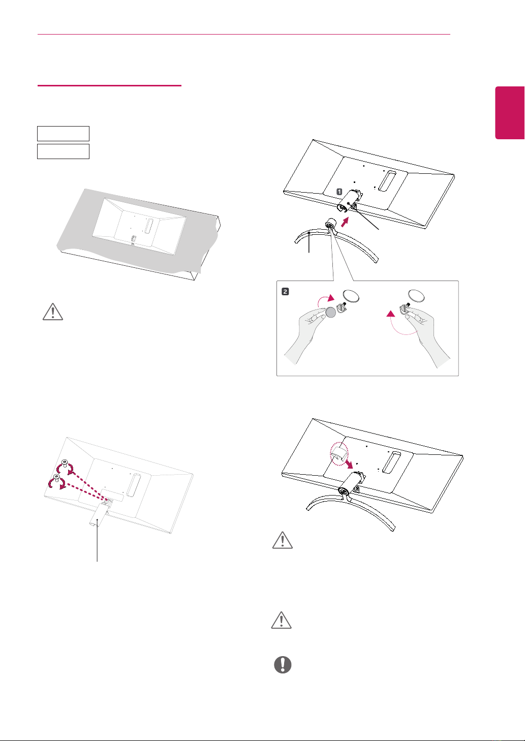
ASSEMBLING AND PREPARING
Moving and Lifting the Monitor
When moving or lifting the monitor, follow these in-
structions to prevent the monitor from being scratched
or damaged and to ensure safe transportation regard-
less of its shape or size.
yAs far as possible, avoid touching the monitor
screen. This may result in damage to the screen or
some of the pixels used to create images.
yIt is advisable to place the monitor in the original
box or packing material before attempting to
move it.
yBefore moving or lifting the monitor, disconnect
the power cord and all cables.
yHold the top and bottom of the monitor frame
firmly. Do not hold the screen itself.
yWhen holding the monitor, the screen should face
away from you to prevent it being scratched.
yWhen moving the monitor, avoid any strong shock
or vibrations to the product.
yWhen moving the monitor, keep it upright, never
turn the monitor on its side or tilt it sideways.
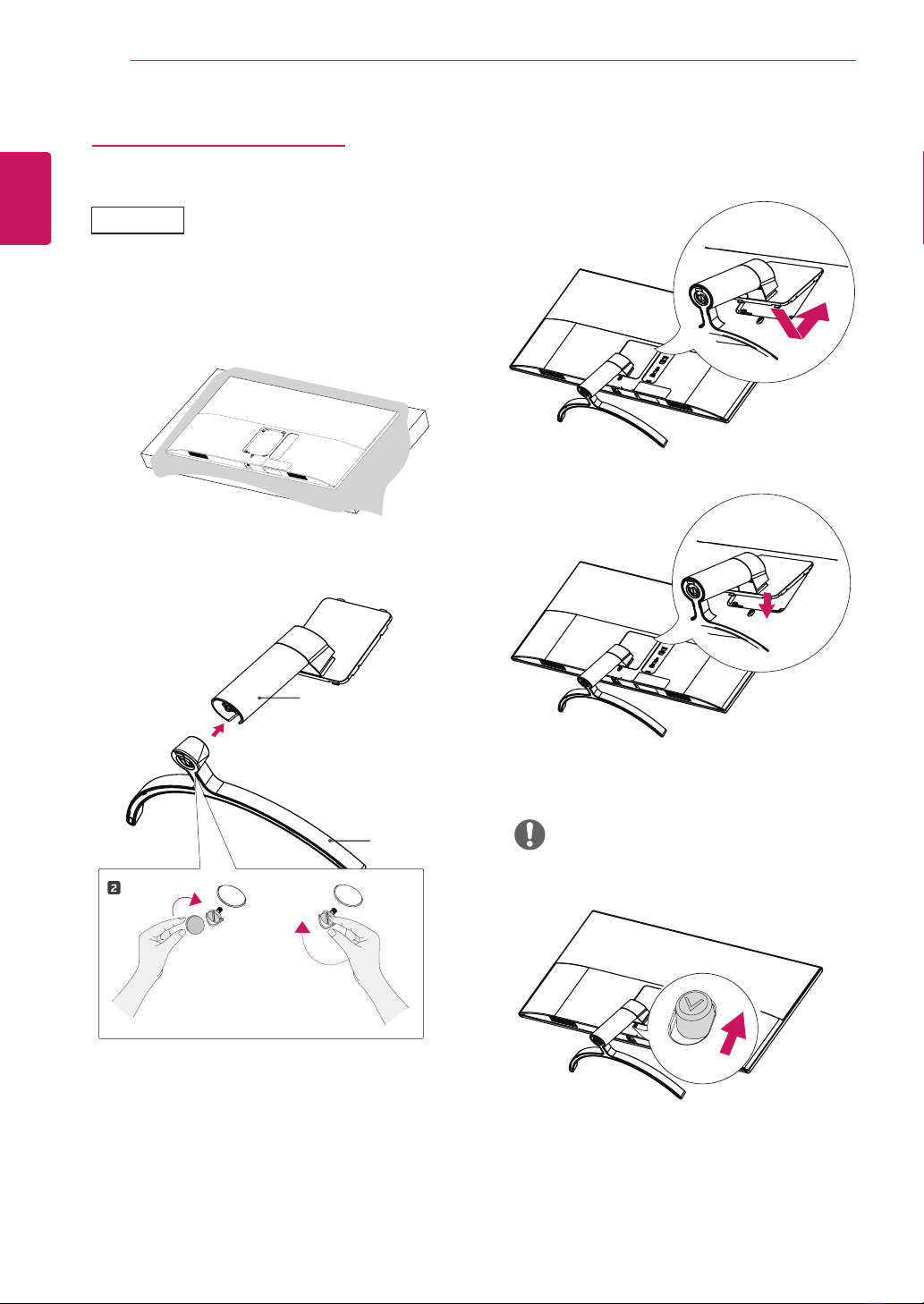
CAUTION
yIf you use the monitor panel without the stand
base, its joystick button may cause the monitor to
become unstable and fall, resulting in damage to
the monitor or human injury. In addition, this may
cause the joystick button to malfunction.
29WK500
29WK50S
34WK500