8
ENG
ENGLISH
ASSEMBLING AND PREPARING
Using the Kensington security system
The Kensington security system connector is
located at the back of the Monitor set. For more
information of installation and using, refer to the
manual supplied with the Kensington security
system or visit
http://www.kensington.com
.
Connect the Kensington security system cable
between the Monitor set and a table.
The Kensington security system is optional.
You can obtain it from most electronics stores.
NOTE
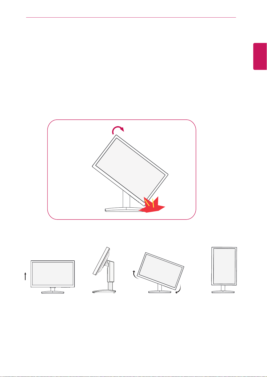
WARNING
When adjusting the angle of the
screen, do not put your finger(s)
in between the head of the m-
onitor and the stand body. You
can hurt your finger(s).
When adjusting the height of the
screen, do not put your finger(s)
inbetween the head of the mo-
nitor and the stand base. You
can hurt yourfinger(s).
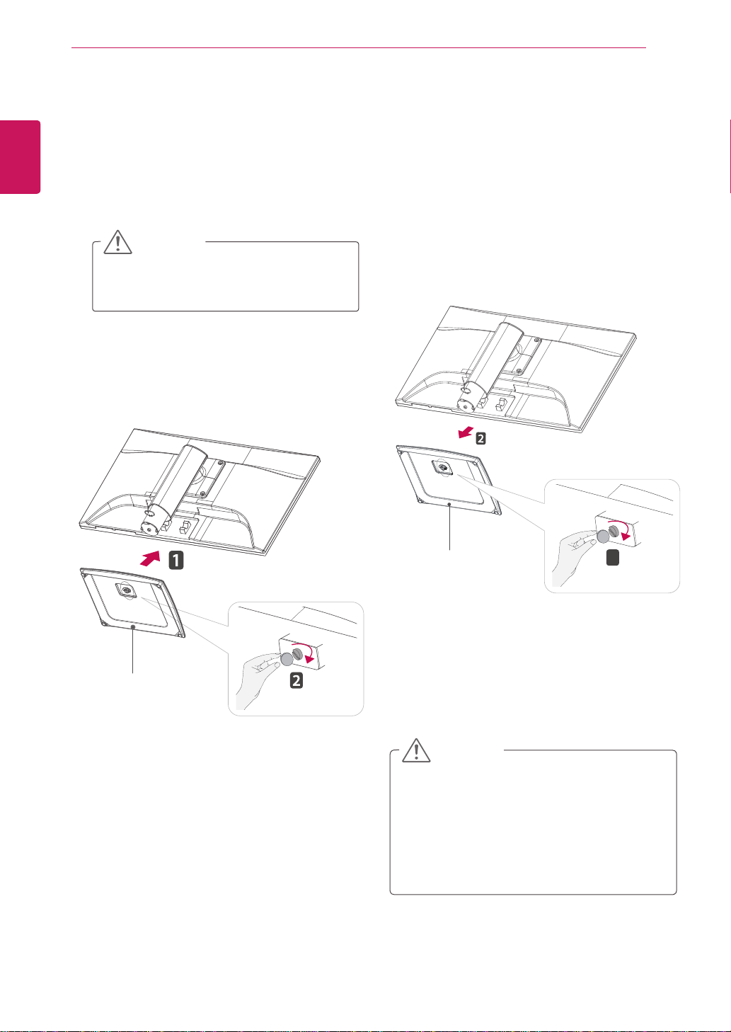
WARNING
You do not need to replace the Locking pin after it
is removed, to adjust its height.
ERGONOMIC
It is recommended that in order to maintain an erg-
onomic and comfortable viewing position, the forw-
ard tilt angle of the monitor should not exceed 5
degrees.