5
ENG
English
ASSEMBLING AND PREPARING
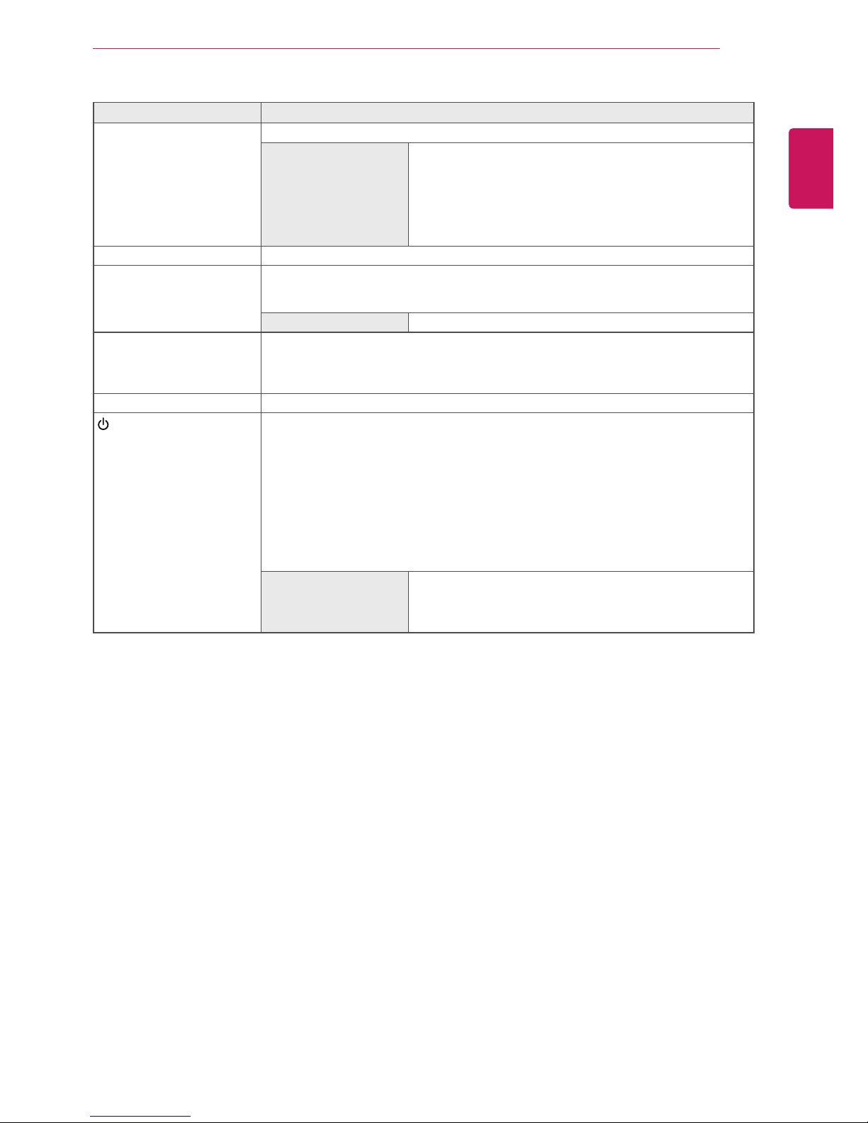
Button Description
MENU Activates the main menu.
OSD Lock/Unlock
Functions
Locks/unlocks the OSD screen.
yTo lock the OSD screen, press and hold the MENU button
for several seconds. The "OSD LOCKED" message will be
displayed and the screen will be locked.
yTo unlock the OSD screen, press and hold the MENU
button again for several seconds. The "OSD UNLOCKED"
message will be displayed and the screen will be unlocked.
VOLUME (Only PCoIP mode)
Adjust the volume of the Monitor set.(See p.21)
AUTO To adjust the monitor settings, press the AUTO button on the MONITOR SETUP OSD
menu (only supported for analog signal).
For optimal screen display, use the following resolution.
Optimal Resolution 1920 x 1080
INPUT Allows selection of the input signal.
yIf you connect the monitor to a computer using a D-SUB cable, select either the PCoIP
or D-SUB input signal.
yThe initial input signal is D-SUB.
EXIT Exits the OSD menu.
(Power Button)
yD-SUB Input: Power On/Off
yPCoIP Input
Monitor Off: Press the power button once then the monitor will be turned off after 5
seconds.
PCoIP Off: Press the power button twice then the monitor and PColP connection will
be disabled.
PCoIP On: Press the power button.
Remote PC Power Control: Press the power button for at least five seconds to turn
the PC on/off.
* Remote PC Power Control only works on the host PC where PCoIP host card is
installed and requires separate setup.
Power Indicator When the monitor is in operating mode, the power indicator
will turn Red (on mode).
When the monitor is in power saving mode, the power indica-
tor will blink Red.