LG StudioWorks 995SU User manual

P/NO : 3828TUL Printed in Korea
Please read this manual carefully before operating your set.
Retain it for future reference.
Record model number and serial number of the set.
See the label attached on the back cover and quote this
information to your dealer when you require service.
http://www.lge.co.kr
Color Monitor
User’s Guide
Benutzerhandbuch
Manuel d’utilisation
Guida Utente
Guia del Usuario
USER’S GUIDE StudioWorks 995E Color Monitor
StudioWorks
995SU
MODEL : SB995CU

995SU (SB995CU) Monitor
User’s Guide
StudioWorks

Notice
Copyright © LG Electronics Inc., 2000
All Rights Reserved
This document is protected by copyright with all rights reserved.
No part of the document may be reproduced or transmitted by
any means or in any form, without prior consent in writing from
LG Electronics Inc.
Trademark Acknowledgments
LG is a trademark of LG Electronics Inc.
IBM is a registered trademark and VGA is a trademark of
International Business Machines Corporation.

Introduction
Installation
Operation
Technical Information
Appendix
Table of Contents
Introduction
Important Precautions
Connecting the Monitor
Making use of USB (Universal Serial Bus)
Location and Function of Controls
Control Panel Function
On Screen Display (OSD) Control Adjustment
On Screen Display(OSD) Selection and Adjustment
Energy Saving Design
Low Radiation Compliance (MPR II) and DDC (Display Data Channel)
Video Memory Modes
Troubleshooting
Service
Specifications
Communications Regulation Information
Environmental Labelling of Personal Computers
i
A1
A9
A4
A2
A10
A12
A11
A15
A17
A18
A19
A20
See back of manual
See back of manual
A16
ENGLISH
A6

Introduction
A1
Features
Monitor Registration
The model and serial numbers are found on
the rear of this unit. These numbers are
unique to this unit and not available to
others. You should record requested
information here and retain this guide as a
permanent record of your purchase. Staple
your receipt here.
Date of Purchase :
Dealer Purchased From
:
Dealer Address :
Dealer Phone No. :
Model No. :
Serial No. :
Introduction
Thank you for purchasing a high resolution monitor. It will give you
high resolution performance and convenient reliable operation in a
variety of video operating modes.
The monitor is a 19 inches (18.0 inches viewable ) intelligent,
microprocessor based monitor compatible with most analog RGB (Red,
Green, Blue) display standards, including IBM PC®, PS/2®, Apple®,
Macintosh®, Centris®, Quadra®, and Macintosh II family.
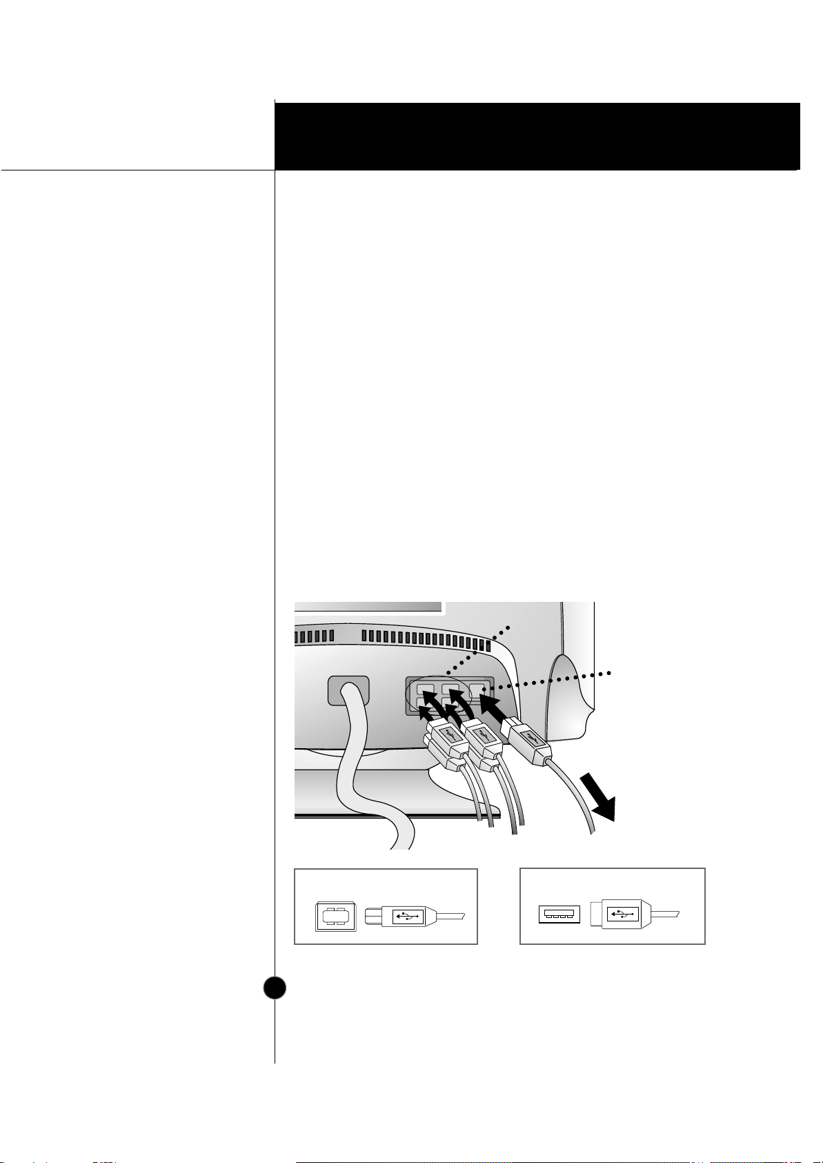
USB (Universal Serial Bus) ports at the back of the monitor are prepared
for the USB cable and hub. You can easily and flexibly connect USB-
designed devices-such as a mouse, keyboard or printer- to the monitor
for true Plug and Play function.
The monitor provides crisp text and vivid color graphics with VGA,
SVGA, XGA, and VESA Ergonomic modes (non-interlaced), and most
Macintosh compatible color video cards when used with the appropriate
adaptor. The monitor's wide compatibility makes it possible to upgrade
video cards or software without purchasing a new monitor.
Digitally controlled auto-scanning is done with the micro-processor for
horizontal scan frequencies between 30 and 96kHz, and vertical scan
frequencies between 50-160Hz. The microprocessor-based intelligence
allows the monitor to operate in each frequency mode with the
precision of a fixed frequency monitor.
This monitor is capable of producing a maximum horizontal resolution of
1600 dots and a maximum vertical resolution of 1200 lines. It is well
suited for CAD work and sophisticated windowing environments.
For low cost of monitor operation, this monitor is certified as meeting
the EPA Energy Star requirements, and utilizes the VESA Display Power
Management Signalling (DPMS) protocol for power saving during non-
use periods.

Operation
A2
Introduction
On Safety
Important Precautions
This unit has been engineered and manufactured to assure your
personal safety, but improper use can result in potential electrical
shock or fire hazard. In order not to defeat the safeguards
incorporated in this monitor, observe the following basic rules for its
installation, use, and servicing. Also follow all warnings and
instructions marked directly on your monitor.
Use only the power cord supplied with the unit. In case you use another
power cord, make sure that it is certified by the applicable national
standards if not being provided by the supplier.
If the power cable is
faulty in any way, please contact the manufacturer or the nearest
authorized repair service provider for a replacement.
Operate the monitor only from a power source indicated in the
specifications of this manual or listed on the monitor. If you are not sure
what type of power supply you have in your home, consult with your dealer.
Overloaded AC outlets and extension cords are dangerous. So are frayed
power cords and broken plugs. They may result in a shock or fire hazard.
Call your service technician for replacement.
Do not Open the Monitor
There are no user serviceable components inside.
There are Dangerous High Voltages inside, even when the power is
OFF.
Contact your dealer if the monitor is not operating properly.
To Avoid Personal Injury :
Do not place the monitor on a sloping shelf unless properly secured.
Use only a stand recommended by the manufacturer.
Do not try to roll a stand with small casters across thresholds or deep
pile carpets.
To Prevent Fire or Hazards:
Always turn the monitor OFF if you leave the room for more than a
short period of time. Never leave the monitor ON when leaving the
house.
Keep children from dropping or pushing objects into the monitor's
cabinet openings. Some internal parts carry hazardous voltages.

A3
Introduction
On Installation
On Cleaning
On Repacking
Important Precautions
Do not add accessories that have not been designed for this monitor.
During a lightning storm or when the monitor is to be left unattended
for an extended period of time, unplug it from the wall outlet.
Do not bring magnetic devices such as magnets or motors near the
picture tube.
Do not allow anything to rest upon or roll over the power cord, and do not
place the monitor where the power cord is subject to damage.
Do not use this monitor near water such as near a bathtub, washbowl,
kitchen sink, laundry tub, in a wet basement, or near a swimming pool.
Monitors are provided with ventilation openings in the cabinet to allow the
release of heat generated during operation. If these openings are blocked,
built-up heat can cause failures which may result in a fire hazard.
Therefore, NEVER:
Block the bottom ventilation slots by placing the monitor on a bed,
sofa, rug, etc.
Place the monitor in a built-in enclosure unless proper ventilation is
provided.
Cover the openings with cloth or other material.
Place the monitor near or over a radiator or heat source.
Unplug the monitor before cleaning the face of the picture tube.
Use a slightly damp (not wet) cloth. Do not use an aerosol directly on
the picture tube because overspray may cause electrical shock.
Do not throw away the carton and packing materials. They make an
ideal container in which to transport the unit. When shipping the unit
to another location, repack it in its original material.

Installation
A4
Connection to any IBM
VGA PC compatible
system
Connecting the Monitor
Figure 1 shows the signal cable connections from the monitor to the
Video Graphics Array (VGA) port typical in an IBM PC or PC
compatible. This also applies to any graphics video card for PC-CAD
or workstation that has a 15 pin high density (3 row) d-Sub connector.
1. Power off both the monitor and PC.
2. Connect the 15 pin VGA connector of the supplied signal cable to the
matching input connector on the rear of the monitor. The connectors
will mate only one way. If you cannot attach the cable easily, turn the
connector upside down and try again. When mated, tighten the
thumbscrews to secure the connection.
3. Power ON the PC, then the monitor.
4. If you see the SELF DIAGNOSTICS message, check the signal cable
and connectors.
5. After using the system, power OFF the monitor, then the PC.
Figure 1.
Power Cord
Signal Cable
D-15P

Installation
A5
Connecting to an Apple
Macintosh PC
Connecting the Monitor
Figure 2 shows the connection to an Apple Macintosh, using a
separately purchased adapter.
1. Power OFF both the monitor and the PC.
2. Locate the appropriate MAC to VGA adapter block at your local
computer store. This adapter changes the high density 3 row 15 pin
VGA connector to the correct 15 pin 2 row connection to mate with
your MAC. Attach the other end of the signal cable to the side of the
adapter block with 3 rows.
3. Connect the attached adapter block/signal cable to the video output on
your MAC.
4. Power ON the PC, then the monitor.
5. If you see the SELF DIAGNOSTICS message, check the signal cable
and connectors.
6. After using the system, power OFF the monitor, then the PC.
Figure 2.
MAC6MAC6
Power Cord Signal Cable
D-15P
Adapter 15P

USB connection
A6
Making use of USB (Universal Serial Bus)
USB (Universal Serial Bus) is an innovation in connecting your different
desktop peripherals conveniently to your computer. By using the USB,
you will be able to connect your mouse, keyboard, printer, and other
peripherals to your monitor instead of having to connect them to your
computer. This will give you greater flexibility in setting up your system.
USB allows you to connect chain up to 120 devices on a single USB port,
and you can “hot” plug (attach them while the computer is running) or
unplug them while maintaining Plug and Plug auto detection and
configuration. This monitor has an integrated self-powered USB hub,
allowing up to 4 other USB devices to be attached it.
1. Connect the upstream port of the monitor to the downstream port of
the USB compliant PC or another hub using the USB cable (Computer
must have a USB port).
2. Connect the USB compliant peripherals to the downstream ports of
the monitor.
USB Upstream connector USB Downstream connector
USB upstream Port
USB downstream Ports
connect the cables from USB
compliant peripherals-such as
keyboard, mouse, printer, scanner, etc
To USB downstream
port of the USB
compliant PC or
another hub cable
keyboard
printer mouse
etc.
Installation

USB specifications
A7
Making use of USB (Universal Serial Bus)
Example of connection
keyboard
printer
scanner
monitor
computer
mouse
USB standard
Downstream power supply
Communication speed
USB port
Rev. 1.0 complied self-powered hub
500mA for each (MAX)
12 Mbps (full), 1.5 Mbps (low)
1 Upstream port
4 Downstream ports
NOTE
To activate the USB hub function, the monitor must be connected to a USB
compliant PC(OS) or another hub with the USB cable(enclosed).
When connecting the USB cable, check that the shape of the connector at the
cable side matches the shape at the connecting side.
When the monitor is not plugged into an electric socket, the peripherals
connected to the downstream ports will not operate.
Even if the monitor is in a power saving mode, USB compliant devices will
function when they are connected the USB ports(both the upstream and
downstream) of the monitor.
Installation

Installation
USB-Monitor Software
function
A8
Making use of USB (Universal Serial Bus)
As an added advantage, the monitor can be controlled from a
computer with a mouse or keyboard. Making adjustments to the
image size, position, screen color and operating parameters of the
monitor is easy with the USB-Monitor software (please refer to the
supplied disk).
To access the USB-Monitor software
function:
1. Click the right button of the mouse,
then select the Properties.
The Display Properties windows
appears, as shown in the figure.
2. Click the USB-Monitor.
You can select and adjust the Control
Options (General, Color and
Advanced).
3. When you are finished the making
changes, click the Save.
To reset the image without applying
changes, click the Default.
Degauss removes magnetic field
buildup that can be affect color purity
and convergence.
4. To close the window, click OK.
NOTE
USB-Monitor software function is supported Windows 98 and higher.
Properties
Display Properties

Operation
A9
Front View
Rear View
Location and Function of Controls
ID Label
D-Sub Signal Cable
AC Power
Socket
Power Button
Power Indicator
OSD Button
••
•
•
•
•
Digital Control Panel
USB upstream port
USB downstream ports
•

Operation
A10
Control Panel Function
Use this button to enter
or exit the on screen
display.
OSD Button
Use these buttons to
choose or adjust items
in the on screen display.
Buttons
Use this button to enter
a selection in the on
screen display.
SET Button
Use this button to turn
the monitor on or off.
Power Button
The power indicator light is shown in the
power button. This indicator lights up
green when the monitor operates
normally. If the monitor is in DPM (Energy
Saving) mode (stand-by/ suspend/power
off), this indicator color changes to amber.
Power Indicator
•• •
•
••
•••
Front Panel Controls

Operation
A11
On Screen Display (OSD) Control Adjustment
Making adjustments to the image size, position and operating
parameters of the monitor are quick and easy with the On Screen
Display Control system. A quick example is given below to familiarize
you with the use of the controls. Following section is an outline of the
available adjustments and selections you can make using the OSD.
To make adjustments in the On Screen Display, follow these steps:
Press the OSD Button, then the main menu of the OSD appears.
To acces a control, use the or Buttons. When the icon you
want becomes highlighted, press the SET Button.
Use the Buttons to adjust the item to the desired level.
Accept the changes by pressing the SET Button.
Exit the OSD by Pressing the OSD Button.
NOTE
Allow the monitor to stabilize for at least 30 minutes before making image
adjustment.
1
1
2
3
4
5
6
7
1
2
2
3
4
5
6
7
1
2
3
3
4
5
6
7
1
2
3
4
4
5
6
7
1
2
3
4
5
5
6
7

Operation
A12
On Screen Display(OSD) Selection and
Adjustment
You were introduced to the procedure of selection and adjusting an
item using the OSD system.
Listed below are the icons, icon names, and icon descriptions of the
items that are shown on the Menu.
OSD Adjust Description
BRIGHTNESS CONTRAST
66
92
COLOR
PRESET
TEMP
RED
GREEN
BLUE
6500K 9300K
POSITION
66
45
Brightness
Used to adjust the brightness of the
screen.
Contrast
Adjust the display to the contrast
desired.
PRESET
TEMP
RED
GREEN
BLUE
6500K/ 9300K
To appear the displays color
temperature.
•6500K:Slightly reddish white.
•9300K:Slightly bluish white.
User easily color set without
adjustment Red, Green and Blue
(R/G/B).
To set your own color levels.
Vertical Position
To move image up and down.
Horizontal Position
To move picture image left and
right.
BRIGHTNESS/CONTRAST
COLOR
POSITION

Operation
A13
On Screen Display(OSD) Selection and
Adjustment
OSD Adjust Description
SIZE
49
64
SHAPE
Vertical Size
To adjust image height.
Horizontal Size
To adjust image width.
Side Pincushion
To correct the bowing in and out of the
image.
Side pincushion balance
To correct the balance of both sides
bowing.
Trapezoid
To correct geometric distortion.
Parallelogram
This control adjusts for a skewing
of the screen image.
Tilt
To correct image rotation.
Corner Top
To correct the irregular distortion of
the displayed image.
Corner Bottom
To correct the irregular distortion of
the displayed image.
SIZE
SHAPE

Operation
A14
On Screen Display(OSD) Selection and
Adjustment
OSD Adjust Description
To manually demagnetize the
screen which may show some
image or color incorrectly.
SPECIAL
DEGAUSS ON
RECALL OFF
MOIRE H: 0 / V: 0
CONVERGENCE H: 50
54.4kHz/60.0Hz
USER MODE
DEGAUSS
If the monitor is operating in a
factory preset mode, this control
will reset the image to the factory
preset mode.
If the monitor is operating in a user
mode, this control has no effect.
RECALL
CLAMP
This item allows you to reduce the
moire (Moire is caused by
interference Horizontal Scan Line
with the periodical dot screen). It is
normally OFF(H:0/V:0).
The moire adjustments may affect
the focus of the screen.
The screen image may shake
slightly while the moire reduction
function is on.
MOIRE
This item allows you to adjust the
horizontal convergence.
The horizontal convergence control
adjust the alignment of the red and
blue horizontal fields.
CONVERGENCE
SPECIAL
VIDEO LEVEL 0.7V
DDC ON
LANGUAGE ENGLISH
OSD POSITION
CLAMP SEP
SETUP
This item is used to select the monitor's
input signal level. The normal level
used for most PC's is 0.7V.
When the screen suddenly gets
brightened or blurry, please select
1.0V and try again.
To select the DDC function(ON/OFF).
To choose the language in which
the control names are displayed.
To adjust position of the OSD
window on the screen.
In case of input SOG(Sync On
Green) Video Signal, the back
raster will appear the green. Then,
to select the SOG(Sync On Green)
in the clamp, will take you back to
the original back raster.
VIDEO LEVEL
DDC
LANGUAGE
OSD POSITION
SETUP

Technical Information
A15
Power Consumption
Energy Saving Design
This monitor complies with the EPA's Energy Star program, which is a
program designed to have manufacturers of computer equipment build
circuitry into their products to reduce power consumption during time of
non-use.
This monitor also goes into its energy saving mode if you exceed the
monitor's operating limits, such as the maximum resolution of 1600x1200
or the frequency refresh rates of 30-96kHz horizontal or 50-160Hz vertical.
When this monitor is used with a Green or EPA Energy Star PC, or a PC
with a screen blanking software following the VESA Display Power
Management Signalling (DPMS) protocol, this monitor can conserve
significant energy by reducing power consumption during periods of non-
use. When the PC goes into the energy saving mode, the monitor will go
into a suspended operation state, indicated by the Power LED light
changing from a green color to an amber color. After an extended period
in the suspended mode, the monitor will then enter a semi-OFF mode to
conserve more energy. In the semi-OFF mode or DPMS OFF mode as we
call it in our specifications, the Power LED will still show an amber color.
When you awaken your PC by hitting a key or moving the mouse, the
monitor will also awaken to its normal operating mode, indicated by the
green Power LED light. By following these conventions, the power
consumption can be reduced to the following levels:
Mode
Normal(Max.)
Stand-by
Suspend
Off
Hori.
Sync
On
Off
On
Off
Verti.
Sync
On
On
Off
Off
Video
Normal
Off
Off
Off
Power
Consumption
≤
150W
≤
8W
≤
8W
≤
3W
LED Color
Green
Amber
Amber
Amber

Technical Information
A16
Low Radiation Compliance
(MPR II)
DDC (Display Data
Channel)
Low Radiation Compliance (MPR II) and
DDC (Display Data Channel)
This monitor meets one of the strictest guidelines available today for low
radiation emissions, offering the user extra shielding and an antistatic
screen coating. These guidelines, set forth by a government agency in
Sweden, limit the amount of emission allowed in the Extremely Low
Frequency (ELF) and Very Low Frequency (VLF) electromagnetic range.
DDC is a communication channel over which the monitor automatically
informs the host system (PC) about its capabilities. This monitor has two
DDC function; DDC1 and DDC2B. DDC1 and DDC2B carry out uni-
directional communication between the PC and the monitor. Under these
situations, the PC sends display data to the monitor but not commands to
control the monitor settings.
NOTE
PC must support DDC functions to do this.
If your monitor is displaying a mono chrome image or the wrong resolution,
select the DDC OFF function.
This manual suits for next models
2
Table of contents
Other LG Monitor manuals