PICTURE CONTROL
Picture ize (Aspect Ratio)Control.........................53
Preset Picture ettings
- Picture Mode-Preset............................................55
- Auto Colour Tone Control
(Cool/Medium/Warm)
.............................................56
Manual Picture Adjustment
- Picture Mode-User Option................................57
- Colour Tone - User Option...............................58
-
Picture Improvement Technology
...................59
Advanced - Gamma .....................................................60
Advanced - Film Mode ................................................61
Advanced - Black(Darkness) Level...........................62
Picture Reset..................................................................63
Image ticking Minimization(I M) Method ..........64
Power aving Picture Mode .......................................65
Factory Reset.................................................................66
WATCHING TV /PROGRAMME CONTROL
Remote Control Key Functions..................................34
Turning on the TV....................................................... 38
Programme election ................................................. 38
Volume Adjustment......................................................38
Quick Menu .................................................................. 39
On creen Menus election and Adjustment ......40
Auto Programme Tuning ............................................ 41
Manual Programme Tuning ....................................... 42
Fine Tuning .....................................................................43
Assigning a tation Name..........................................44
Booster............................................................................45
Programme Edit ........................................................... 46
PICTURE CONTROL
WATCHING TV / PROGRAMME CONTROL
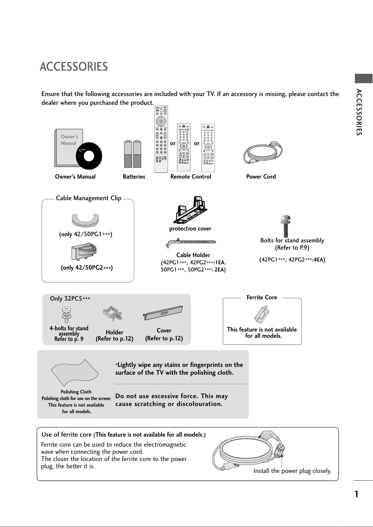
AACCCCEEOORRIIEE.....................................................1
2
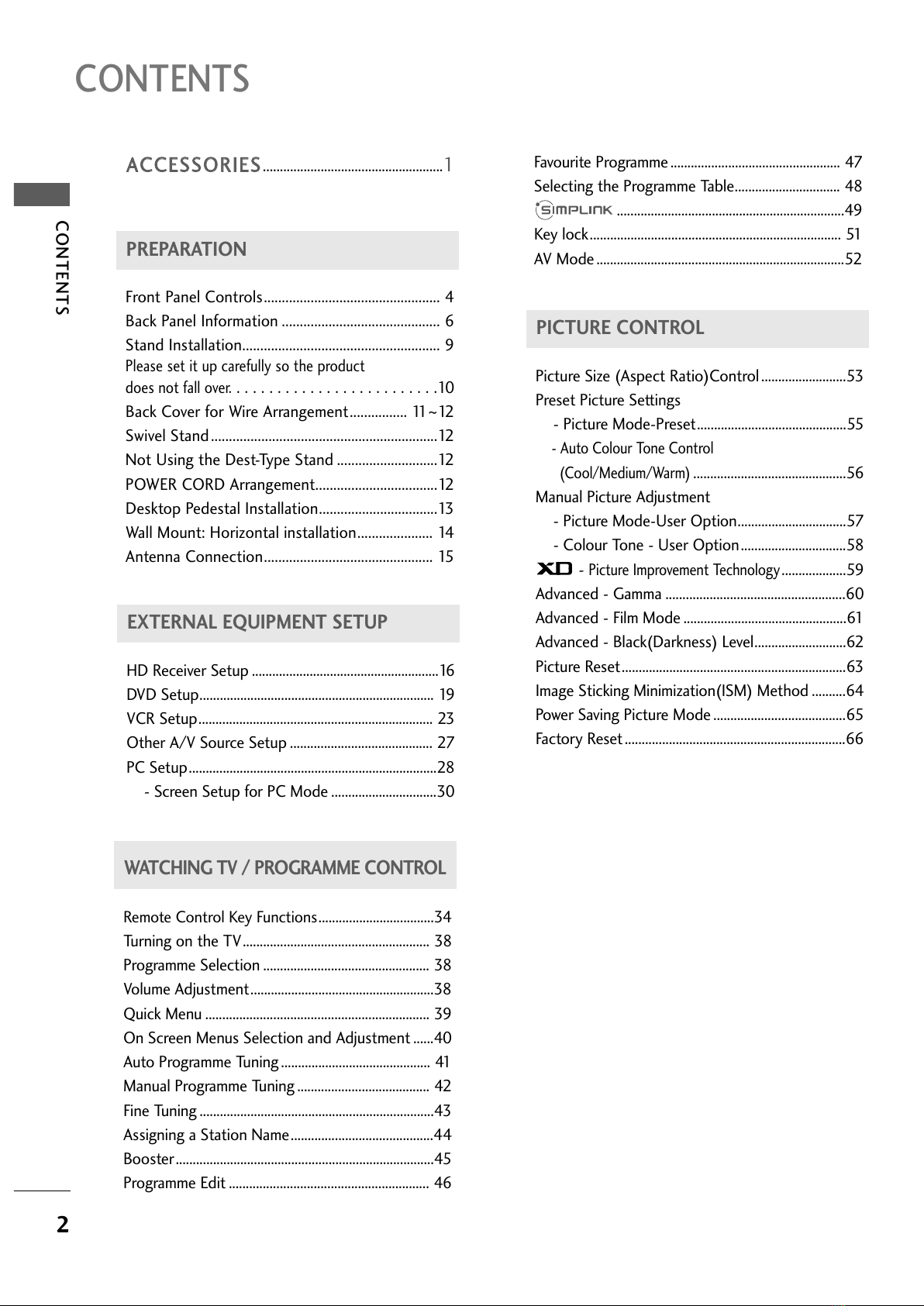
CONTENTS
CONTENTS
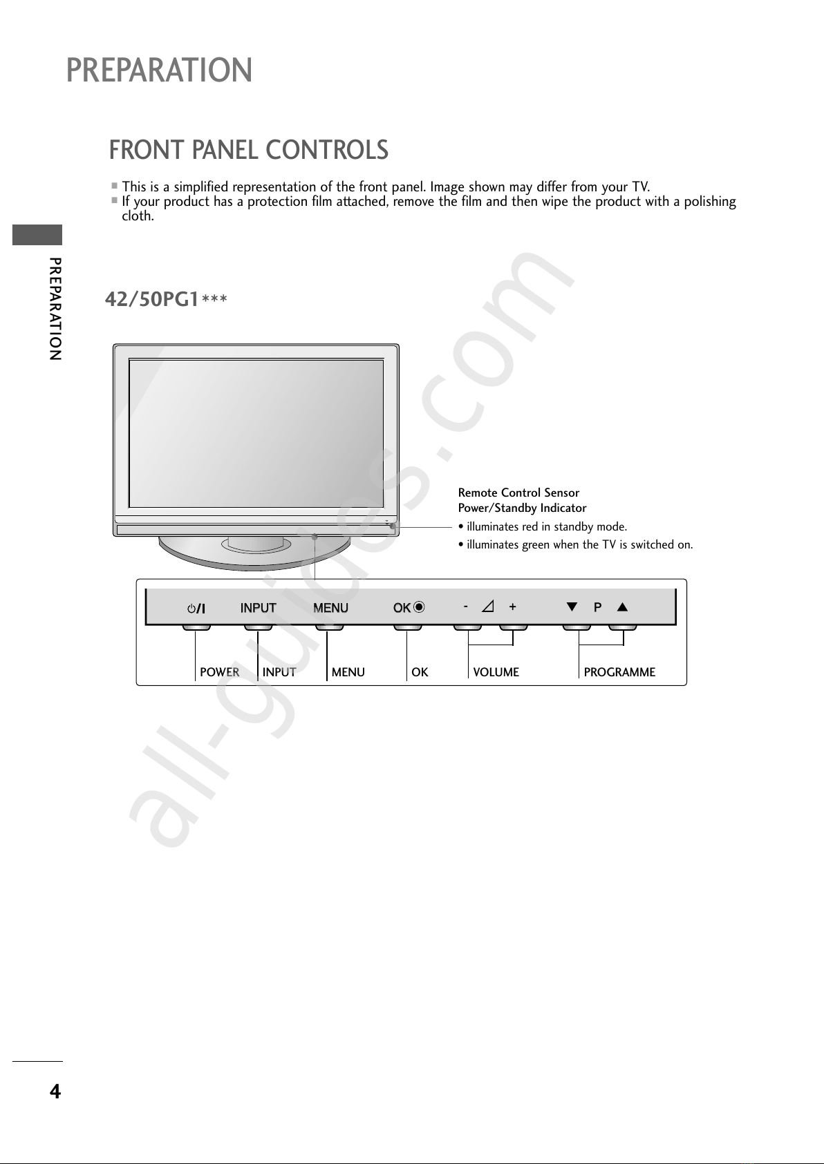
PREPARATION
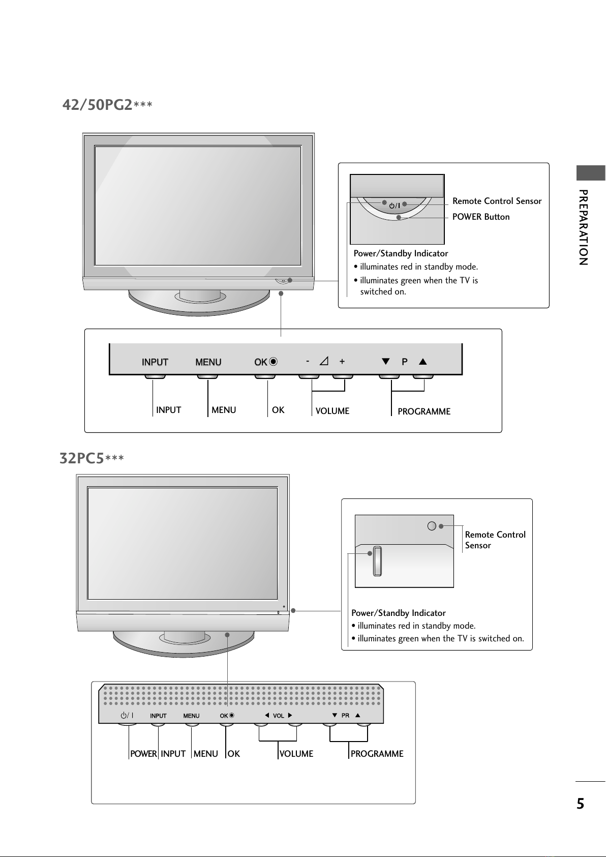
Front Panel Controls................................................. 4
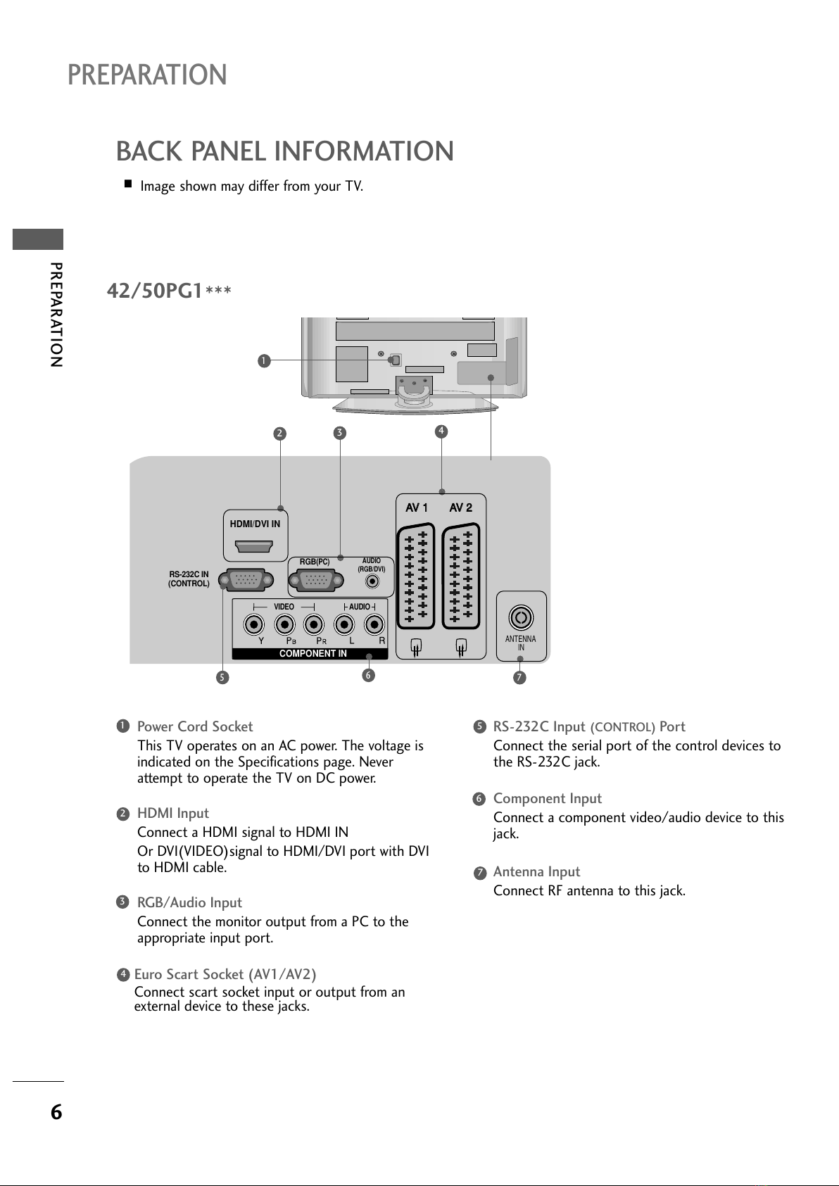
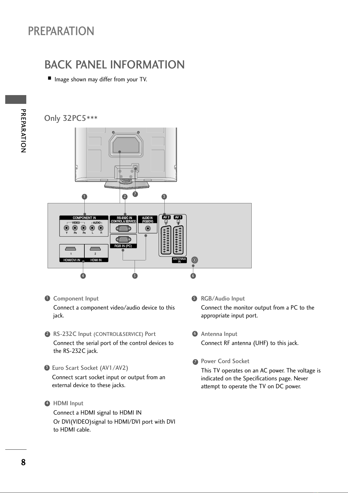
Back Panel Information ............................................ 6
tand Installation....................................................... 9
Please set it up carefully so the product
does not fall over.
. . . . . . . . . . . . . . . . . . . . . . . . .10
Back Cover for Wire Arrangement................ 11~12
wivel tand...............................................................12
Not Using the Dest-Type tand ............................12
POWER CORD Arrangement..................................12
Desktop Pedestal Installation.................................13
Wall Mount: Horizontal installation..................... 14
Antenna Connection............................................... 15
PREPARATION
EXTERNAL EQUIPMENT SETUP
HD Receiver etup .......................................................16
DVD etup..................................................................... 19
VCR etup..................................................................... 23
Other A/V ource etup .......................................... 27
PC etup.........................................................................28
- creen etup for PC Mode ...............................30
Favourite Programme .................................................. 47
electing the Programme Table............................... 48
...................................................................49
Key lock.......................................................................... 51
AV Mode .........................................................................52