LG 42PJ150 User manual

PLASMA TV
SERVICE MANUAL
CAUTION
BEFORE SERVICING THE CHASSIS,
READ THE SAFETY PRECAUTIONS IN THIS MANUAL.
CHASSIS : PD01A
MODEL : 42PJ150 42PJ150-ZE
North/Latin A erica http://aic.lgservice.co
Europe/Africa http://eic.lgservice.co
Asia/Oceania http://biz.lgservice.co
Internal Use Only
Printed in Korea
P/NO : MFL62881216(1006-REV00)

- 2 - LGE Internal Use OnlyCopyright ©2010 LG Electronics Inc. All rights reserved.
Only or training and service purposes
CONTENTS
CONTENTS ............................................................................................................................... 2
SAFETY PRECAUTIONS ...........................................................................................................3
SPECIFICATION.........................................................................................................................4
ADJUSTMENT INSTRUCTION ..................................................................................................7
TROUBLESHOOTING GUIDE .................................................................................................12
BLOCK DIAGRAM ...................................................................................................................23
EXPLODED VIEW ...................................................................................................................24
SVC. SHEET ................................................................................................................................

- 3 - LGE Internal Use OnlyCopyright ©2010 LG Electronics Inc. All rights reserved.
Only or training and service purposes
SAFETY PRECAUTIONS
Many electrical and mechanical parts in this chassis have special sa ety-related characteristics. These parts are identi ied by in the
Schematic Diagram and Exploded View.
It is essential that these special sa ety parts should be replaced with the same components as recommended in this manual to prevent
X-RADIATION, Shock, Fire, or other Hazards.
Do not modi y the original design without permission o manu acturer.
G n ral Guidanc
An isolation Transform r should always b us d during the
servicing o a receiver whose chassis is not isolated rom the AC
power line. Use a trans ormer o adequate power rating as this
protects the technician rom accidents resulting in personal injury
rom electrical shocks.
It will also protect the receiver and it's components rom being
damaged by accidental shorts o the circuitry that may be
inadvertently introduced during the service operation.
I any use (or Fusible Resistor) in this monitor is blown, replace it
with the speci ied.
When replacing a high wattage resistor (Oxide Metal Film Resistor,
over 1W), keep the resistor 10mm away rom PCB.
Keep wires away rom high voltage or high temperature parts.
Due to high vacuum and large sur ace area o picture tube,
extreme care should be used in handling th Pictur Tub .
Do not li t the Picture tube by it's Neck.
L akag Curr nt Cold Ch ck(Ant nna Cold Ch ck)
With the instrument AC plug removed rom AC source, connect an
electrical jumper across the two AC plug prongs. Place the AC
switch in the on position, connect one lead o ohm-meter to the AC
plug prongs tied together and touch other ohm-meter lead in turn to
each exposed metallic parts such as antenna terminals, phone
jacks, etc.
I the exposed metallic part has a return path to the chassis, the
measured resistance should be between 1MΩ and 5.2MΩ.
When the exposed metal has no return path to the chassis the
reading must be in inite.
An other abnormality exists that must be corrected be ore the
receiver is returned to the customer.
L akag Curr nt Hot Ch ck (S b low Figur )
Plug the AC cord directly into the AC outlet.
Do not us a lin Isolation Transform r during this ch ck.
Connect 1.5K/10watt resistor in parallel with a 0.15uF capacitor
between a known good earth ground (Water Pipe, Conduit, etc.)
and the exposed metallic parts.
Measure the AC voltage across the resistor using AC voltmeter
with 1000 ohms/volt or more sensitivity.
Reverse plug the AC cord into the AC outlet and repeat AC voltage
measurements or each exposed metallic part. Any voltage
measured must not exceed 0.75 volt RMS which is corresponds to
0.5mA.
In case any measurement is out o the limits speci ied, there is
possibility o shock hazard and the set must be checked and
repaired be ore it is returned to the customer.
L akag Curr nt Hot Ch ck circuit
1.5 Kohm/10W
To Instrument's
exposed
METALLIC PARTS
Good Earth Ground
such as WATER PIPE,
CONDUIT etc.
AC Volt-meter
IMPORTANT SAFETY NOTICE
0.15uF

- 4 - LGE Internal Use OnlyCopyright ©2010 LG Electronics Inc. All rights reserved.
Only or training and service purposes
SPECIFICATION
NOTE : Speci ications and others are subject to change without notice or improvement
.
VApplication Rang
This spec is applied to the PLASMA TV used PD01A Chassis.
V Sp cification
Each part is tested as below without special appointment.
(1) Temperature : 25 °C ± 5 °C (77 °F ± 9 °F), CST : 40 ± 5
(2) Relative Humidity: 65 % ± 10 %
(3) Power Voltage: Standard Input voltage (100 V - 240 V ~, 50 / 60 Hz)
* Standard Voltage o each product is marked by models.
(4) Speci ication and per ormance o each parts are ollowed each drawing and speci ication by part number in accordance with
BOM.
(5) The receiver must be operated or about 20 minutes prior to the adjustment.
VT st M thod
(1) Per ormance : LGE TV test method ollowed.
(2) Demanded other speci ication
Sa ety : CE, IEC speci ication
EMC : CE, IEC
VModul Sp cification
(1) 42” HD
Display Screen Device
Aspect Ratio
PDP Module
Operating Environment
Storage Environment
Input Voltage
1
2
3
4
5
6
No Item Speci ication Remark
106 cm (42 inch) Wide Color Display Module
16:9
PDP42 T1####,
RGB Closed(Well) Type, Glass Filter(38 %)
Pixel Format: 1365 horiz. By 768 ver.
1) Temp. : 0 deg ~ 40 deg
2) Humidity : 20 % ~ 80 %
3) Temp. : -20 deg ~ 60 deg
4) Humidity : 10 % ~ 90 %
AC 100 V - 240 V ~, 50 / 60 Hz
PDP
LGE SPEC.
Maker LG

- 5 - LGE Internal Use OnlyCopyright ©2010 LG Electronics Inc. All rights reserved.
Only or training and service purposes
VMod l G n ral Sp cification
No Item Speci ication Remarks
1 Market Albania, Austria, Belgium, Bosnia, Bulgaria, 36 Country
Coratia, Czech, Denmark, Estonia, Finland,
France, Germany, Greece, Hungary, Ireland,
Italy, Kazakhstan, Latvia, Lithuania,
Luxembourg, Morocco, Netherlands, Norway,
Poland, Portugal, Romania, Russia, Serbia,
Slovenia, Spain, Sweden, Slovakia,
Switzerland, Turkey, Ukraine, UK
2 Broadcasting system 1) PAL/SECAM BG EU (PAL Market)
2) PAL/SECAM DK
3) PAL Ⅰ/Ⅱ
4) SECAM L/L’
5) DVB T
6) DVB C
3 Receiving system Analog : Upper Heterodyne
Digital : COFDM, QAM
4 Scart Jack (2EA) PAL, SECAM Scart 1 Jack is Full scart and support
RF-OUT(Analoge)
Scart 2 jack is Hal scart and support
MNT-OUT.
5 Video Input (1EA) PAL, SECAM, NTSC Side AV except PJ20, PK20
6 Component Input (1EA) Y/Cb/Cr, Y/ Pb/Pr rear
7 RGB Input RGB-PC Analog (D-Sub 15Pin) except PJ20, PK20
8 HDMI Input (4EA) HDMI-PC HDMI1/DVI, HDMI2, HDMI3
HDMI-DTV 1ea : PJ20
2ea : PK30, PK20, PJ60, PJ50, PJ30
3ea : PK50, PK70
9 Audio Input (3 EA) RGB/DVI Audio, Component, AV L/R Input
10 SPDIF Out(1 EA) SPDIF Out
11 USB For SVC, S/W Download, X-Studio, DivX PJ30 doesn’t support Divx
PK20, PJ20 only or SVC
12 Bluetooth Bluetooth Phone(JPEG, MP3), Only 50/60PK550
Bluetooth Headset(mono, stereo) Pro ile : A2DP, BIP, FTP, GAVDP, HSP, OPP

- 6 - LGE Internal Use OnlyCopyright ©2010 LG Electronics Inc. All rights reserved.
Only or training and service purposes
VChroma & Brightn ss (Optical)
(1) (With 38 % Glass Filter) 42T1 module
No Item Min Typ Max Unit Remark
1. White peak brightness 315 - cd/m2(*) Peak Brightness Mode
-1/100 white Window pattern
(Typically 1% Window size)
-100IRE (255Gray)
-Picture: Vivid (Medium)
-Input: HDMI-PC(1920*1080 60Hz)
*Peak Brightness Condition may Slightly
di erent between sets.
148 161 -25/100 white Window pattern
2. White average brightness 46 50 cd/m2- 100% Window White Pattern
- 100IRE(255Gray)
- Picture: Vivid(Medium )
3. Brightness uni ormity -10 0 +10 %
- 85IRE(216Gray) 100% Window White Pattern
- Picture: Vivid(Medium)
4. Color White X 0.270 0.285 0.300 - White : 85IRE(216Gray) 100% Window
Coordinate Y 0.283 0.293 0.303 White Pattern
Red X 0.635 0.640 - - R/G/B : 100IRE(255Gray) 100% Window
Y 0.318 0.330 0.345 White Pattern
Green X 0.242 0.300 0.305 - Picture: Vivid(Medium )
Y 0.595 0.600 - - 100% Window
Blue X - 0.150 0.158
Y - 0.065 0.075
5. Color coordinate uni ormity -0.01 Average +0.01 - 85IRE 100% Window White Pattern
- Picture: Vivid(Medium)
6. Contrast ratio at dark room 100k: 1 1,000k: 1 -1/100 white window pattern(Peak mode)
-100IRE(255Gray)
-Picture: Vivid(Medium)
-Input: HDMI-PC (1920*1080 60Hz)
7. Color Cool X 0.261 0.276 0.291 - 85IRE 100% Window White Pattern
Temperature Y 0.268 0.283 0.298 Warm : ColorGamut => WIDE
Medium X 0.270 0.285 0.300 Cool : Color temperature C30
Y 0.278 0.293 0.308 Meduum : Color temperature 0
Warm X 0.298 0.313 0.328 Warm : Color temperature W30
Y 0.314 0.329 0.344

- 7 - LGE Internal Use OnlyCopyright ©2010 LG Electronics Inc. All rights reserved.
Only or training and service purposes
ADJUSTMENT INSTRUCTION
1. Application
This spec. sheet is applied to all o the PD01A chassis.
2. Sp cification
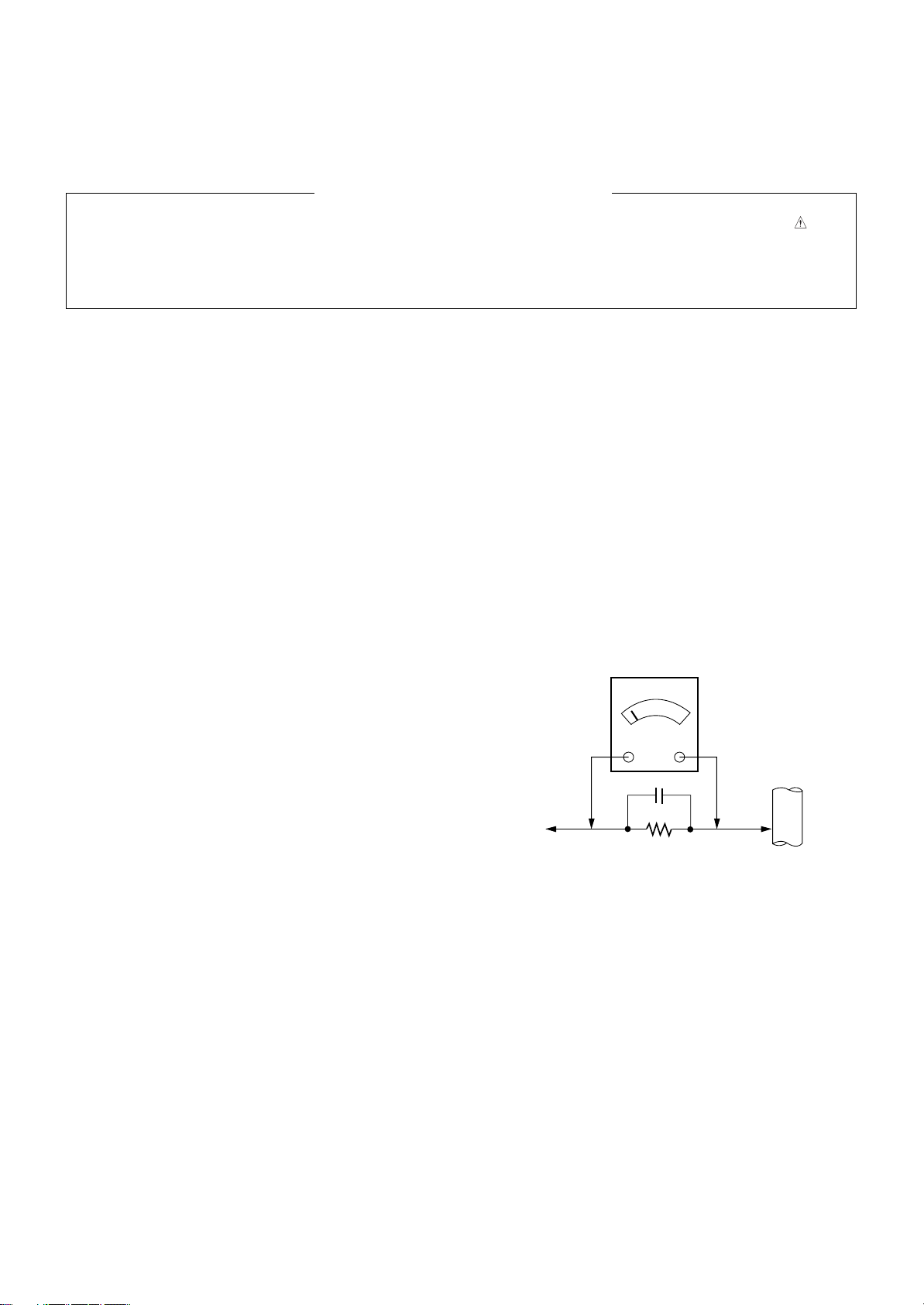
[Caution: Th modul k ping condition]
- The module keeping condition: The normal temperature
condition(more than 15 °C)
--> Immediately the line supply.
- The module keeping condition: 0 °C
--> The module must be kept or more than 2 hours at the
normal temperature.
- The module keeping condition: -20 °C
--> The module must be kept or more than 3 hours at the
normal temperature.
- The case o Gu-mi actory at the winter season.
--> The module must be kept or more than 5 minutes at
the heating zone(40 °C ~ 45 °C).
(1) The adjustment is according to the order which is
designated and which must be ollowed, according to the
plan which can be changed only on agreeing.
(2) I there is no speci ic designation, the adjustment must be
per ormed in the circumstance o 25 °C ± 5 °C o
temperature and 65 % ± 10 % o relative humidity.
(3) The input voltage o the set must keep 100 V ~ 240 V,
50 / 60 Hz.
(4) Input signal Unit: Product Speci ication Standard.
(5) The set must be operated or about 5 minutes prior to the
adjustment.
OA ter turning on RGB Full Window pattern in HEAT-RUN
Mode, the receiver must be operated.
OEnter into HEAT-RUN MODE
1) Press the ‘POWER ON’ button on R/C or adjustment.
2) Press the ‘ADJ’ button on R/C and enter EZ ADJUST
Select “7. Test Pattern” by using D/E(CH +/-) and press
ENTER(V)
Select “White” by using F/G(VOL +/-) and press
ENTER(V)
- Set heat run should be activated without a signal generator.
- Single color patterns (RED / BLUE / GREEN) o HEAT RUN
MODE are used to check a plasma panel.
- Caution: I you turn on a still screen more than 20 minutes
(Especially digital pattern, cross hatch pattern), an a ter
image may be made in the black level part o the screen.
[Caution]
- Use ‘power on’ button o a service R/C to power on TV set.
- Do not connect any external input cable i there is no any
speci ics.
3. Updat S/W using Auto Download
through th USB
Caution: S/W version o USB ile (xxx.epk) must be bigger than
one which is downloaded previously.
(1) Insert the USB stick to the USB socket
(2) A downloaded ile in USB stick will be detected
automatically.
(3) I S/W version o USB ile (xxx.epk) is bigger than one
which is downloaded previously, the message, “Copying
iles rom memory”, will appear.
(4) I an update procedure was completed, TV set will be
turned o and on automatically.
(5) I TV set is turned on, check an updated version.
* I a downloaded version is more bigger than one o which
TV set had, TV set can lost channel data. In this case,
you have to scan channels again.
4. Aft r Downloading S/W, Adjust
TOOL OPTION
(1) Push “IN-START” button on a service R/C.
(2) Select “Tool Option 1” and Push “OK” button.
(3) Put the number o a below table in order o a su ix o the
“Tool Option(X)”.
(Each model has a di erent number.)

5. ADC Calibration Proc dur
(1) Input the component (480i/Horizontal Color Bar) signal to a
TV set.
1) Input Signal Timing : Component 480i
(Other external connection is unnecessary except the
component be ore executing ADC calibration.)
2) Input Signal Pattern
@ MODEL: 209 in Pattern Generator(480i Mode)
@ PATTERN : 65 in Pattern Generator(MSPG-925
SERISE)
(2) Push “ADJ” button on a service R/C.
(3) Enter internal ADC mode by selecting ‘5. ADC Calibration’.
(4) I you select ‘Start’ on a dialog box o the screen, ADC
calibration will be begun.
Caution: Don’t connect any external input cable except the
component input(480i/Horizontal_Color_Bar) to adjust
ADC calibration
OAuto ADC Calibration Map(RS-232C)
# Adjust Sequence
- aa 00 00 [Enter Adjust Mode]
- xb 00 40 [Component1 Input (480i)]
- ad 00 10 [Adjust 480i Comp1]
- xb 00 60 [RGB Input (1024*768)]
- ad 00 10 [Adjust 1024*768 RGB]
- aa 00 90 End Adjust mode
6. EDID Download Proc dur
(1) Push “ADJ” button on a service R/C.
(2) Enter EDID auto download mode by selecting ‘8. EDID
D/L’.
(3) I you select ‘Start’ on a dialog box o the screen, EDID
download will be begun automatically.
(4) Press ‘EXIT’ button on a service R/C.
(5) EDID Data
1) HDMI (HD Models, 256 bytes)
2) RGB (HD Models, 128 bytes)
OEDID Data detailing (ⓐ, ⓑ, ⓒ, ⓓ, ⓔ, ⓕ)
- 8 - LGE Internal Use OnlyCopyright ©2010 LG Electronics Inc. All rights reserved.
Only or training and service purposes
<Horizontal Color Bar pattern>
NO Item
CMD1
AA00
01
D
A
CMD2 Data0
Enter
Adjust MODE
Adjust
‘Mode In’
When trans er the ‘Made
In’, Carry the command.
Automatically adjustment
(The use o a internal
pattern)
ADC
Adjust
ADC Adjust

ⓐProduct ID
ⓑSerial No
=> Controlled on production line
ⓒMonth, Year
=> Controlled on production line:
ⓓModel Name
ⓔChecksum
=> Changeable by total EDID data
ⓕHDMI Port No.
OAuto EDID Download Map(RS-232C)
7. PCMCIA CARD Ch ck
You must adjust DTV 29 Channel and insert PCMCIA CARD
to socket.
- I PCMCIA CARD works normally, video signals will appear
on screen.
But it works abnormally, “No CA module” will appear on
screen.
[Caution: Set up “RF mode” be ore launching products.
8. POWER Supply Unit PCB Ass’y
Va/Vs Voltag Adjustm nt
Caution: Both Vs and Va voltage adjustment are necessary.
8-1. Va/Vs Adjustm nt Proc dur
(1) Connect positive(+) terminal o DMM to Vs/Va pin, connect
negative(-) terminal to GND.
(2) Turning ‘Vs/Va Adjust’ and adjust Vs/Va voltages to a
value which is written on a right/top label o a module.
(deviation ; ±0.5V)
[Caution]
- Each Power Supply Unit PCB assembly must be checked by
check JIG set. (Because power PCB Ass’y damages to PDP
Module, especially be care ul)
- Set up “RF mode(noise)” be ore a voltage adjustment.
- Test equipment: DMM 1EA
9. Whit Balanc Adjustm nt
Caution: Press the POWER ON KEY on R/C be ore W/B
adjustment.
OTest Equipment
Color Analyzer (CS-1000, CA-100+(CH.10), CA-210(CH.10))
OPlease adjust CA-100+ / CA-210 by CS-1000 be ore
measuring
You should use Channel 10 which is Matrix compensated
(White, Red, Green, Blue revised) by CS-1000 and adjust
in accordance with White balance adjustment coordinate.
- 9 - LGE Internal Use OnlyCopyright ©2010 LG Electronics Inc. All rights reserved.
Only or training and service purposes
NO Item
CMD1
AA00
1000
E
A
CMD2 Data0
Enter
download
MODE
Download
‘Mode In’
When trans er the ‘Made
In’, Carry the command.
Automatically download
(The use o a internal
Data)
Download
EDID data and
Model option
download
MODEL
EDID MODEL
PRODUCT_ID FUNCTION
ALL Model LG DTV 0001(0x01, 0x00) Analog
ALL Model LG DTV 0001(0x01, 0x00) Digital
FHD HD
HDMI1 0xE2 0xB4 0xAF 0xB4
HDMI2 0xE2 0xA4 0xAF 0xA4
HDMI3 0xE2 0x94 0xAF 0x94
HDMI4 - - - -
RGB 0x62 0x2F

9-1. Color T mp ratur Standards According
to CSM and Modul (TBD)
9-2. Chang Targ t Luminanc and Rang
of th Auto Adjustm nt W/B Equipm nt
9-3. Whit Balanc Adjustm nt Coordinat
and Color T mp ratur
[PC ( or communication through RS-232C) ? UART Baud
rate : 115200 bps
9-4. Automatic W/B Adjustm nt
(1) Internal PATTERN should be used when W/B is adjusted.
Connect to auto controller like below.
(2) Start White-Balance adjustment, then the ull white window
pattern will appear on the screen.
(3) Adjust in the place where the in lux o light like loodlight
around is blocked.
(illumination is less than 10ux).
(4) Measure and adjust a ter sticking the Color Analyzer (CA-
100+, CA210 ) to the side o the module.
OAuto W/B Adjustment Map(RS-232C)
RS-232C COMMAND
[ CMD ID DATA ]
Wb 00 00 White Balance Start
Wb 00 FF White Balance End
9-5. Manual W/B Adjustm nt
(1) Execute the zero calibration o CA-100+ / CA-210.
(2) Press the ‘ADJ’ button on a service R/C and enter EZ
ASJUST by selecting ‘6. White Balance’.
(3) Then, 216 gray pattern will appear on the screen.
(4) Change the R/G/B-Gain as passing in 3 color coordinates
and temperatures, COOL, MEDIUM and WARM.
< Temperature: COOL >
- R-Cut / G-Cut / B-Cut is set to 64
- Control R-Gain and G-Gain.
- Each gain is limited to 192
< Temperature: MEDIUM >
- R-Cut / G-Cut / B-Cut is set to 64
- Control R-Gain and G-Gain.
- Each gain is limited to 192
< Temperature: WARM >
- R-Cut / G-Cut / B-Cut is set to 64
- Control G-Gain and B-Gain.
- Each gain is limited to 192
(5) Press ‘EXIT’ button on a service R/C
- 10 - LGE Internal Use OnlyCopyright ©2010 LG Electronics Inc. All rights reserved.
Only or training and service purposes
20Range
50Target luminance
128646464B Cut
128646464G Cut
128646464R Cut
50H3
60H3
25519219219200jJcjiB Gain
25519219219200jeJbjhG Gain
25519219219200jdJajgR Gain
WarmMedCoolWarmMedCool
MAX
CENTER
(DEFAULT)
Min
RS-232C COMMAND
[CMD ID DATA]
6500KWarm
9300KMedium
11000KCool
PLASMACSM

<Notic > Modul H at-Run Condition for W/B
(1) The adjustment must be per ormed in the circumstance o
25 °C ± 5 °C o temperature and 65 % ± 10 % o relative
humidity i there is no any speci ics.
(2) Be ore an W/B adjustment, the module which will be used
should be placed in the circumstance o 15 °C ~ 25 °C or
above 2 hours.
(3) I a module was placed in the circumstance o below 15
°C, it should be placed in the circumstance o 15 °C ~ 25
°C or above 2 hours or be run or above 5 minutes in an
aging environment o 60 °C.
(4) Be ore an W/B adjustment, TV set should be run or 5
minutes at least.
10. S rial Numb r Download
10-1. Download Proc dur
(1) Press “Power on” button o a service R/C.(Baud rate :
115200 bps)
(2) Connect RS232-C Signal Cable.
(3) Write Serial number through RS-232C.
(4) Check the serial number at the Diagnostics o ‘SETUP’
menu. (Re er to below).
Caution : Don’t download HDMI/RGB EEPROM to write a
model name. Model name dois unnecessary
because this model use ‘Tool Option’ to call a model
name.
10-2. Signal TABLE
CMD : A0h
LENGTH : 85~94h (1~16 bytes)
ADH : EEPROM Sub Address high (00~1F)
ADL : EEPROM Sub Address low (00~FF)
Data : Write data
CS : CMD + LENGTH + ADH + ADL + Data_1 + ... +
Data_n
Delay : 20ms
10-3. Command S t
[Description]
FOS De ault write : <7mode data> write
Vtotal, V_Frequency, Sync_Polarity, Htotal, Hstart, Vstart,
0, Phase
Data write : Model Name and Serial Number write in
EEPROM,.
11. CI+ K y Download
11-1. Download Proc dur
(1) Press "Power on" button o a service R/C.(Baud rate :
115200 bps)
(2) Connect RS232-C Signal Cable.
(3) Write CI+ Key through RS-232-C.
(4) Check whether the key was downloaded or not at ‘In Start’
menu. (Re er to below)
12. Ch ck Information
(Serial No. & Model name)
(1) Push the menu button in DTV mode.
(2) Select the SETUP -> Diagnostics -> To set
(3) Check the Serial Number
- 11 - LGE Internal Use OnlyCopyright ©2010 LG Electronics Inc. All rights reserved.
Only or training and service purposes

- 12 - LGE Internal Use OnlyCopyright ©2010 LG Electronics Inc. All rights reserved.
Only or training and service purposes
TROUBLESHOOTING GUIDE

- 13 - LGE Internal Use OnlyCopyright ©2010 LG Electronics Inc. All rights reserved.
Only or training and service purposes

- 14 - LGE Internal Use OnlyCopyright ©2010 LG Electronics Inc. All rights reserved.
Only or training and service purposes

- 15 - LGE Internal Use OnlyCopyright ©2010 LG Electronics Inc. All rights reserved.
Only or training and service purposes

- 16 - LGE Internal Use OnlyCopyright ©2010 LG Electronics Inc. All rights reserved.
Only or training and service purposes

- 17 - LGE Internal Use OnlyCopyright ©2010 LG Electronics Inc. All rights reserved.
Only or training and service purposes

- 18 - LGE Internal Use OnlyCopyright ©2010 LG Electronics Inc. All rights reserved.
Only or training and service purposes

- 19 - LGE Internal Use OnlyCopyright ©2010 LG Electronics Inc. All rights reserved.
Only or training and service purposes

- 20 - LGE Internal Use OnlyCopyright ©2010 LG Electronics Inc. All rights reserved.
Only or training and service purposes
This manual suits for next models
1
Table of contents
Other LG Plasma TV manuals