LG 42PX4D User manual

Please
read
this
manual
carefully
and
completely
before
operating
your
TV.
Retain
this
manual
for
future
reference.
Record
model
number
and
serial
number
of
the
TV
in
the
spaces
provided
below.
See
the
label
attached
on
the
back
cover
and
relate
this
information
to
your
dealer
if
you
require
service.
Model
Number
:
Serial
Number
:
MODELS:
42PX4D/42PX5D
42PX4D-UB/42PX5D-UB
LG
Electronics
U.S.A.,
Inc.
TM
R
TruSurround
XT
PLASMA
TV
OWNER'S
MANUAL

2
Plasma
TV
Warning/Caution
WARNING/CAUTION:
TO
REDUCE
THE
RISK
OF
ELECTRIC
SHOCK
DO
NOT
REMOVE
COVER
(OR
BACK).
NO
USER
SERVICEABLE
PARTS
INSIDE.
REFER
TO
QUALIFIED
SERVICE
PERSONNEL.
The
lightning
flash
with
arrowhead
symbol,
within
an
equilateral
triangle,
is
intended
to
alert
the
user
to
the
presence
of
uninsulated
"dangerous
voltage"
within
the
product's
enclosure
that
may
be
of
suffi-
cient
magnitude
to
constitute
a
risk
of
electric
shock
to
persons.
The
exclamation
point
within
an
equilateral
triangle
is
intended
to
alert
the
user
to
the
presence
of
important
operating
and
maintenance
(servicing)
instructions
in
the
literature
accompanying
the
appli-
ance.
WARNING/CAUTION:
TO PREVENT
FIRE
OR
SHOCK
HAZARDS,
DO
NOT
EXPOSE
THIS
PRODUCT
TO
RAIN
OR
MOISTURE.
FCC
NOTICE
?
A
Class
B
digital
device
This
equipment
has
been
tested
and
found
to
comply
with
the
limits
for
a
Class
B
digital
device,
pursuant
to
Part
15
of
the
FCC
Rules.
These
limits
are
designed
to
provide
reasonable
protection
against
harmful
interference
in
a
residential
installation.
This
equipment
generates,
uses
and
can
radiate radio
frequency
energy
and,
if
not
installed
and
used
in
accordance
with
the
instructions,
may
cause
harmful
interference
to
radio
communications.
However,
there
is
no
guarantee
that
interference
will
not
occur
in
a
particular
installation.
If
this
equipment
does
cause
harmful
interference
to
radio
or
television
reception,
which
can
be determined
by
turning
the
equipment
off
and
on,
the
user
is
encouraged
to
try
to
correct
the
interference
by
one
or
more
of
the
following
measures:
-
Reorient
or
relocate
the
receiving
antenna.
-
Increase
the
separation
between
the
equipment
and
receiver.
-
Connect
the
equipment
into
an
outlet
on a
circuit
different
from
that
to
which
the
receiver
is
connected.
-
Consult
the
dealer
or
an
experienced
radio/TV
technician
for
help.
?
Any
changes
or
modifications
not
expressly
approved
by
the
party
responsible
for
compli-
ance
could
void
the
user's
authority
to
operate
the
equipment.
.CAUTION:
Do
not
attempt
to
modify this
product
in
any
way
without
written
authorization
from
LG
Electronics.
Unauthorized
mod-
ification
could
void
the
user's
authority
to
operate
this
product.
COMPLIANCE:
The
responsible
party
for
this
product's
compliance
is:
LG
Electronics
U.S.A.,
Inc
1000
Sylvan
Avenue,
Englewood
Cliffs,
NJ
07632
1-800-243-0000
http://www.lgusa.com
WARNING/CAUTION
WARNING/CAUTION
TO
REDUCE
THE
RISK
OF
FIRE
AND
ELECTRIC
SHOCK,
DO
NOT
EXPOSE
THIS
PRODUCT
TO
RAIN
OR
MOISTURE.
W
Warning/Caution
arning/Caution

Owner's
Manual
3
TV
Guide
On
Screen
Notices
for
U.S.A.
TV
Guide
On
Screen
Notices
for
U.S.A.
In
the
United
States,
TV
GUIDE
and
other
related
marks
are
registered
marks
of
Gemstar-TV
Guide
International,
Inc.
and/or
one
of
its
affiliates.
In
Canada,
TV
GUIDE
is
a
registered
mark
of
Transcontinental
Inc.,
and
is
used
under
license
by
Gemstar-TV
Guide
International,
Inc.
The
TV
Guide
On
Screen
system
is
protected
by
one
or
more
of
the
following
issued
United
States
patents
6,498,895,
6,418,556,
6,331,877; 6,239,794;
6,154,203;
5,940,073; 4,908,713; 4,751,578; 4,706,121.
The
TV
Guide
On
Screen
system
is
manufactured
under
license
from
Gemstar-TV
Guide
International,
Inc.
and/or
one
of
its
affiliates.
Digital
Cable
Compatibility
Digital
Cable
Compatibility
This
digital
television
is
capable
of
receiving
basic
analog,
digital
basic
and
digital
premium
cable
television
programming
by
direct
connection
to
a
cable
system
providing
such
programming.
A
security
card
provided
by
your
cable
operator
is
required
to
view
encrypted
digital
programming.
Cable
operator
enhanced
program
(For
example,
electronic
program
guide
provided
by
the
cable
operator),
and
data
enhanced
television
service
may
require
the
use
of
a
set
top
box.
For
more
information
con-
tact
your
local
cable
operator.
Use
of
the
CableCARDTM
TradeMark.
"CableCARDTM
is
a
trademark
of
Cable
Television
Laboratories,
Inc."
Trademark
Notice
Aux
Etats
Unis
TV
GUIDE
et
d'autres
marques
relatives
sont
des
marques
deposees
de
Gemstar-TV
Guide
International,
Inc.
et/ou
d'une
de
ses
societes
affiliees.
Au
Canada
TV
GUIDE
est
une
marque
deposee
de
Transcontinental
Inc.,
utilisee
sous
licence
de
Gemstar-TV
Guide
International,
Inc.
Le
systeme
TV
Guide
On
Screen
est
fabriques
sous
licence
de
Gemstar-TV
Guide
International,
Inc.
et/ou
d'une
de
ses
societes
affiliees.
Le
systeme
TV
Guide
On
Screen
est
proteges
par
un
ou
plusieurs
brevets
emis
aux
Etats
Unis,
comme
le
6,498,895,
6,418,556, 6,331,877; 6,239,794; 6,154,203;
5,940,073;
4,908,713; 4,751,578;
4,706,121.
License
Notice
Patent
Notice

4
Plasma
TV
Safety
Instructions
IMPORTANT
SAFETY
INSTRUCTIONS
Important
safety
instructions
shall
be
provided
with
each
apparatus.
This
information
shall
be
given
in
a
separate
booklet
or
sheet,
or
be
located
before
any
operating
instructions
in
an
instruction
for
installation
for
use
and
supplied
with
the
appara-
tus.
This
information
shall
be
given
in
a
language
acceptable
to
the
country
where
the
apparatus
is
intended
to
be
used.
The
important
safety
instructions
shall
be
entitled
"Important
Safety
Instructions".
The
following
safety
instructions
shall
be
includ-
ed
where
applicable,
and,
when
used,
shall
be
verbatim
as
follows.
Additional
safety
information
may
be
included
by
adding
statements
after
the
end
of
the
following
safety
instruction
list.
At the
manufacturer's
option,
a
picture
or
drawing
that
illus-
trates
the
intent
of
a
specific
safety
instruction
may
be
placed
immediately
adjacent
to
that
safety
instruction
:
1.
Read
these
instructions.
2.
Keep
these
instructions.
3.
Heed
all
warnings.
4.
Follow
all
instructions.
5.
Do
not
use
this
apparatus
near
water.
6.
Clean
only
with
dry
cloth.
7.
Do
not
block
any
ventilation
openings.
Install
in
accordance
with the
manufacturer's
instructions.
8.
Do
not
install
near
any
heat
sources
such
as
radiators,
heat
registers,
stoves,
or
other
apparatus
(including
ampli-
fiers)that
produce
heat.
9.
Do
not
defeat
the
safety
purpose
of
the
polarized
or
grounding-type
plug.
A
polarized
plug
has
two
blades
with
one
wider
than
the
other.
A
grounding
type
plug
has
two
blades
and
a
third
grounding
prong,
The
wide
blade
or
the
third
prong
are
provided
for
your
safety.
If
the
provided
plug
does
not
fit
into
your
outlet,
consult
an
electrician
for
replacement
of
the
obsolete
outlet.
10.
Protect
the
power
cord
from
being
walked
on
or
pinched
particularly
at
plugs,
convenience
receptacles,
and
the
point
where
they
exit
from
the
apparatus.
11.
Only
use
attachments/accessories
specified
by
the
manufacturer.
12.
Use
only
with
the
cart,
stand,
tripod,
bracket,
or
table
specified
by
the
manufacturer,
or
sold
with
the
apparatus.
When
a
cart
is
used,
use
caution
when
moving
the
cart/apparatus
combination
to
avoid
injury
from
tip-over.
Safety
Instructions
Safety
Instructions
PORTABLE
CART
WARNING

Owner's
Manual
5
Safety
Instructions
13.
Unplug
this
apparatus
during
lightning
storms
or
when
unused
for
long
periods
of
time.
14.
Refer
all
servicing
to
qualified
service
personnel.
Servicing
is
required
when
the
apparatus
has
been
damaged
in
any
way,
such
as
power-supply
cord
or
plug
is
damaged,
liquid
has
been
spilled
or
objects
have
fallen
into
the
apparatus,
the
apparatus
has
exposed
to
rain
or
moisture,
does
not
operate
normally,
or
has
been
dropped.
15.
CAUTION
concerning
the
Power
Cord
:
Most
appliances
recommend
they
be
placed
upon
a
dedicated
circuit;
that
is,
a
single
outlet
circuit
which
powers
only
that
appliance
and
has
no
additional
outlets
or
branch
circuits.
Check
the
specification
page
of
this
owner's
manual
to
be
certain.
Do
not
overload
wall
outlets.
Overloaded
wall
outlets,
loose
or
damaged
wall
outlets,
extension
cords,
frayed
power
cords,
or
damaged
or
cracked
wire
insulation
are
dangerous.
Any
of
these
conditions
could
result
in
electric
shock
or
fire.
Periodically
examine
the
cord
of
your
appliance,
and
if
its
appearance
indicates
damage
or
deterioration,
unplug
it,
discontinue
use
of
the
appliance,
and
have
the
cord
replaced
with
an
exact
replacement
part
by
an
authorized
servicer.
Protect
the
power
cord
from
physical
or
mechanical
abuse,
such
as
being
twisted,
kinked,
pinched,
closed
in
a
door,
or
walked
upon.
Pay
particular
attention
to
plugs,
wall
outlets,
and
the
point
where
the
cord
exits
the
appliance.
16.
Outdoor
Use
Marking
:
WARNING
-
To
Reduce
The
Risk
Of
Fire
Or
Electric
Shock,
Do
Not
Expose
This
Appliance
To
Rain
Or
Moisture.
17.
Wet
Location
Marking
:
Apparatus
shall
not
be
exposed
to
dripping
or
splashing
and
no
objects
filled
with
liquids,
such
as
vases,
shall
be
placed
on
the
apparatus.

6Plasma
TV
Contents
After
reading
this
manual,
keep
it
handy
for
future
reference.
Warning/Caution................................2
DigitalCableCompatibility.........................3
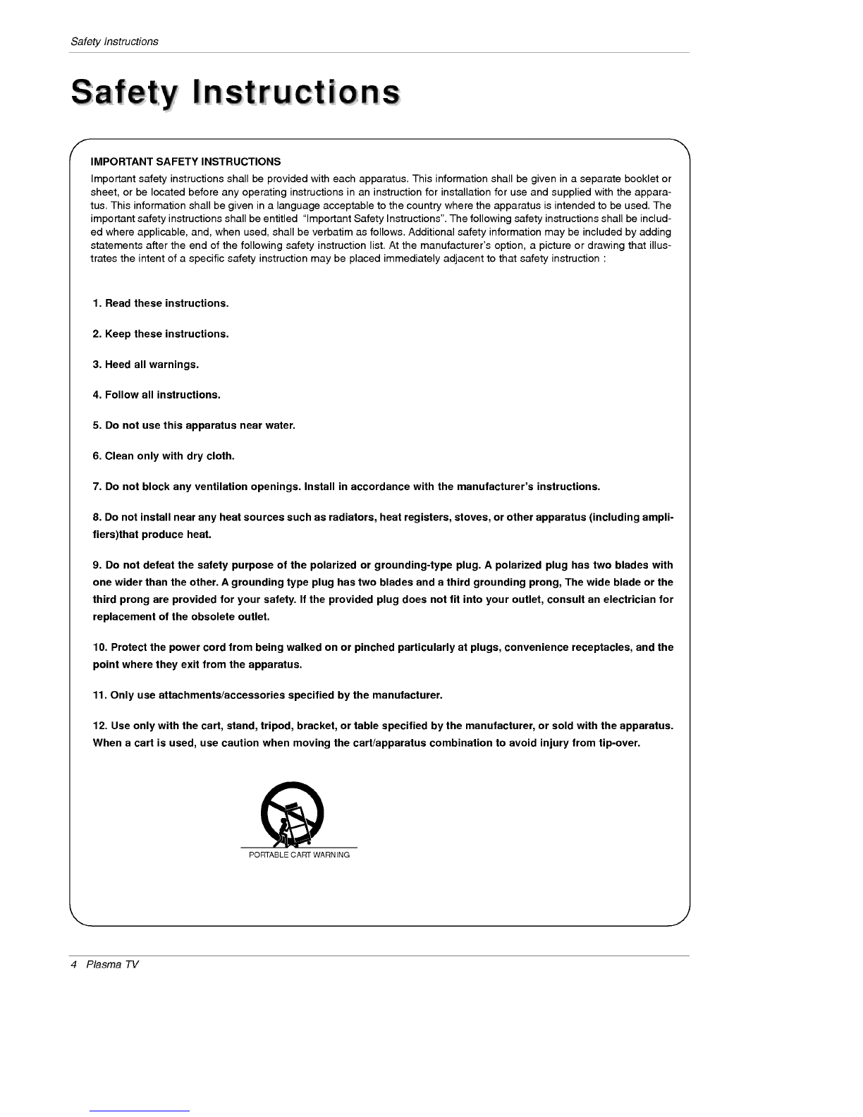
SafetyInstructions.............................4~5
Introduction
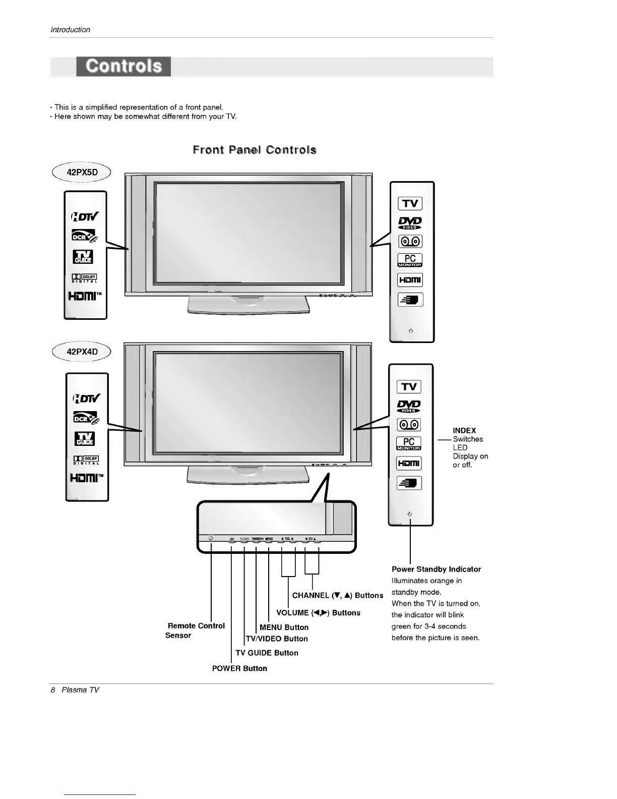
Controls...............................8
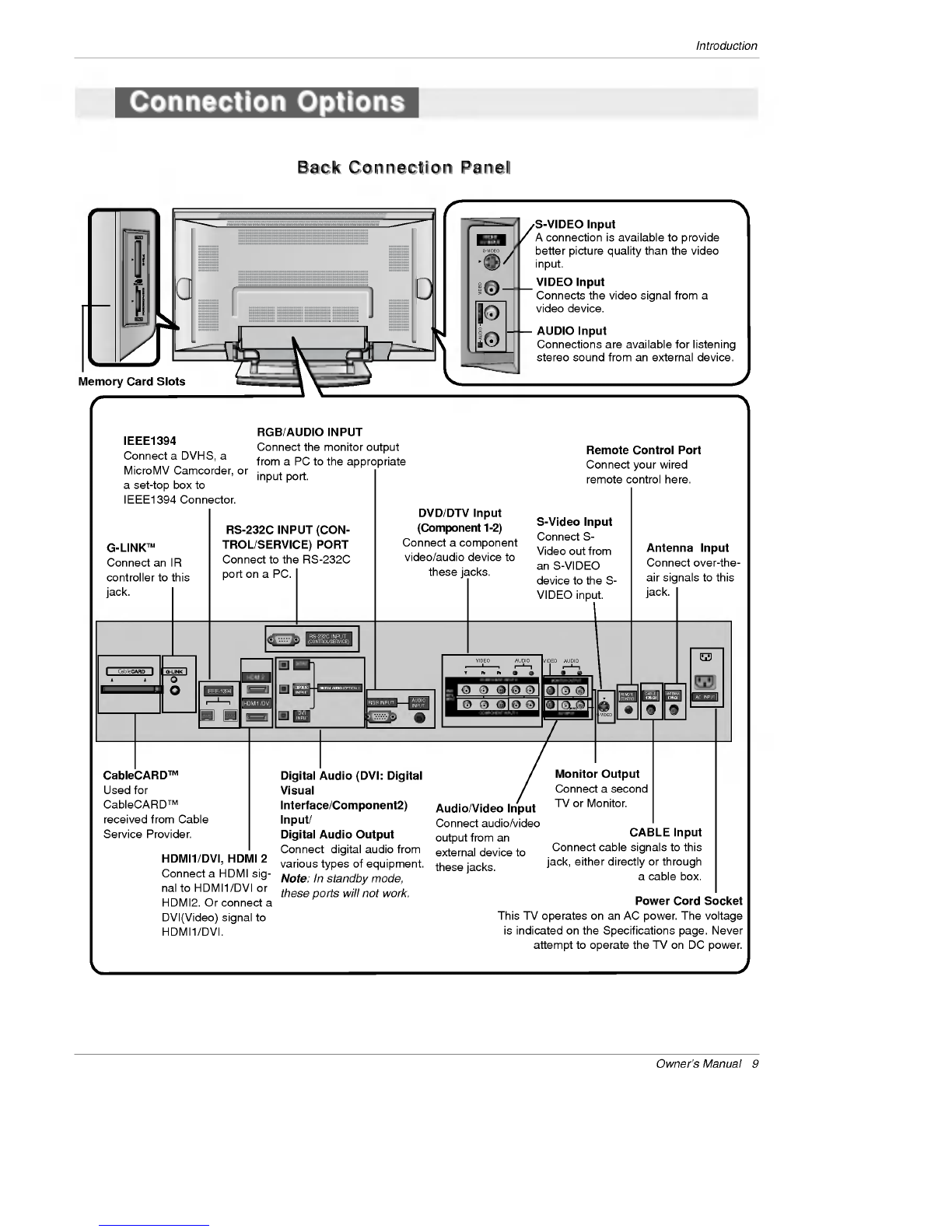
ConnectionOptions......................9
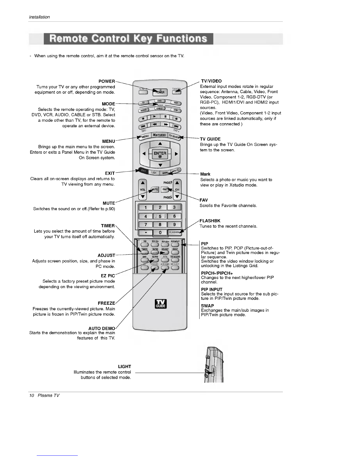
RemoteControlKeyFunctions.
. . . . . . . .
.10~11
Installation
Accessories.............................12
InstallationInstructions..................12~13
Joining
the
TV
assembly
to
the
wall
to
protect
the
set
tum-
bling.................................12
Swivelfunction..........................13
External
Equipment
Connections
..... ....
.14~19
AntennaorCableConnection
. . . . . . . . . .
.14~15
VCRSetup...........................15
ExternalA/VSourceSetup................16
DVDSetup............................16
CableCARDTMSetup.....................17
HDSTBSetup.........................17
PCSetup.............................18
MonitorOutSetup......................19
DigitalAudioOutput.....................19
HDMI...............................20~22
TVGuideOnScreenSetup..............23~32
IEEE1394................................33~40
TVGuideOnScreenTMSystem
. . . . . . . . . . . .
.41~59
Operation
TurningtheTVOn........................60
TV
Setup
On-screen
Menus
Language
Selection
. . . . . .
.61
Setup
Menu
Options
EZScan(ChannelSearch)................62
ManualScan..........................62
ChannelEdit...........................63
DTVSignalStrength.....................63
ChannelLabelSetup....................64
MainPictureSourceSelection
. . . . . . . . . . . .
.64
InputLabel............................64
Video
Menu
Options
EZPicture............................65
Manual
Picture
Control
(Custom
Option)
. . . . .
.65
ColorTemperatureControl................65
VideoReset...........................65
Audio
Menu
Options
AudioLanguage........................66
EZSoundRite/EZSound.................66
Manual
Sound
Control
(Custom
Option)
. . . . .
.66
FrontSurround.........................67
TVSpeakersOn/OffSetup................67
BBE.................................68
Stereo/SAPBroadcastsSetup.
. . . . . . . . . . . .
.68
Time
Menu
Options
AutoClockSetup.......................69
ManualClockSetup.....................69
On/OffTimerSetup.....................69
SleepTimer/AutoOff....................70
Option
Menu
Features
AspectRatioControl.....................71
Cinema3:2ModeSetup..................71
Caption...............................72
Caption/Text..........................72
CaptionOption........................73
ISMMethod...........................74
LowPower............................75
AutoDemo............................75
Lock
Menu
Options
LockMenuOptions......................76
ParentalLockSetup.....................77
CableCARDTM
Function
Cablemenuoptions.....................78
Scrambledchannel......................78
CableChannelList......................79
EmergencyAlertMessage................79
..........................80~85
Remote
Control
PIP
(Picture-in-Picture)/POP/Twin
Picture
. . . . . .
.86
WatchingPIP/POP/TwinPicture.
. . . . . . . . . .
..86
Selecting
an
Input
Signal
Source
for
PIP/Twin
Picture
.
.86
SwappingPIP/TwinPicture................86
TVProgramSelectionforPIP.
. . . . . . . . . . . .
.86
MovingthePIPsubpicture................87
Adjusting
Main
and
Sub
Picture
Sizes
for
Twin
Picture
.
.87
POP(Picture-out-of-Picture:
Channel
Scan)
. . .
.87
APM(AdaptivePictureMode)................88
Brief
Info.
...............................89
EZMute................................90
Freeze&Magnify.........................90
ScreenSetupforPCmode..................91
ExternalControlDeviceSetup.
. . . . . . . . . . . . . .
.92~97
IRCodes................................98~99
ProgrammingtheRemote.....................100
ProgrammingCodes.....................101~102
TroubleshootingChecklist.....................103
Maintenance................................104
ProductSpecifications........................105
Warranty...............................107~108
Contents
Contents
Setup
and
Operation
Checklist
Setup
and
Operation
Checklist
Setup
and
Operation
Checklist
(See
pages
14~19
for
available
connection
and
operational
setup
options.)
1.
Unpack
TV
and
all
accessories.
2.
Connect
all
external
video
and
audio
equipment.
see
pages
15~19.
3
Install
batteries
in
remote
control.
See
page
11.
4.
Turn
TV
on.
See
page
60.
5.
Turn
video
source
equipment
on.
6.
Select
viewing
source
for
TV.
See
pages
64.
7.
Fine-tune
source
image
and
sound
to
your
personal
prefer-
ence
or
as
required
by
source.
See
pages
65~
68.
8.
Additional
features
set
up
See
Contents
above.

Owner's
Manual
7
Introduction
Introduction
Introduction
What
is
a
Plasma
Display
Panel
(PDP)?
A
plasma
display
panel
is
the
latest
display
technology
and
the
best
way
to
achieve
flat
panel
displays
with
excellent
image
quality
and
large
screen
sizes
that
are
easily
viewable.
The
PDP
can
be
thought
of
as
a
descendant
of
the
neon
lamp
and
it
can
be
also
be
viewed
as
a
series
of
fluorescent
lamps.
How
does
it
work?
PDP
is
an
array
of
cells,
known
as
pixels,
which
are
comprised
of
3
sub
pixels,
corresponding
to
the
colors
red,
green,
and
blue.
Gas
in
a
plasma
state
is
used
to
react
with
phosphors
in
each
sub-pixel
to
produce
colored
light
(red,
green,
or
blue).
These
phos-
phors
are
the
same
types
used
in
Cathode
Ray
Tube
(CRT)
devices
such
as
televisions
and
common
computer
monitors.
You
get
the
rich,
dynamic
colors
that
you
expect.
Each
sub-pixel
is
individually
controlled
by
advanced
electronics
to
produce
over
16
million
different
colors.
All
of
these
mean
that
you
get
perfect
images
that
are
easily
viewable
in
a
display
that
is
less
than
5
inches
thick.
160°
-
Wide
angle
range
of
vision
Your
flat
panel
plasma
screen
offers
an
exceptionally
broad
viewing
angle
--
over
160
degrees.
This
means
that
the
display
is
clear
and
visible
to
viewers
anywhere
in
the
room
who
can
see
the
screen.
Wide
Screen
The
screen
of
the
Plasma
Display
is
so
wide
that
your
viewing
experience
is
as
if
you
are
in
a
theater.
Multimedia
Connect
your
plasma
display
to
a
PC
and
you
can use
it
for
conferencing,
games,
and
Internet
browsing.
The
Picture-in-Picture
feature
allows
you
to
view
your
PC
and
video
images
simultaneously.
Versatile
The
light
weight
and
thin
size
makes
it
easy
to
install
your
plasma
display
in
a
variety
of
locations
where
conventional
TVs
will
not
fit.
The
PDP
Manufacturing
Process:
a
few
minute
colored
dots
may
be
present
on
the
PDP
screen
The
PDP
(Plasma
Display
Panel),
which
is
the
display
device
of
this
product,
is
composed
of
0.9
to
2.2
million
cells.
A
few
cell
defects
will
normally
occur
in
the
PDP
manufacturing
process.
Several
tiny,
minute
colored
dots
visible
on
the
screen
should
be
acceptable.
This
also
occurs
in
other
PDP
manufacturers'
products.
The
tiny
dots
appearing
does
not
mean
that
this
PDP
is
defec-
tive.
Thus
a
few
cell
defects
are
not
sufficient
cause
for
the
PDP
to
be
exchanged
or
returned.
Our
production
technology
mini-
mizes
these
cell
defects
during
the
manufacture
and
operation
of
this
product.

8
Plasma
TV
Introduction
TV
GUIDE
TV
GUIDE
TV
GUIDE
-
This
is
a
simplified
representation
of
a
front
panel.
-
Here
shown
may
be
somewhat
different
from
your
TV.
MENU
Button
TV/VIDEO
Button
VOLUME
(
,
)
Buttons
CHANNEL
(
,
)
Buttons
INDEX
Switches
LED
Display
on
or
off.
TV
GUIDE
Button
Remote
Control
Sensor
Power
Standby
Indicator
Illuminates
orange
in
standby
mode.
When
the
TV
is
turned
on,
the
indicator
will
blink
green
for
3-4
seconds
before
the
picture
is
seen.
POWER
Button
Controls
Controls
Front
Panel
Controls
Front
Panel
Controls
42PX5D
42PX4D

S-VIDEO
FRONT
A/V
INPUT
VIDEO
L/MONO
AUDIO
R
RS-232C
INPUT
(CONTROL/SERVICE)
AUDIO
R
L
DIGITAL
AUDIO
(OPTICAL)
DVI
INPUT
COMPONENT2
INPUT
OUTPUT
AUDIO
INPUT
RGB
INPUT
VIDEO
HDMI
2
HDMI1
/DVI
COMPONENT
INPUT
1
R
L
(MONO)
CABLE
ANTENNA
AC
INPUT
DVD
/DTV
INPUT
IEEE-1394
COMPONENT
INPUT
2
MONITOR
OUTPUT
A/V
INPUT
VIDEO
AUDIO
S-VIDEO
REMOTE
CONTROL
Cable
Owner's
Manual
9
Introduction
S-VIDEO
Input
A
connection
is
available
to
provide
better
picture
quality
than
the
video
input.
Memory
Card
Slots
G-LINKTM
Connect
an
IR
controller
to
this
jack.
CableCARDTM
Used
for
CableCARDTM
received
from
Cable
Service
Provider.
VIDEO
Input
Connects
the
video
signal
from
a
video
device.
AUDIO
Input
Connections
are
available
for
listening
stereo
sound
from
an
external
device.
Antenna
Input
Connect
over-the-
air
signals
to
this
jack.
RGB/AUDIO
INPUT
Connect
the
monitor
output
from
a
PC
to
the
appropriate
input
port.
Digital
Audio
(DVI:
Digital
Visual
Interface/Component2)
Input/
Digital
Audio
Output
Connect
digital
audio
from
various
types
of
equipment.
Note:
In
standby
mode,
these
ports
will
not
work.
DVD/DTV
Input
(Component
1-2)
Connect
a
component
video/audio
device
to
these
jacks.
Monitor
Output
Connect
a
second
TV
or
Monitor.
Remote
Control
Port
Connect
your
wired
remote
control
here.
S-Video
Input
Connect
S-
Video
out
from
an
S-VIDEO
device
to
the
S-
VIDEO
input.
CABLE
Input
Connect
cable
signals
to
this
jack,
either
directly
or
through
a
cable
box.
RS-232C
INPUT
(CON-
TROL/SERVICE)
PORT
Connect
to
the
RS-232C
port
on a
PC.
HDMI1/DVI,
HDMI
2
Connect
a
HDMI
sig-
nal
to
HDMI1/DVI
or
HDMI2.
Or
connect
a
DVI(Video)
signal
to
HDMI1/DVI.
Audio/Video
Input
Connect
audio/video
output
from
an
external
device
to
these
jacks.
Power
Cord
Socket
This
TV
operates
on
an
AC
power.
The
voltage
is
indicated
on
the
Specifications
page.
Never
attempt
to
operate
the
TV
on
DC
power.
IEEE1394
Connect
a
DVHS,
a
MicroMV
Camcorder,
or
a
set-top
box
to
IEEE1394
Connector.
Connection
Options
Connection
Options
Back
Connection
Panel
Back
Connection
Panel

10
Plasma
TV
Installation
-
When
using
the
remote
control,
aim
it
at
the
remote
control
sensor
on
the
TV.
MODE
DAY
-
DAY
+
FLASHBK
APM
CC
1394
FREEZE
TV
INPUT
TV/VIDEO
M/C
EJECT
AUTO
DEMO
EXIT
MUTE
Switches
the
sound
on
or
off.(Refer
to
p.90)
MODE
Selects
the
remote
operating
mode:
TV,
DVD,
VCR,
AUDIO,
CABLE
or
STB.
Select
a
mode
other
than
TV,
for
the
remote
to
operate
an
external
device.
FLASHBK
Tunes
to
the
recent
channels.
EXIT
Clears
all
on-screen
displays
and
returns
to
TV
viewing
from
any
menu.
TIMER
Lets
you
select
the
amount
of
time
before
your
TV
turns
itself
off
automatically.
MENU
Brings
up
the
main
menu
to
the
screen.
Enters
or
exits
a
Panel
Menu
in
the
TV
Guide
On
Screen
system.
PIP
Switches
to
PIP,
POP
(Picture-out-of-
Picture)
and
Twin
picture
modes
in
regu-
lar
sequence.
Switches
the
video
window
locking
or
unlocking
in
the
Listings
Grid.
PIPCH-/PIPCH+
Changes
to
the
next
higher/lower
PIP
channel.
PIP
INPUT
Selects
the
input
source
for
the
sub
pic-
ture
in
PIP/Twin
picture
mode.
SWAP
Exchanges
the
main/sub
images
in
PIP/Twin
picture
mode.
EZ
PIC
Selects
a
factory
preset
picture
mode
depending
on
the
viewing
environment.
ADJUST
Adjusts
screen
position,
size,
and
phase
in
PC
mode.
FREEZE
Freezes
the
currently-viewed
picture.
Main
picture
is
frozen
in
PIP/Twin
picture
mode.
TV/VIDEO
External
input
modes
rotate
in
regular
sequence:
Antenna,
Cable,
Video,
Front
Video,
Component
1-2,
RGB-DTV
(or
RGB-PC),
HDMI1/DVI
and
HDMI2
input
sources.
(Video,
Front
Video,
Component
1-2
input
sources
are
linked
automatically,
only
if
these
are
connected
)
POWER
Turns
your
TV
or
any
other
programmed
equipment
on
or
off,
depending
on
mode.
TV
GUIDE
Brings
up
the
TV
Guide
On
Screen
sys-
tem
to
the
screen.
Mark
Selects
a
photo
or
music
you
want
to
view
or
play
in
Xstudio
mode.
LIGHT
Illuminates
the
remote
control
buttons
of
selected
mode.
FAV
Scrolls
the
Favorite
channels.
AUTO
DEMO
Starts
the
demonstration
to
explain
the
main
features
of
this
TV.
Remote
Control
Key
Functions
Remote
Control
Key
Functions

Owner
's
Manual
11
Installation
DAY+/DAY-
Moves
the
Listings
Grid
forward
or
back-
ward
in
24
hour
increments.
MODE
DAY
-
DAY
+
FLASHBK
APM
CC
1394
FREEZE
TV
INPUT
TV/VIDEO
M/C
EJECT
AUTO DEMO
EXIT
NUMBER
buttons
/VCR/DVD
control
buttons
?
Use
for
Photo
mode
or
Music
mode
of
.(Refer
to
p.83,
85)
?
Controls
the
DVHS
or
Camcorder
in
?
IEEE 1394
mode.
?
Controls
some
video
cassette
????
?
recorders
or
DVD
players
when
you
?
have
already
selected
DVD
or
VCR
?
mode
button.
RATIO
Changes
the
aspect
ratio.
CC
Select
a
closed
caption:
Off,
CC1~4,
Text1~4.
THUMBSTICK
(Up/Down/Left/Right/ENTER)
Allows
you
to
navigate
the
on-screen
menus
and
adjust
the
system
settings
to
your
pref-
erence.
CHANNEL
UP/DOWN
Selects
available
channels
found
during
Manual
scan.
PAGE
UP/PAGE
DOWN
Moves
from
one
full
set
of
screen
infor-
mation
to
the
next
one.
SAP
Selects
MTS
sound:
Mono,
Stereo,
and
SAP
in
Analog
mode.
Change
the
audio
lan-
guage
in
DTV
mode.
EZ
SOUND
Selects
the
sound
appropriate
for
the
program's
character.
APM
(Adaptive
Picture
Mode)
Concurrently,
compare
with
the
Daylight,
Normal,
Night
Time
and
Custom
on
the
screen.
(Refer
to
p.88)
VOLUME
UP/DOWN
Increases/decreases
the
sound
level.
INFO
Channel
information
is
displayed
on
top
of
the
screen.
But
not
available
in
Component
1-2,
RGB,
HDMI1/DVI
and
HDMI2
mode.(Refer
to
p.89)
1394
(Refer
to
p.33-37)
Brings
up
the
menu
to
select
the
Photo
or
Music
mode
of
Xstudio
for
memory
cards.
M/C
EJECT
Remove
the
Memory
Card.
Installing
Batteries
?
Open
the
battery
compartment
cover
on
the
back
side
and
install
the
batteries
matching
correct
polarity
(+
with
+,
-
with
-).
?
Install
two
1.5V
AA
batteries.
Don't
mix
old
or
used
batteries
with
new
ones.
Replace
cover.
TV
INPUT
?
Rotates
the
input
mode
between
Antenna
and
Cable.
?
Video,
Front
Video,
Component
1-2,
RGB-DTV
(or
RGB-PC),
HDMI1/DVI,
HDMI2
and
IEEE1394
input
sources,
screen
returns
to
the
last
TV.

12
Plasma
TV
Installation
Owner's
Manual
1.5V
1.5V
Batteries
Power
Cord
MODE
DAY-
DAY
+
FLASHBK
APM
CC
AUTO
DEMOM/CEJEC
T
TVINPUT
TV/VDEO
75Ω
Round
Cable
Ensure
that
the
following
accessories
are
included
with
your
plasma
display.
If
an
accessory
is
missing,
please
contact
the
dealer
where
you
purchased
the
product.
?
If
the
set
will
be
mounted
on a
desk
top,
insert
the
2
eye-bolts
and
tighten
them
securely
in
the
upper
holes
as
shown.
Install
the
wall
brackets
on
the
wall
with
2
bolts*,
(not
supplied
with
the
product),
as
shown.
Match
the
height
of
the
eye-bolts
and
the
wall
brack-
ets.
Check
to
be
sure
the
eye-bolts
and
the
brackets
are
tightened
securely.
?
Secure
the
TV
assembly
to
the
wall
with
strong
strings
or
wire
cables,
(not
supplied
with
the
product),
as
shown.
2-Wall
brackets
2-eye-bolts
G-LINK
Cable
Remote
Control
Installation
Installation
Accessories
Accessories
Installation
Instructions
Installation
Instructions
Joining
the
Joining
the
TV
assembly
to
the
wall
to
protect
the
set
tumbling
TV
assembly
to
the
wall
to
protect
the
set
tumbling
D-sub
15
pin
Cable

Owner
's
Manual
13
Installation
Power
Supply
Short-circuit
Breaker
4
inches
4
inches
4
inches
4
inches
2
inches
W
W
all
Mount:
Horizontal
installation
all
Mount:
Horizontal
installation
For
proper
ventilation,
allow
a
clearance
of
4"
on
each
side
and
2"
from
the
wall.
Detailed
installation
instruc-
tions
are
available
from
your
dealer,
see
the
optional
Wall
Mounting
Bracket
Installation.
4
inches
4
inches
2.36
inches
4
inches
2
inches
Desktop
Pedestal
Installation
Desktop
Pedestal
Installation
For
proper
ventilation,
allow
a
clearance
of
4"
on
each
side
and
the
top,
2.36"
on
the
bottom,
and
2"
from
the
wall.
Detailed
installation
instructions
are
included
in
the
optional
Desktop
Stand
Installation.
GROUNDING
Ensure
that
you
connect
the
earth
ground
wire
to
prevent
possible
electric
shock.
If
grounding
methods
are
not
possible,
have
a
qualified
electrician
install
a
separate
circuit
breaker.
Do
not
try
to
ground
the
unit
by
connecting
it
to
telephone
wires,
lightening
rods,
or
gas
pipes.
?
The
TV
can
be
installed
in
various
ways
such
as
on
a
wall,
or
on a
desktop
etc.
?
The
TV
is
designed
to
be
mounted
horizontally.
-
Here
shown
may
be
somewhat
different
from your
TV.
Swivel
function
Swivel
function
?
After
installing
the
TV,
you
can
adjust
the
the
TV
set
manually
to
the
left
or
right
direction
by
20
degrees
to
suit
your
viewing
position.
Note:
Before
adjusting
the
angle,
you
must
loosen
(to
the
left)
the
shaft
bolt
on
the
middle
of
stand's
back.
And
when
stand
be
level
with
TV,
you
must
close
(to
the
right)
the
shaft
bolt
to
set
the
hole.
-
Swivel
stand
of
42PX4D/5D
models
is
separately
saled.

14
Plasma
TV
Installation
Antenna
or
Cable Connection
Antenna
or
Cable
Connection
1.
Analog
and
Digital
TV
signals
provided
on
antenna
External
Equipment
Connections
External
Equipment
Connections
-
Wall
Antenna
Socket
or
Outdoor
Antenna
without
a
Cable
Box
Connection
-
For
optimum
picture
quality,
adjust
antenna
direction
if
needed.
2.
Analog
and
Digital
TV
signals
provided
on
cable
CABLE
ANTENNA
AC
INPUT
Multi-family
Dwellings/Apartments
(Connect
to
wall
antenna
socket)
Single-family
Dwellings
/Houses
(Connect
to
wall
jack
for
outdoor
antenna)
Outdoor
Antenna
Wall
Antenna
Socket
VHF
Antenna
UHF
Antenna
RF
Coaxial
Wire
(75
ohm)Bronze
Wire
Turn
clockwise
to
tighten.
Bronze
Wire
Be
careful
not
to
bend
the
bronze
wire
when
connecting
the
antenna.
Bronze
Wire
Cable
TV
Wall
Jack
RF
Coaxial
Wire
(75
ohm)
CABLE
ANTENNA
AC
INPUT
Turn
clockwise
to
tighten.

Owner
's
Manual
15
Installation
-
To
avoid
picture
noise
(interference),
leave
an
adequate
distance
between
the
VCR
and
TV.
-
Use
the
ISM
Method
(on
the
Option
menu)
feature
to
avoid
having
a
fixed
image
remain
on
the
screen
for
a
long
period
of
time.
If
the
4:3
picture
format
is
used;
the
fixed
images
on
the sides
of
the
screen
may
remain
visible
on
the
screen.
Connection
Option
1
Set
VCR
output
switch
to
channel
3
or
4
and
then
tune
the
TV
to
the
same
channel
number.
Connection
Option
2
1.
Connect
the
audio
and
video
cables
from
the
VCR's
output
jacks
to
the
TV
input
jacks,
as
shown
in
the
figure.
When
connecting
the
TV
to
VCR,
match
the
jack
colors
(Video
=
yellow,
Audio
Left
=
white,
and
Audio
Right
=
red).
If
you
connect
an
S-VIDEO
output
from
VCR
to
the
S-VIDEO
input,
the
picture
quality
is
improved;
compared
to
connecting
a
regular
VCR
to
the
Video
input.
2.
Insert
a
video
tape
into
the
VCR
and
press
PLAY
on
the
VCR.
(Refer
to
the
VCR
owner
's
manual.)
3.
Select the
input
source
with
using
the
TV/VIDEO
button
on
the
remote
control.
Note
that
this
TV
finds
the
connected
input
sources
automatically
for
Video,
Front
Video
and
Component
1-2.
It
is
presumed
that
RGB,
HDMI1/DVI
and
HDMI2
sources
are
connected.
Do
not
connect
to
both
Video
and
S-Video
at
the
same
time.
VCR
Setup
VCR
Setup
AUDIO
R
L
RGB INPUT
VIDEO
COMPONENT
INPUT
1
R
L
(MONO)
CABLE
ANTENNA
DVD
/DTV
INPUT
COMPONENT
INPUT 2
MONITOR
OUTPUT
A/V
NPUT
VIDEO
AUDIO
S-VIDEO
OUT
IN
(R)
AUDIO
(L)
VIDEO
34
OUTPUT
SWITCH
ANT
OUT
ANT
IN
AUDIO
INPUT
S-VIDEO
REMOTE
CONTROL
AC
INPUT
VCR
Rear
1
2
?
To
improve
the
picture
quality
in
a
poor
signal
area,
please
purchase
a
signal
amplifier
and
install
properly.
?
If
the
antenna
needs
to
be
split
for
two
TV's,
install
a
"2-
Way
Signal
Splitter"
in
the
connections.
?
If
the
antenna
is
not
installed
properly,
contact
your
deal-
er
for
assistance.
ANTENNA
Signal
Amplifier
3.
Analog
and
Digital
TV
signals
provided
on
cable
and
antenna
Antenna
RF
Coaxial
Wire
(75
ohm)
Bronze
Wire
Turn
clockwise
to
tighten.
Cable
TV
Wall
Jack
RF
Coaxial
Wire
(75
ohm)
CABLE
ANTENNA
AC
INPUT
Bronze
Wire

16
Plasma
TV
Installation
?
Component
Input
ports
To
get
better
picture
quality,
connect
a
DVD
player
to
the
compo-
nent
input
ports
as
shown
below.
How
to
connect
Connect
the
audio
and
video
cables
from
the
external
equip-
ment's
output
jacks
to
the
TV
input
jacks,
as
shown
in
the
figure.
When
connecting
the
TV
to
external
equipment,
match
the
jack
colors
(Video
=
yellow,
Audio
Left
=
white,
and
Audio
Right
=
red).
How
to
use
1.
Select
the
input
source
with
using
the
TV/VIDEO
button
on
the
remote
control.
Note
that
this
TV
finds
the
connected
input
sources
automatically
for
Video,
Front
Video
and
Component
1-2.
It
is
presumed
that
RGB,
HDMI1/DVI
and
HDMI2
sources
are
connected.
2.
Operate
the
corresponding
external
equipment.
For
connec-
tion
instructions
to
operate
the
TV
Guide
On
Screen
system,
see
page
23~24.
Component
ports
on
the
TV
YPBPR
Video
output
ports
on
DVD
player
Y
Y
Y
Y
Pb
B-Y
Cb
PB
Pr
R-Y
Cr
PR
How
to
connect
1.
Connect
the
DVD
video
outputs
(Y,
PB,
PR)
to
the
COMPONENT
(Y,
PB,
PR)
INPUT
jacks
on
the
TV
and
connect
the
DVD
audio
outputs
to
the
AUDIO
INPUT
jacks
on
the
TV,
as
shown
in
the
figure.
2.
If
your
DVD
only
has
an
S-Video
output
jack,
connect
this
to
the
S-VIDEO
input
on
the
TV
and
connect
the
DVD
audio
outputs
to
the
AUDIO
INPUT
jacks
on
the
TV,
as
shown
in
the
figure.
Note:
If
your
DVD
player
does
not
provide
component
video
output,
use
S-Video
output.
How
to
use
1.
Turn
on
the
DVD
player
and
then
insert
a
DVD.
2.
Use
the
TV/VIDEO
button
on
the
remote
control
to
select
Component
1
or
Component
2.
(If
connected
to
S-VIDEO,
select
the
Video
or
Front
Video
external
input
source.)
3.
Refer
to
the
DVD
player's
manual
for
operating
instructions.
External
External
A/V
Source
Setup
A/V
Source
Setup
DVD
Setup
DVD
Setup
RS-232C
INPUT
(CONTROL/SERVICE)
AUDIO
R
L
DIGITAL
AUDIO
(OPTICAL)
DVI
INPUT
COMPONENT2
INPUT
OUTPUT
RGB
INPUT
VIDEO
COMPONENT
INPUT
1
R
L
(MONO)
DVD
/DTV
INPUT
COMPONENT
INPUT
2
MONITOR
OUTPUT
A/V
NPUT
VIDEO AUDIO
RL
AUDIO
VIDEO
AUDIO
INPUT
RS-232C
INPUT
(CONTROL/SERVICE)
AUDIO
R
L
DIGITAL
AUDIO
(OPTICAL)
DVI
INPUT
COMPONENT2
INPUT
OUTPUT
RGB
INPUT
VIDEO
HDMI
2
HDMI1
/DVI
COMPONENT
INPUT
1
R
L
(MONO)
CABLE
ANTENNA
AC
INPUT
DVD
/DTV
INPUT
IEEE-1394
COMPONENT
INPUT
2
MONITOR OUTPUT
A/V
INPUT
VIDEO
AUDIO
B R
(R)
AUDIO
(L)
DIGITAL
AUDIO
OPTICAL
(R)
AUDIO
(L)
S-VIDEO
AUDIO
INPUT
S-VIDEO
REMOTE
CONTROL
Cable
DVD
or
Camcorder
Video
Game
Device
Notes:
?
Digital
Audio
will
not
work
for
Component
1
input
source.
?
Digital
Audio
operation
has
priority
if
Digital
Audio
and
AUDIO
L/R
are
connected
at
the
same
time.
or

Owner
's
Manual
17
Installation
-
This
TV
can
receive
Digital
Over-the-air/Cable
signals
without
an
external
digital
set-top
box.
However,
if
you do
receive
Digital
signals
from
a
digital
set-top
box
or
other
digital
external
device,
refer
to
the
figure
as
shown
below.
-
This
TV
supports
HDCP
(High-bandwidth
Digital
Contents
Protection)
protocol
for
Digital
Contents
(480p,720p,1080i).
How
to
connect
Use
the
TV's
COMPONENT
(Y,
PB,
PR)
INPUT,
RGB,
HDMI1/DVI
or
HDMI2
jack
for
video
connections,
depending
on
your
set-top
box
con-
nector.
Then,
make
the
corresponding
audio
connections.
How
to
use
1.
Turn
on
the
digital
set-top
box.
(Refer
to
the
owner
's
manual
for
the
digital
set-top
box.)
2.
Use
TV/VIDEO
on
the
remote
control
to
select
Component
1,
Component
2,
RGB-DTV,
or
HDMI1/DVI,
HDMI2
source.
HDSTB
Setup
HDSTB
Setup
RS-232C
INPUT
(CONTROL/SERVICE)
AUDIO
R
L
DIGI AL
AUDIO
(OPTICAL)
DVI
INPUT
COMPONENT2
INPUT
OUTPUT
RGB
INPUT
VIDEO
HDMI
2
HDMI1
/DVI
COMPONENT
INPUT
1
R
L
(MONO)
CABLE
ANTENNA
AC
INPUT
DVD
/DTV
INPUT
COMPONENT
INPUT
2
MONITOR
OUTPUT
A/V
INPUT
VIDEO
AUDIO
(R)
AUDIO
(L)
RGB-DTV
OUTPUT
B
R
(R)
AUDIO
(L)
DIGITAL
AUDIO
OPTICAL
(R)
AUDIO
(L)
DVI-DTV
OUTPUT
DIGITAL
AUDIO
OPTICAL
HDMI-DTV
OUTPUT
AUDIO
INPUT
S-VIDEO
REMOTE
CONTROL
Digital
Set-top
Box
or
or
or
Signal
480i
480p
720p
1080i
Component
1/2
Yes
Yes
Yes
Yes
RGB-DTV,HDMI1/DVI,HDMI2
No
Yes
Yes
Yes
CableCARD
CableCARDTM
TM
Setup
Setup
RS-232C
INPUT
(CONTROL/SERVICE)
DIGITAL
AUDIO
(OPTICAL)
DVI
INPUT
COMPONENT2
INPUT
OUTPUT
HDMI
2
HDMI1
/DVI
IEEE-1394
Cable
How
to
use
Insert
the
CableCARDTM
TM
received
from
the
cable
service
provider
to
the
CableCARDTM
TM
slot
of
TV
back
panel.
If
the
pairing
information
about
this
TV
and
the
CableCARD
is
auto-
matically
displayed
on
the
screen,
contact
with
the
cable
service
provider.
Note
:
?
CableCARDTM
TM
have
the
types
of
Motorola,
Scientific
Atlanta,
SCM
etc..
These
3
types
of
CableCARDTM
TM
can
be
used
for
this
PLASMA
TV.
Caution:
When
removing
the
CableCARDTM
TM,
do
not
drop
it
as
this
may
cause
damage
to
the
CableCARDTM
TM.
or

18
Plasma
TV
<When
the
PC
supports
DVI>
How
to
connect
1.
Connect
the
PC
to
HDMI1/DVI
port
of
this
TV
with
an
HDMI-to-DVI
cable(not
supplied
with
this
product).
If
you
do
not
need
to
connect
audio,
HDMI2
port
is
also
available
for
the
DVI
video
connection.
2.
If
the
PC(or
the
sound
card
of
the
PC)
has
a
fiber
optic
digital
audio
output
connector,
connect
the
PC's
audio
output
to
DIGI-
TAL
AUDIO(OPTICAL)
port
for
DVI
INPUT.
3.
If
the
PC(or
the
sound
card
of
the
PC)
has
an
analog
audio
output
connector,
connect
the
PC's
audio
output
to
AUDIO
INPUT
port
located
on
the
right
side
of
RGB
INPUT
port.
How
To
Use
1.
To
get
the best
picture
quality,
adjust
the
PC
graphics
card
to
1024x768,
60Hz.
2.
Select
HDMI1/DVI
input
source
in
main
input
option
of
SETUP
menu.(Refer
to
P.64)
TV/VIDEO
button
is
also
available
for
this
purpose.
3.
Check
the
image
on
your
TV.
There
may
be
noise
associated
with
the
resolution,
vertical
pattern,
contrast
or
brightness
in
PC
mode.
If
noise
is
present,
change
the
PC
output
to
another
resolution,
change
the
refresh
rate
to
another
rate
or
adjust
the
brightness
and
contrast
on
the
VIDEO
menu
until
the
picture
is
clear.
If
the
refresh
rate
of
the
PC
graphic
card
can
not
be
changed,
change
the
PC
graphic
card
or
consult the
manufacturer
of
the
PC
graphic
card.
<When
the
PC
supports
RGB>
How
to
connect
1.
Connect
the
PC
to
RGB
INPUT
port
of
this
TV
with
a
RGB
cable(not
supplied
with
this
product).
2.
If
the
PC(or
the
sound
card
of
the
PC)
has
an
analog
audio
output
connector,
connect
the
PC's
audio
output
to
AUDIO
INPUT
port
located
on
the
right
side
of
RGB
INPUT
port.
How
To
Use
1.
To
get
the best
picture
quality,
adjust
the
PC
graphics
card
to
1024x768,
60
Hz.
2.
Select
RGB-PC
input
source
in
main
input
option
of
SETUP
menu.(Refer
to
P.64)
Once
you
select
RGB-PC
in
main
input
option
of
SETUP
menu,
TV/VIDEO
button
is
also
available
for
this
purpose.
3.
Check
the
image
on
your
TV.
There
may
be
noise
associated
with
the
resolution,
vertical
pattern,
contrast
or
brightness
in
PC
mode.
If
noise
is
present,
change
the
PC
output
to
another
resolution,
change
the
refresh
rate
to
another
rate
or
adjust
the
brightness
and
contrast
on
the
VIDEO
menu
until
the
picture
is
clear.
If
the
refresh
rate
of
the
PC
graphic
card
can
not
be
changed,
change
the
PC
graphic
card
or
consult the
manufacturer
of
the
PC
graphic
card.
720x400
Installation
PC
Setup
PC
Setup
-
This
TV
provides
Plug
and
Play
capability,
meaning
that
the
PC
adjusts
automatically
to
the
TV's
settings.
-
The
TV
perceives
640x480,
60Hz
as
DTV
480p
based
on
the
PC
graphic
card,
change
the
screen
scanning
rate
for
the
graphic
card
accordingly.
800x600
70.08
85.03
59.94
72.80
75.00
85.00
35.156
37.879
48.077
46.875
53.674
48.363
56.476
60.023
56.25
60.31
72.18
75.00
85.06
60.00
70.06
75.02
Vertical
Frequency(Hz)
Resolution
Horizontal
Frequency(KHz)
Vertical
Frequency(Hz)
1024x768
Resolution
640x480
Horizontal
Frequency(KHz)
31.469
37.927
31.469
37.861
37.500
43.269
Monitor
Display
Specifications
(RGB-PC
)

Owner
's
Manual
19
Installation
Send
the
TV's
audio
to
external
audio
equipment
(stereo
system)
via
the
Digital
Audio
Output
(Optical)
port.
How
to
connect
1.
Connect
one
end
of
an
optical
cable
to
the
TV
Digital
Audio
(Optical)
Output
port.
2.
Connect
the other
end
of
the
optical
cable
to
the
digital
audio
(opti-
cal)
input
on
the
audio
equipment.
See
the
external
audio
equipment
instruction
manual
for
operation.
Note:
When
connecting
with
external
audio
equipments,
such
as
amplifers
or
speakers,
please
turn
the
TV
speakers
off.(Refer
to
p.67)
Caution:
Do
not
look
into
the
optical
output
port.
Looking
at
the
laser
beam
may
damage
your
vision.
Digital
Digital
Audio
Output
Audio
Output
RS-232C
INPUT
(CONTROL/SERVICE)
DIGITAL
AUDIO
(OPTICAL)
DVI
IN
UT
CT2
IT
OUTPUT
RGB
INPUT
HDMI
2
HDMI1
/DVI
IEEE-1394
AUDIO
INPUT
Cable
The
TV
has
a
special
signal
output
capability
which
allows
you
to
hook
up
the
second
TV
or
monitor.
Connect
the
second
TV
or
monitor
to
the
TV's
MONITOR
OUTPUT.
See
the
Operating
Manual
of
the
second
TV
or
monitor
for
further
details
regarding
the
device's
input
settings.
Notes:
?
Component
1-2,
RGB-PC/RGB-DTV,
HDMI1/DVI,HDMI2,
DTV
input
sources
cannot
be
used
for
Monitor
out.
?
When
connecting
with
external
audio
equipments,
such
as
amplif-
ers
or
speakers,
please
turn
the
TV
speakers
off.(Refer
to
p.67)
?
We
recommend
to
use
the
video
and
audio
output
jacks
for
VCR
recording.
AUDIO
R
L
VIDEO
COMPONENT
INPUT
1
R
L
(MONO)
CABLE
ANTENNA
DVD
/DTV
INPUT
COMPONENT
INPUT
2
MONITOR
OUTPUT
A/
PUT
VIDEO
AUDIO
S-VIDEO
IN
(L)
AUDIO
(R)
VIDEO
S-VIDEO
REMOTE
CONTROL
Monitor
Out
Setup
Monitor
Out
Setup
Resolution
640x480
800x600
Horizontal
Frequency(KHz)
31.469
37.861
37.500
35.156
37.879
48.077
46.875
59.94
72.80
75.00
56.25
60.31
72.18
75.00
48.363
56.476
60.023
60.00
70.06
75.02
Vertical
Frequency(Hz)
Resolution
Horizontal
Frequency(KHz)
Vertical
Frequency(Hz)
1024x768
Monitor
Display
Specifications
(HDMI/DVI
Mode)

20
Plasma
TV
Installation
-
HDMITM,
the
HDMI
logo
and
High-Definition
Multimedia
Interface
is
a
trademark
or
registered
trademark
of
HDMI
Licensing.
-
This
TV
can
receive
the
High-Definition
Multimedia
Interface(HDMI)
or
the
Digital
Visual
Interface(DVI).
-
This
TV
supports
HDCP(High-bandwidth
Digital
Contents
Protection)
Protocol
for
720x480p,
1280x720p,
and
1920x1080i
resolu-
tion.
-
When
you
connect
this
TV
with
a
source
device(DVD
player,
Set
Top
Box
or
PC)
supporting
Auto
HDMI/DVI
function,
the
output
resolution
of
the
source
device
will
be
automatically
set
to
1280x720p.
-
If
the
source
device
does
not
support
Auto
HDMI/DVI,
you
need
to
set
the
output
resolution
appropriately.
To
get
the
best
picture
quality,
adjust
the
DVD
Player
or
Set
Top
Box's
output
resolution
to
1280x720p,
and
the
PC
graphics
card's
output
resolution
to
1024x768,
60Hz.
-
If
the
source
device
has
an
HDMI
output,
no
other
audio connection
is
necessary
because
HDMI-to-HDMI
connection
includes
both
video
and
audio.
-
If
the
source
device
has
a
DVI
output
and
no
HDMI
output,
a
separated
audio connection
is
necessary.
<When
the
source
device(DVD
player
or
Set
Top
Box)
supports
HDMI>
How
To
Connect
1.
Connect
the
source
device
to
HDMI1/DVI
or
HDMI2
port
of
this
TV
with
an
HDMI
cable(not
supplied
with
this
product).
2.
No
separated
audio connection
is
necessary.
How
To
Use
-
If
the
source
device
supports
Auto
HDMI
function,
the
output
resolution
of
the
source
device
will
be
automatically
set
to
1280x720p.
-
If
the
source
device
does
not
support
Auto
HDMI,
you
need
to
set
the
output
resolution
appropriately.
To
get
the
best
picture
quality,
adjust
the
output
resolution
of
the
source
device
to
1280x720p.
-
Select
HDMI1/DVI
or
HDMI2
input
source
in
main
input
option
on
the
SETUP
menu.(Refer
to
P.64)
TV/VIDEO
button
is
also
available
for
this
purpose.
<When
the
source
device(DVD
player
or
Set
Top
Box)
supports
DVI>
How
To
Connect
1.
Connect
the
source
device
to
HDMI1/DVI
port
of
this
TV
with
a
HDMI-to-DVI
cable(not
supplied
with
this
product).
Do
not
use
HDMI2
port
for
DVI
connection
if
you
want
to
connect
audio.
2.
A
separated
audio connection
is
necessary.
3.
If
the
source
device
has
a
fiber
optic
digital
audio
output,
connect
the
audio
output
to
DIGITAL
AUDIO(OPTICAL)
port
for
DVI
INPUT.
4.
Connect
the
PC's
audio
output
to
AUDIO
INPUT
port
located
on
the
right
side
of
RGB
INPUT
port.
How
To
Use
-
If
the
source
device
supports
Auto
DVI
function,
the
output
resolution
of
the
source
device
will
be
automatically
set
to
1280x720p.
-
If
the
source
device
does
not
support
Auto
DVI,
you
need
to
set
the
output
resolution
appropriately.
To
get
the
best
picture
quality,
adjust
the
output
resolution
of
the
source
device
to
1280x720p.
-
Select
HDMI1/DVI
input
source
in
main
input
option
on
the
SETUP
menu.(Refer
to
P.64)
TV/VIDEO
button
is
also
available
for
this
purpose.
HDMI
HDMI
Other manuals for 42PX4D
2
This manual suits for next models
3
Table of contents
Other LG Plasma TV manuals