- 10 - LGE Internal Use OnlyCopyright©2007 LG Electronics. Inc. All right reserved.
Only or training and service purposes
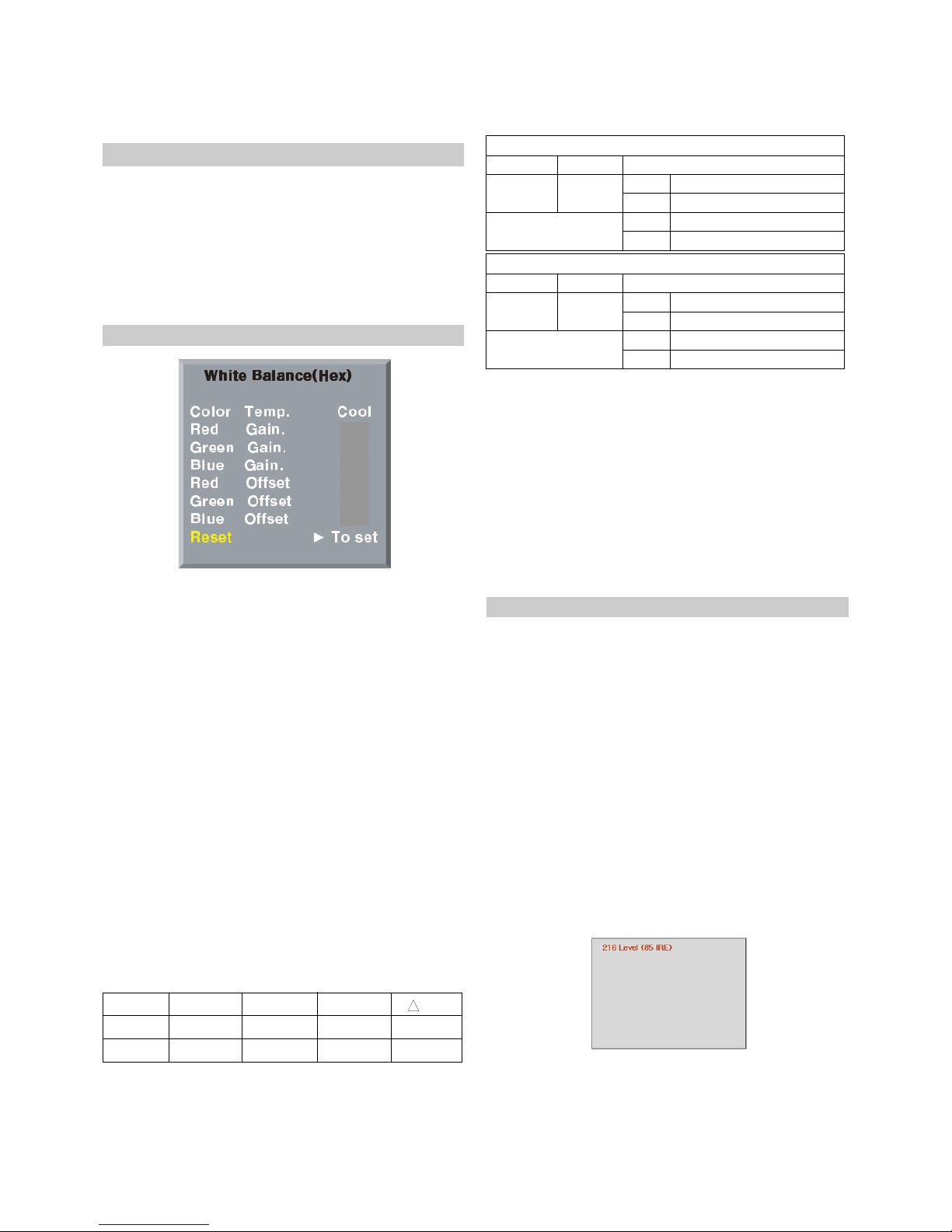
11. hite Balance
* Notice
- Do the white balance adjustment under the 10LUX
- Be ore white balance, press the In-start key 2times and do
the reset like Fig.6
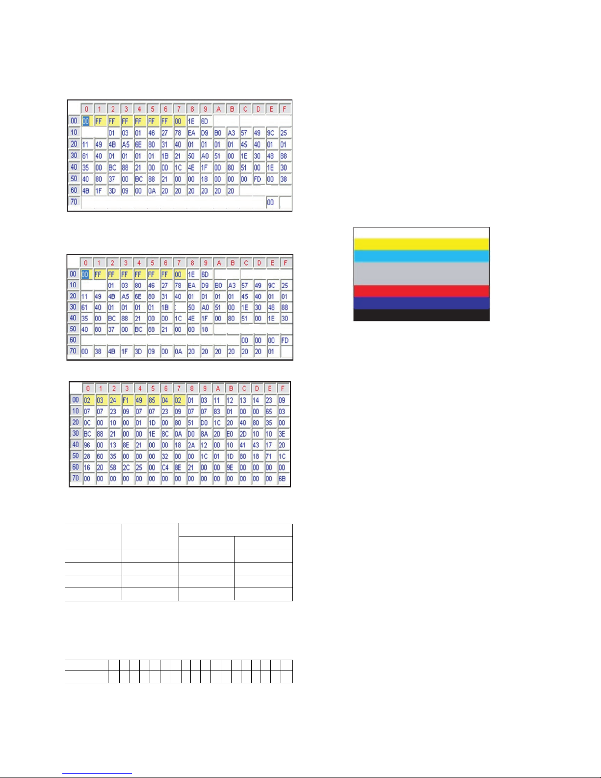
- Use the Torino inner pattern(216 gray pattern)
- To enter White-balance mode,press the IN-START key
2times.
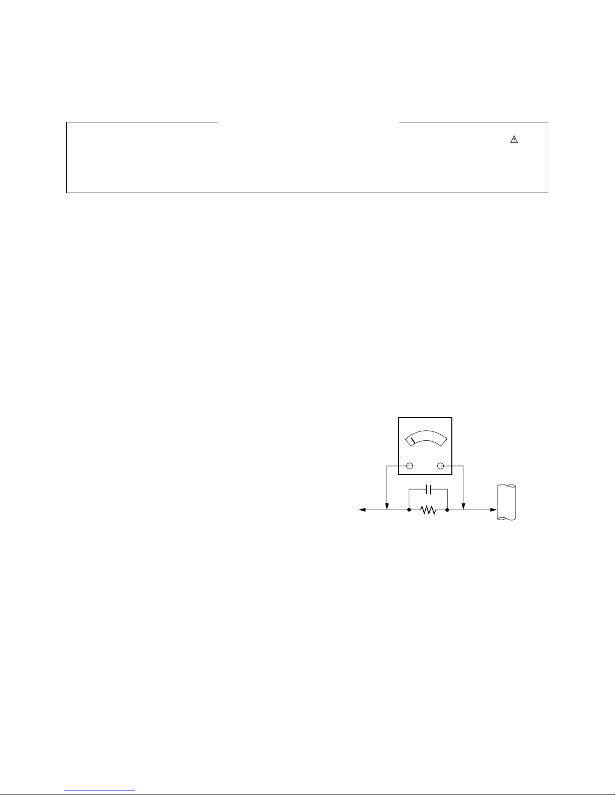
11-1. Test Equipment
(1) Color Analyzer (CA-100),CA-210.
* Note : hen using the Color Analyzer with PDP,
recommend the CA-100 more than CA-210.
If CA-100 can not available, it is also good th use
the CA-210
(2) PC( or communication through RS-232C)
-> UART Baud rate : 115200.
(3) Pattern Generator(MSPG-925FA etc.)
11-2. Color Temperature & Color
Coordinates Setting
(1) When adjusting the Color Temperature o PDP, Color
Analyzer CA-210(Matrix should be corrected through
CH10 o CS-1000) should be used. When CA-210 have
used, it don’t need to it the CH10.
(2) Adjust the Color Temperature based below adjustment
color coordinates.
(3) Even i CH9 o CA-210 is corrected with Matrix, there may
be many character o Module and Filter.
(4) There ore Re er to the below Color Coordinates Target.
But, in case o WCG module, use the CH12 o CA-210.
W Target Value CA-210(CH10), CA-100
( R/G/B gain and R/G/B o set De ault values are di erent in
according to using module)
W
Target Value o Brightness, Color Coordinates, Color Temperature
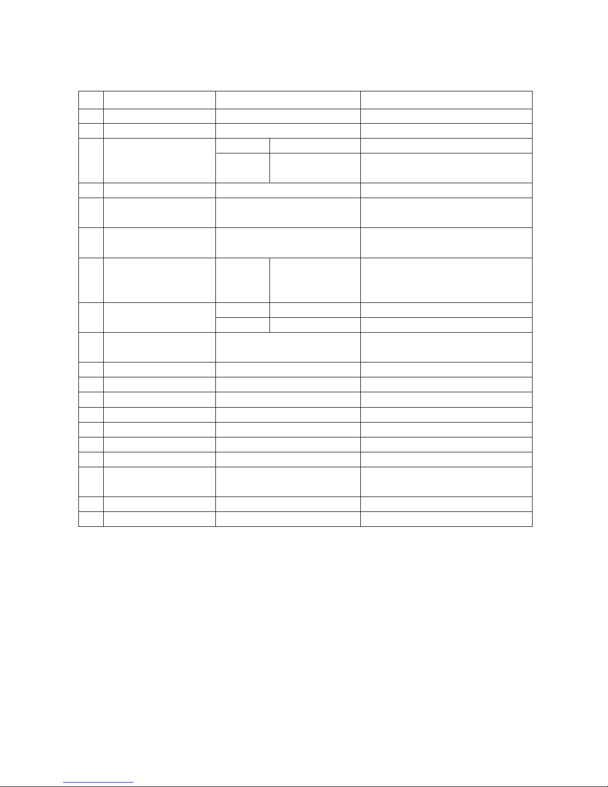
11-3 .Manual white Balance (INNER Pattern)
(For White Balance, Adjust twice, Cool and Warm)
(1)
Execute CA-100, CA-210(10CH) or CA-100 Zero Calibration.
(2) Use torino inner pattern as below Fig.7, Supply 216Level
(85 IRE) ull screen pattern
(3) Enter the White Balance adjustment mode by pressing the
INSTART key twice(White Balance) on R/C.
(4) Stick sensor to center o the screen and select each items
(Red/Green/Blue Gain and O set) using D/E (CH+/-) key
on R/C.
(5) Adjust with R / G / B Gain using F/G(VOL+/-) key on R/C.
(6) Adjust it until color coordination becomes as below.
W Color Temperature : Cool, Medium, Warm
(1) One o R/G.B Gain should be ixed at 80 and adjust two
Gain Value with decreasing the De ault values rom 80
1) When R Gain is Fixed at De ault value(80)
- Adjust G gain and B gain with decreasing De ault values
rom 80
2) When B Gain is Fixed at De ault value(80)
- Adjust R gain and G gain with decreasing De ault values
rom 80
3) When G Gain is Fixed at De ault value(80)
- Adjust R gain and B gain with decreasing De ault values
rom 80
(2) R/G/B Gain and R/G/B O set De ault Value.
- Red Gain : 80
- Green Gain : 80
- Blue Gain : 80
(Fig.6)
- Be ore White-balance, the AV ADC should be done.
- System control RS-232 Host should be “PC“ or adjustment.
- A ter All adjustment is completed, Please push “Instop” Key.
Temp x
0.276±0.002
0.313±0.002
0.283±0.002
0.329±0.002
+0.000
+0.003
11,000K
6,500K
COOL
WARM
CSM y uv
High Light
High Light
60 ± 20cd/m2(42XGA)
Cool X: 0.276±0.002, Y: 0.283±0.002
Normal X: 0.313±0.002, Y: 0.329±0.002
Cool 11,000±500K
Warm 6,500K±500K
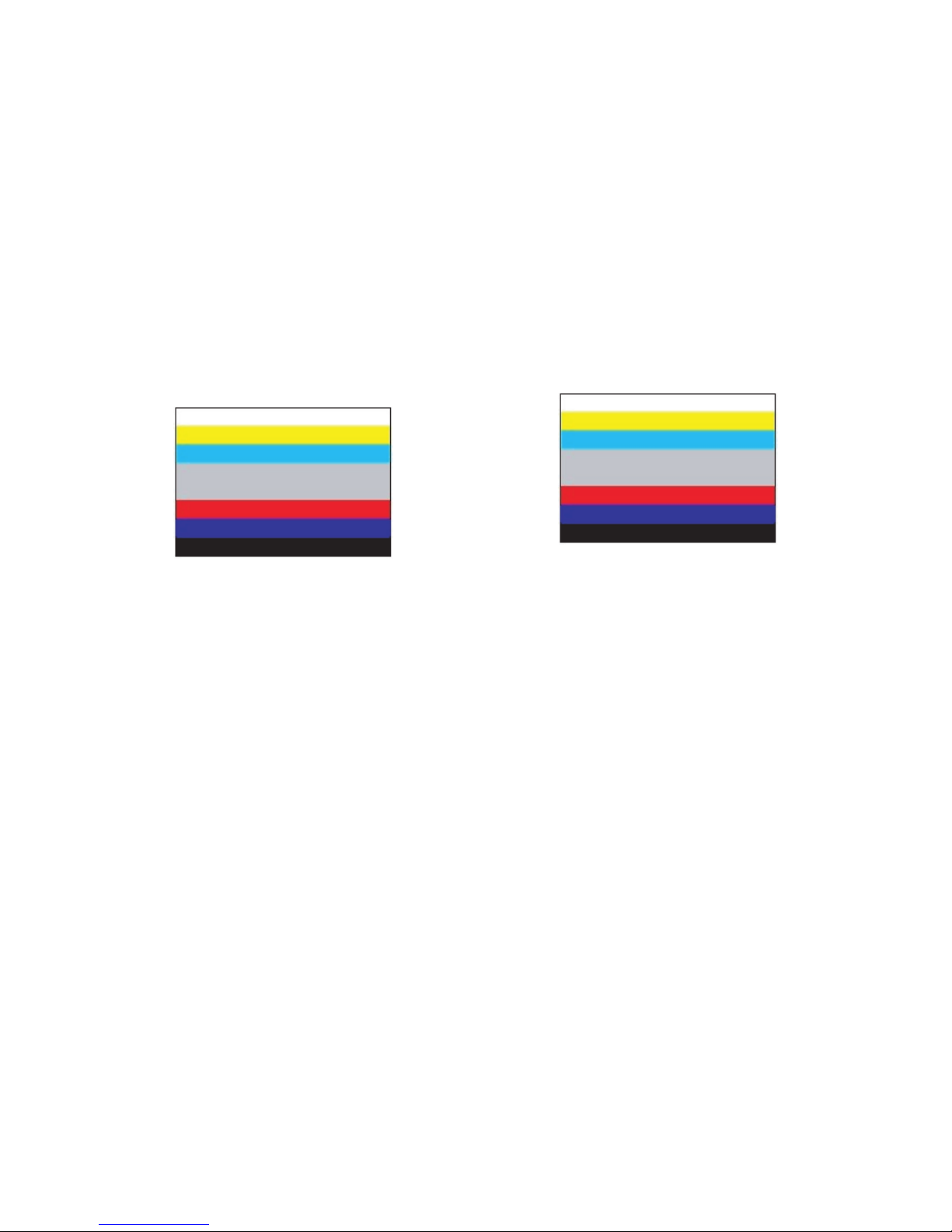
Brightness
Color
-Coordinate
Desired result (216 Gray)
(Fig.7)
Color Temperature
High Light
High Light
50 ± 20cd/m2(80% o non-high altitude)
Cool X: 0.276±0.002, Y: 0.283±0.002
Normal X: 0.313±0.002, Y: 0.329±0.002
Cool 11,000±500K
Warm 6,500K±500K
Brightness
Color
-Coordinate
Desired result or high altitude(216 Gray)
Color Temperature