LG 50PX2DC - - 50" Plasma TV User manual

PLASMATV
carefully and completely before
reference,
number of the TV in the
cover and retate this
uire service,

Waming/Caudon
i;
i0 n
f
WARNING/CAU_ON
WARNING/CAUTION:
TO REDUCE THE RISK OF ELECTRIC SHOCK DO NOT REMOVE COVER (OR BACK) NO USER
SERVICEABLE PARTS INS_DE_ REFER TO QUALIFIED SERWCE PERSONNEL.
The lighthing f_ash with arrowhead symbot, within _ equilateral triangle, is intended to alert the user to
the presence of uninsulated 'dangerous voltage" w_hin the product's enclosure that may be of suffi _
cient m_gnitude to constitute a risk of e_ectdc shock to persons
The exclamagon point within an equilateral triangle is intended to alert the user to the presence of
important operating and maintenance (servicing) instructions in the l_erature accompanying the appli o
ance,
WARNING/CAUTION:
TO PREVENT FIRE OR SHOCK HAZARDS, DO NOT EXPOSE THiS PRODUCT TO RAiN OR MOISTURE.
FCC NOTICE
AClass B digital device
This equipment has been tested and found to comply with the limits for a Class B digital device_ pursuant to Part
15 of the FCC Rules. These timits are designed to provide re_onabte protection against" harmful interference in
a residential installation. This equipment generates, uses and can radiate radio frequency energy and, if not
installed and used in accordance with the instructions, may cause harmfu_ interference to radio communications
However, there is no guarantee that interference will not occur in a pe_cuiar installation if this equipment does
cause harmful interference to radio or television reception, which can be determined by turning the equipment off
and on, the user is encouraged to try to correct the interference by one or more of the foIQowing measures:
- Reorient or relocate the receiving antenna
lncre_e the separation _tween the equipment and receiver
-Connect the equipment into an out_et on a circuit different from that to which the receiver is connected.
-Consult the dealer or an experienced radioFrV technician for help
• Any changes or modifications not expressly approved by the party responsible for compli-
ance could void the user's authority to operate the equipment.
Do not attempt to modify this product in any way without written authorization from LG Electroni_. Unauthorized mod _
fficatbn could void the user's authority to operate this product.
COMPLIANCE:
The responsible pe_ for this produ_s compli_ce is:
LG E_e_ronics U.S.A., thc
100,0 SyJvan Avenue, Englewood Cl_s, NJ 07632
1-800-243_
http://www, lgusa,com
WARNI NG/CAUTION
TO REDUCE THE RISK OF FiRE AND ELECTRIC SHOCK, DO NOT EXPOSE THIS PRODUCT TO
RAIN OR MOISTURE.
J
2 Plasma TV

SafetyInstructions
F
In mons
IMPORTANT SAFETY INSTRUCTIONS
Important safety instructions shal_ _ provided with each apparatus. This information shah be given in a separate booklet or
sheet or be _ocated _fore any operating instructions in an instruction for installation for use and supplied with the appara-
tus. This information shall be given in a language acceptable to the country where the apparatus is intended to be used. The
important safety instructions shatl be entitled 'Important Safety instructions', The fo]iowing safety instructions shah be inctud-
ed where applicable, and, when used shall be verbatim as foltows, Additional safety information may be included by adding
statements after the end of the following safety instruction list At the manufacturer's option, a picture or drawing that illus-
trates the intent of a specific safety instru_on may be placed immediately adjacent to th_ safety instruc_on :
1. Read these instructions.
2. Keep these instructions.
3. Heed all warnings.
4. Follow a|| instrucfions.
5. DO not use this apparatus near water.
6. Clean only with dry cloth.
7. Do not b|ock any ventilation openings. Insta|| in accordance with the manufacturer's instructions.
8. DO not install near any heat sources such as radiators, heat registers, stoves, or other apparatus (including ampli-
fiers)that produce heat.
9= Do not defeat the safety purpose of the _larized or grounding4ype plug. A polarized plug has two b|ades with
one wider than the other. A grounding type plug has two blades and a third grounding prong, The wide b|ade or the
third prong are provided for your safety. If the provided plug does not fit into your outlet, consult an electrician for
replacement of the obsolete outlet,
10. Protect the power cord from being walked on or pinched particularly at plugs, convenience receptacles, and the
point where they exit from the apparatus,
11. Only use aftachn*,-_ntstaccessories specified by the manufacturer.
12. Use only with the cart, stand, tripod, bracket, or table specified by the manufacturer, or sold with the apparatus.
When a cart is used, use caution when moving the caWapparafus combination to avoid injury from tip-over.
PO_[[ABLE CA_T WARNING
Operating Guide 3

Safetytnstructions
13, Unplug this apparatus during lightning storms or when unused for long periods of time.
14. Refer all servicing to qualified service _rsonnel. Servicing is required when the apparatus has been damaged
in any way, such as power_supply cord or plug is damaged, liquid has been spilled or objects have fallen into
the apparatus, the apparatus has exposed to _in or moisture, d_s not operate normally, or has been dropped.
15. CAUTION concerning the Power Cord :
Most appliances recommend they be placed upon a dedicated circuit; that
is, a sfngle outlet circuit which powers only that appliance and has no
additional outlets or branch circuits. Ch_k the specification poge of
this owner's manual to be certain.
Do not overload wall outlets, Overloaded wail outlets, loose or dam_ed
wall outlets, extension cords, frayed power cords, or damged or
cracked wire insulation are dangerous. Any of then conditions could
result in electric shock or ffre_ Perfodtcalry examine the oord of your
appliance, and ff its appearance indicates damage or deterioration,
unplug it, discontinue use of the app|Jance, and have the cord repJaced
with art exact replacement port by an authorized servicer.
Protect the power cord from physical or mechanical abuse, such as being
twisted, kinked, pinched, closed in adoor, or walked upon. Pay
particular attention to plugs, wail outlets, and the point where the
cord exits the appliance.
16, Outdoor Use Marking :
WARNING -To Reduce The Risk Of Fke Or Electric Shock, Do Not Expose This Appliance To Rain Or Moisture.
17. Wet Lo_tion Marking :
Apparatus shall not be exposed to dripping or splashing and no objects _led with Hqutds, such as vans, shall
be placed on the apparatus.
4 Plasma TV

Contenls
Warning/Caution ................................ 2
Saf eby Instructions ............................. 3~4
Introduction
Controis .............................. 7
Connection Options .................. 8
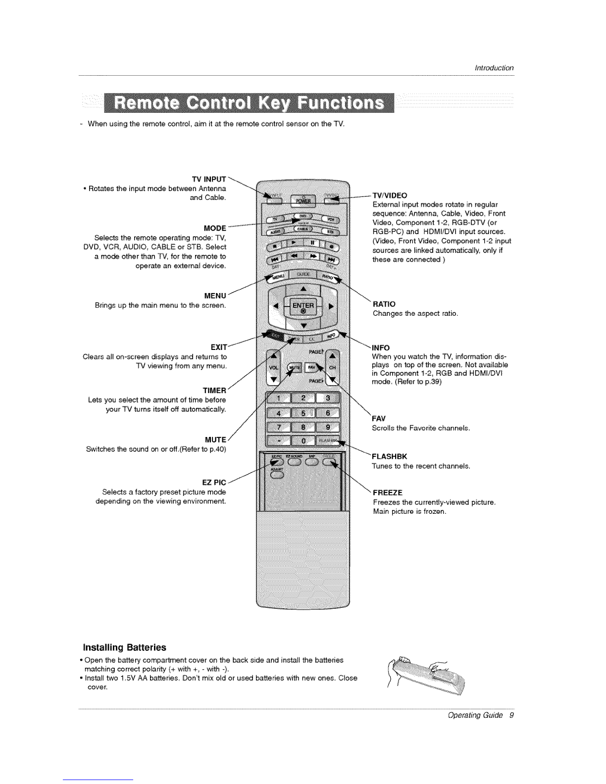
Remote Control Key Functions ............ 9-10
Installation
Accessories ............................ 11
InctaHation instructions .................. 11 ~12
_ning tf_ TV _y to _e _i to protect t_ set
External Equiprr_nt Connections .......... 13~18
Antenna or Cable Connection ........... 13-14
VCR Setup ........................... 14
External A_# Source Setup ................ 15
DVD Setup ......................... 15
HDSTB Setup ......................... 16
PC Setup .............................. 17
Monitor Out Setup ....................... 18
Digita_ Audio Output ...................... 18
HDMI ................................... 19_21
Operation
Turning the TV On ........................ 22
On-screen Menus Language Selection .......... 22
Setup Menu Options
EZ Scan (Channel Search) ............. 23
Manual Ran .......................... 23
Channel Edit ........................... 24
DTV Signal Stren_ ..................... 24
ChanneU _bem Setup .................... 25
Input Source .......................... 25
Input _bei ............................ 25
Video Menu Options
EZ Picture ........................... 26
Manual Picture Control (Custom Option) .... 26
Cotor Temperature Contro_ ............... 26
Video Reset ......................... 26
Audio Menu Options
Audio _nguage ........................ 27
EZ SoundR_e /EZ Sound ................ 27
Manual Sound Control (Custom Option} ...... 27
Front Surround ........................ 28
TV Speakers On!Off Setup ................. 28
BBE ................................. 29
Stereo/SAP Broad_sts Setup ............... 29
Time Menu Options
Auto Ctock Setup ....................... 30
Manual Clock Setup .................... 30
On/Off Timer Setup .................... 30
Sleep Timer/Auto Off .................... 31
Option Menu Features
Aspect Ratio Control .................. 32
Cinema 3:2 Mode Setup ................ 32
Caption ............................. 33
Caption /Text .......................... 33
Caption Option ........................ 34
ISM MeScal ............................. 34
Low Power ............................ 35
Lock Menu Options
Parental Lock Setup ..................... 37
EPG (E_ectronic Program Guide) ............. 38
Brief Info ........................... 39
Mute ................................. 40
Freeze ................................. 40
Screen Setup for PC mode .................... 41
External Control Device Setup ................ 42_-47
IR _es ................................... 48~49
Programming the Remote ...................... 50
Programming Codes ....................... 51 _52
Troubleshooting Ch_kUst ...................... 53
Maintenance ................................. 54
Product Specifications ......................... 55
Warranty ................................... 59~60
Setup and Operation Checklist
Setup and Operation Checkli_
(See pages 13-,21 for available connection and operational setup options.}
1, Unpack TV and a_t accessories, 5 Turn video source equipment on,
2. Connect all extema_ video and audio equipment.
see pages 13_18. 6. _]ect viewing source for TV.
See pages 25,
3 instalt batteries in remote control
See page 9
4. Turn TV on.
See page 22.
7 Fine4une source image and sound to your _rsonal prefer _
ence or as required by source,
See pages 26~ 29.
8, Additiona_ features set up
See Contents above,
After reading this manual, keep it handy for future reference,
Operating Guide 5

Introduction
What is aPlasma Display Panel (PDP)?
Aplasma display panel is the latest display technology and the best way to achieve flat panel displays with excellent image quality
and large screen sizes that are easily viewable, The PDP can be thought of as a descen_nt of the neon lamp and it can be also
be viewed as a series of fluorescent lamps.
How does it work?
PDP is an array of sells, known as pixels, which are comprised of 3sub pixels, corresponding to the cotors red, green, and biue_
Gas in a plasma state is used to react with phosphors in each sub-pixet to produce colored light (red, green, or blue) These phos-
phors are the same types used in Cathode Ray Tube (CRT) devices such as televisions and common computer monitors
You get the rich_ dynamic colors that you expect, Each sub-pixet is individuat_y controlled by advanced erect:tonics to produce over
16 million different colors, Afi of these mean that you get #effect images that are easily viewable in a dispiay that is tess than 5
inches thick,
160 _ - Wide angle range of vision
Your flat paneEplasma screen offers an exceptionally broad viewing angme_-over 160 degrees. This means that the dis#fay is
clear and visibte to viewers anywhere in the room who can see the screen.
Wide Screen
The screen of the Plasma Display is so wide that your viewing experience is as ff you are in a theater.
Multimedia
Connect your piasma display to a PC and you can use it for conferencing, games, and tntemet browsing_
Versatile
The iight weight and thin size makes it easy to install your plasma display in a vanety of locations where conventional TVs will not
fit,
The PDP Manufacturing ProceSS: a few minute colored dots may be print on the PDP Screen
The PDP (Plasma Display Panel), which is the display device of this product, is composed of 0.9 to 2.2 mi[Uion ceils. A few ce_
defects wil_ normally occur in the PDP manufacturing process. _veral tiny, minute colored dots visible on the screen shoufd be
acceptable. This _so occurs in other PDP manufacturers' produds. The tiny dots appearing does not mean that this PDP is defec -
_ve. Thus a few cell defects are not sufficient cause for the PDP to be exchanged or retemed. Our production technology mini-
mizes these se_l defects during the manufacture and operation of this product.
6 Plasma TV

Introduction
-This is asimplified representation of front pane].
Here shown may be somewhat different from your TV.
Front Panel Controls
2 3 45
i, POWER Button
2. Remote Control Sensor
3. Power Standby Indicator
4, TV/VtDEO Button
5. MENU Button
6, ENTER Button
7. VOLUME (_1, I_) Buttons
8, CHANNEL (Y, A) Buttons
Operating Guide 7

Introdue#on
Back Connection Panel
S-VIDEO Input
VIDEO Input
Connects the video signal from a
video device.
AUDIO Input
Use to connect to hear stereo sound
from an extema_ device.
RS-232C INPUT (CON- Audio/Video input Monitor
TROLiSERVICE) PORT Connect audio/video _tput
Connect to the RS_ output from an Connect a
232C port on a PC. external device to second TV or
these jacks,
S-Vid_ Input
Connect S-Video out
from an S-VIDEO
device to the S-
VIDEO input
DVDiDTV Input
(Cogent 1-2)
Connect a com_nent
video/audio device to
RGBiDVI
AUOIO
INPLrr
In RGB input
or DVl input,
th,;s port sup-
plies Analc_
audio.
HDMIiOVI Digital Audio Output
(VlOEO)INPUT Connect digital audio
connect a from various types of
DVl(Video) sig- equipment.
hal to HDM_iDVL Note: tn standby
mode,
this port will not work,
Antenna Input RGB INPUT Power Cord Socket
Connect over-the_ Connect the monitor Thi;s TV operates on
an AC pewe_. The
air s{gnais to this output connector Remote volte_ is indicated on
iack, from a PC to the Control Port the Specifications
CABLE Input appropriate input Conned your page, Never attempt
Connect came sig- port, wired remote to operate the TV on
nals to this _aek. c_ntrot here. DC power.
8 Plasma TV

Introduction
-When using the remote control, aim it at the remote control sensor on the TV,
TV
• Reties the inp_ mode between Antenna
_d Cable.
Selects the remote operating mode: TV,
DVD, VCR, AUDtO, CABLE or STB, Select
a mode other than TV, for the remote to
operate an external device
Brings up the main menu to the screen.
Ctears all on-screen displays and returns to
TV viewing from any menu,
Lets you select the amount of time before
your _¢ turns itseff off automatically,
Switches the sound on or off.(Refer to p40)
EZ PIC J
Selects a factory preset picture mode
depending on the viewing environment.
Externa{ input modes rotate in regular
sequence: Antenna, Cable, Video, Front
Video, Component 1-2, RGB-DTV (or
RGB-PC) and HDMIiDW input sources.
(Video, Front Vide, Component 1-2 input
sources are _inked automati_3_y, on_y ff
these are connected )
Changes the asset ratio.
When you watch the TV, information dis-
plays on top of the screen. Not available
in Component 1-2, RG8 and HDMI/DVI
mode, (Refer to p39)
Scrolls the Favorffe channels,
Tunes to the recent channels,
"\"" FR E_ E
Freezes the currently-viewed picture,
Main picture is frozen.
Installing Bakeries
* Open the battery compartment cover on the back side and instai! the batteries
matching correct polarity (+ w_th +, =with -)
.[nstalt two 1 5V AA batteries Don"t mix old or used batteries with new ones. Close
cove K
Operating Guide 9

introduction
Turns your TV or any other programmed
equipment on ot off, depending on mode,
_UMBS"rlCK
AUIows you to navigate the on*screen menus
and adjust the system settings to your pref=
erenc_,
Select a ciosed caption:
Off, CC1 ~4, Text1 ~4,
Increases/decreases the sound JeveL
Selects the sound appropri_e for the pro_
gram's character,,
ADJ
Adjusts screen position, size_ and phase in
PC mode,
VCRiDVD BUTTONS
Control some video cassette recorders
or DVD p_ayers. ("'RECORD" b_ton is not
available for DVD p_ayers.)
U|DE
Shows program schedule.
CHANNEL UPtDOWN
Setests available channels found with EZ
scan,
PAGE UP/PAGE DOWN
Moves from one full set of screen infor-
mation to the next one,,
SAP
_tects MTS sound: Mono_ Stereo_ and
SAP in Analog mode. Change the audio
langua_ in DTV m_e.
10 P_a TV

Installation
Ensure that the following accessories are included with your pFasma display, If an a_essory is miming, please contact the _er
where you purchased the product.
Operating Guide Batteries Power Cord 75_ Round Cable
Remote Contro_ 2-Wall brackets 2-eye -bo_ts D-sub 15 pin Cable (RGB)
* Secure the TV assembEy by joining it to a wail by using the TV!Wat[ brackets,
_ i
'.............................
, If the set will be mounted on a _sk top, insert
the 2 eye-bolts and tighten them securely in the upper
holes as shown
hstall the wall brackets on the wall with 2 bo_s*, (not
supplied with the product), as shown.
Match the height of the eye-bolts and the walt brack-
ets_
Check to be sure the eye-boBts and the brackets are
tightened securely.
/,
J
• Secure the _ assembly to the wa_l with strong strings
or wire cables, (not supplied with the product), as
shown,
Operating Guide 11

/nstalta#on
The TV" can be [ns_led in various ways such _ on a wall, or on a desktop etc,
• The TV is designed to be mounted horizontally,
GROUNDING
Ensure that you connect the earth ground wire to prevent possible
e_ectric shock If grounding methods are not possible, have a quaiified
electrician inst_J a separate circuit breaker, Do not try to ground the
unit by connecting it to telephone wires, lightening rods, or gas pipes.
For proper ventilation, aiiow a clearance of 4" on
each side and the top, 2._' on the bottom, and
2" from the wall Detai_ed installation instructions
are includ_ in the optional Desktop Stand
_nstai[aflon.
To Install on a Oesktop
Pede_ta[_ mount minimum
a_towaMec_eatances for adequate ven_iation.
12 P_a TV

Installation
1, Analog and Digital TV signals provided on antenna
- Wall Antenna Socket or Outdoor Antenna without a CaMe Box Connections
For optimum picture quality, adjust antenna direction if needed.
Mufti-family Dwellings/Apartments
antenna socket)
VHF Antenna
UHF Antenna
Bronze Wke
Outer
Antenna
f
Turn d_kwise to tkjhten. °.................
Bronze Wire
Single-family Dwellings/Houses
(Connect to walE jack for outdoor antenna)
Be careful not to bend the bronze wire when
connecting the antenna.
J
,.i'
2, Analog and Digital TV signals provided on cable
CaMe TV Wail Bronze Wire
BroPuze Wire
Operating Guide 13

Installation
3, Analog and Digital TV signals provided on cable and antenna
/f Antenna Bronze Wire
Cable TV Wall Turn clockwise to tighten.
Jack RF Coaxia_ Wire (75 ohm)
Bronze Wire
• To improve the pict_Jre quality in a poor signa_ area,
please purchase a sign_ _plifier and install properly.
•If the antenna needs to be split for two TV's, install a '_-
Way Signa_ Splitte¢' in the connections.
• If the antenna is not installed proper_y, cart#act your deal-
er for assistance.
i j
- To avoid picture noise (interference), leave an adequate distance between the VCR and "P.7
- Use the ISM Method (on the Option menu) feature to avoid having a fix_ image remain on the screen for a _eng period ef time
If the 4:3 picture format is used; the fixed images on the sides of the screen may remain visible en the screen
Connection Option 1
Set VCR eutput swish to channel 3 or 4 and
then tune the TV to the same channel number
Connection Option 2
1, Connect the audio and video cables from the
VCRs output jacks to the TV input jacks_ as
shown in the figure,
When connecting the TV to VCR, match the
jack colors (Vi_o = yellow, Audio Left = white,
and Audio Right = red),
If you connect an S-WDEO output from VCR to
the S-V_DEO input, the picture quality is
improved; compared to connecting a regular
VCR to the Video input
2, Unsert a video tape into the VCR and press
PLAY on the VCR_ (Refer to the VCR owner's
manual )
&Seiect the inp_ source with using the
_/VIDEO bu_on on the remote control, Note
that this TV finds the connected input sources
automatically for Video, Front Video and
Component 1-2. It is presumed that RGB and
HDMI/DW sources are connected,
De not connect to both Vi_o and
S_Video at the same time,
[]
VCR Rear
14 P_a TV

tnstallation
How to connect
Connect the audio and video cables from the e×ternaJ equip-
ment's output jacks to the TV input jacks, as shown in the
figure.
When connecting the TV to external equipment, mutch the
jack colors (Video = yellow, Audio Left = whffe, and Audio
Right = red).
How to use
1. Select the input source with using the TW_.,/IDEO button on
the remote contro4. Note that this TV finds the connected
input sources automaticafly for Video, Front Video and
Component 1-2 it is presumed that RGB and HDMIiDVI
sources are connected.
2. Operate the corresponding external equipment.
Camcorder
Video Game
Device
DVD
How to connect
1. Connect the DVD video outputs (Y, PB, PR) to the COMPONENT (Y, P& PR) iNPUT jacks on the TV and connect the DVD
audio outputs to the AUDIO INPUT jacks on the TV, as shown in the figure
2. If your DVD on_y has an S-Video output jack, connect this to the SWIDEO input on the TV and connect the DVD audio outputs
to the AUDIO INPUT jacks on the TV, as shown in the figure.
Note: If your DVD player does not have component video output, use SoVideo.
How to u_
1_ "rum on the DVD player, insert a DVD
2. Use the _iVIOEO button on the remote control to seUect Component 1 or Component 2 (If connected to S-VIDEO, select
the Video or Front Video external input source,)
3 Refer to the DVD ptayer's manuat for operating instructions,
" Component input ports
To get better picture quality, conn_ a DVD pUayer to the com_-
nent input ports as shown below:
Component ports
on the TV
Video output ports
on DVD player
Operating Guide 15

/nstaltabon
¸
- This TV can receive Digital Over4he-aidCab[e signals without an external digital set4op box. However, if you _ receive Digital
signals from a dig_ta_ set4op box or other digital externa_ device, refer to the figure as shown below.
This TV supports HDCP (HJgh-bandwio_h Digital Contents Prot_tion) protocol for Digital Contents (480p 720p i080i).
Or
or
Digital Set4op Box:
HOW to COllrleCt
Use the TV's COMPONENT (Y, P& PR) iNPUT, RGB or HDMJ/DW _ack
for video connections depending on your set4op box connector Then,
make _e corresponding audio connections.
How to use
1. Turn on the digital set4op box. (Refer to the owner's _nua[ for the
digital set4op box.)
2. Use TViVIDEO on the remote cor_tro[ to _lect Component 1,
Com_nent 2, RGB-DTV, or HDM|iDVl source.
S!gnal Component 1/2 RGB-D_, HDMP'DV[
480i Yes No
480p Yes Yes
72#p Yes . Yes
1080i Yes Yes
16 P_a TV

installation
This TV provides Plug and Play capability, meaning that the PC adjusts autom_tica{Iy to the TVs settinge_
= The TV perceives 640x480, 60Hz as DTV 480p based on the PC graphic card, ch_qge the screen scanning rate for the graphic
card accordingly:
<When the PC supports DVI>
How to connect
1. Connect the PC to HDMIiDVt port of this TV with an HDMI-to-DVt c_ble(not supplied with this product).
2. ff the PC(or the sound card of the PC) has an anaiog audio output connector, connect the PC"s audio output to RGB/DVl
AUDIO INPUT po_ located or_ the upper side of RGB INPUT port.
How To Use
1. To get the best picture quality, adjust the PC graphics _rd to 1024x7_, 60Hz.
2. Select HDMIiDVI input source in input source option of SETUP menu.(Refer to P.25)
TV/VIDEO button is also avaii_le for this purpose.
3. Check the image on your TV'. There may be noise associated with the resolution, vertica_ pattern, contrast or brightness in PC
mode. ff noise is present, change the PC output to another resolution, change the refresh rate to another rate or adjust the
brightness and contrast on the VIDEO menu unti_ the picture is clear, if the refresh rate of the PC graphic card can not be
changed, change the PC graphic card or consult the manufacturer of the PC graphic card.
<When the PC supports RGB>
How to connect
1 Connect the PC to RGB INPUT port of this TV with a RGB cable(not supplied with this product),
2 If the PC(or the sound card of the PC) has an analog audio output connector, connect the PC's audio output to RGB/DVI
AUDIO INPUT pert located on the upper side of RGB LNPUT port
How To Use
1 To get the best picture quality, adjust the PC graphics card to 1024x768_ 60 Hz
2 Select RGB-PC input source in input source option of SETUP m_nu (Refer to P,25)
Once you select RGB-PC in mare input option of SETUP menu, TViVIDEO button is aiso available for this purpose,
3, Check the image on your -DZ There may be noise associ_ed with the resolution, ver_ca[ pattem, contrast or brightness in PC
mode_ ff noise is present change the PC output to another resolution, change the refresh rate to another rate or adjust the
brightness and contrast on the VIDEO menu until the picture is dear_ ff the refresh rate of the PC graphic card can not be
changed, change the PC graphic card or consult the manufacturer of the PC graphic card,
Monitor Display Specifications (RGB-PC)
Hortzo ntal Vertical Horizo ntal Vertical
Resolution Frequency(KHz) Frequency(Hz) Resolution Frequency(KHz) Frequency(Hz)
640x350 31.469 70.08
31,469 59.94
640x480 37,861 72,80
37.500 75.00
720x4_ 31.469 70.08
800x600
1024x768
35.156
37.879
4&077
4&875
48.363
56,476
60_023
56.25
60.31
72,18
7&00
60_00
70,06
75.02
Operating Guide 17

Installation
Monitor Display Specifications (HDMI/DVI Mode)
Hortzon_l Vertical Horizontal Vertical
Resolution Frequency(KHz) Frequency(Hz) Resolution Ft_uency(KHz) Frequency(Hz)
640x480
800x600
31,469
37,861
37.500
35.156
37.879
48.077
46,875
5'&94
72_80
75,00
56.25
60,31
72,18
7&O0
1024x768
48,363
56,476
60,023
60,00
70_06
7&02
The TV has a sped_ signa[outputcapabili_ which allows you
hook up a second TV or monito£
Connect the second TV or monitor to the TV's MONITOR OUTPUT.
See the Operating Manuai of the second TV or monitor for further
detaims regarding that devices input settings.
Notes:
*Component, RGB-PC/RGB-DTV, HDMI/DVI_ DTV input sources
cannot be used for Monitor out.
.When connecting with external audio equipments, such as amplif-
ere or speakets, please turn the TV speakers elL(Refer to p,28)
*We t;_commend to use the _ideo andaudio output jacks for VCR
recording,
Second TV or rr_niter
Send the TV's audio to e_ema] audio equ{pment (stereo system) via
the Digital Audio Output (Optical) _rt,
How to connect
1 Connect one end of an optical cable to the FV Digita_ Audio
(Optical) Output po_
2 Connect the other end of the optical cable to the digital audio (opti-
c[) input on the audio equipmenL
See the external audio equipment instruction manual for operation_
Note: When connecting with external audio equipment& such as
amplifers or speaker& pteas_ turn the TV speakers off4"Refer to
p28)
Caution: Do not look into the optical output port.
Looking at the [_er _am may damage
your vision.
External Audio Equipment
18 P_a TV

tnstallation
HIGH _NR-k3N MULTIMED_ INTEF{F,_3E
-HDMI TM, the HDMI logo and High-Definition Multimedia interface is a ttade_rk or registered trademark of HDM_ Licensing."
This TV can receive the High-Definition Multimedia _nterface(HDMI) or the Digita} Visua_ tnterface(DVI).
-This TV supports HDCP(High-bandwidth Dig_al Contents Protection) Protocol for 720x480p, 1280x720p, and 1920x1080i resolu-
tion.
-When you connect this TV w_h a source device(DVD player, Set Top Box or PC) supporting Auto HDMIiDVI function, the output
resolution of the source device will be automatically set to 1280x720p.
-If the source de,vice does not support Auto HDM_iDW, you need to set the output resolution appropriately.
To get the best picture quality; adjust the DVD Player or Set Top Box's output resolL_ion to 12_x720p, and the PC graphics cerd's
o_put resolution to 1024x768, 60Hz.
off the source device has an HDMI output, no other audio connection is necessary _use HDMIoto-HDMI connection includes
both video and audio.
-If the source device has a DVI output and no HDMI output, a separated aud{o connection is necessa_,
<When the source device(DVD player or _t Top Box) supports HDMI>
How To Connect
1. Connect the source device to HDMI/DV_ port of this TV with an HDM_ cable(not supplied with this product).
2. No _parated audio connection is necessary:
How To Use
oif the source device supports Auto HDMI function, the output resolution of the source device wil_ be automa_ca]ly set to 1280x720p,
if the source device does net support Auto HDML you need to set the output resolution appropriately,
To get the best picture quality, adiust the output resolution of the source device to 1280x720p
Select HDMI/DVl input source in input source option of SETUP menu(Refer to P,25)
TV/VIDEO b_on is aEso available for this purpose
<When the source device(DVD player or Set Top Box) suppers DVI>
How To Connect
1, Connect the source device to HDMt/DV_ port of this TV with a HDMFto_DVl cebte(not supplied with this product),
2_ A _parated audio connection is necessary
& If the source device has an analog audio output connector, connect the PC's audio output to RGB/DV} AUDIO INPUT port leoat -
ed on the upper side of RG8 INPUT port
How To U_
If the source device supports Auto DVI function, the ou_ut resolution of the source device wiB be automatically set to 1280x720p.
- if the source device does not support Auto DVI you need to set the outp_ resolution appropriately:
To get the best picture quality, adiust the output resolution of the source device to 1280x720p.
o Select HDMI/DVl input source in input source option of SETUP menu.(Refer to P.25)
TViVIDEO button is also avail_le for this purpose.
Operating Guide 19

installation
Cable sample
/
HDMI Cable
(not supplied with the product)
HDMI to DVI Cable
(not supplied with the product)
Fiber Optic Digital Audio Cable
(not supplied with the product)
Analog Audio Cable(RCA type)
(not supplied with the product)
Analog Audio Cable(Stereo to RCA type)
(not supplied with the product)
%*_..... . .....J
20 P_a TV
Other manuals for 50PX2DC - - 50" Plasma TV
1
This manual suits for next models
1
Table of contents
Other LG Plasma TV manuals
Popular Plasma TV manuals by other brands

Samsung
Samsung PL42E7SX/RCL Service manual

Palsonic
Palsonic PDP4212HD instruction manual

Panasonic
Panasonic Viera TH-42PX74EA operating instructions

DAEWOO ELECTRONICS
DAEWOO ELECTRONICS DPP-42A1GCSB Service manual

Panasonic
Panasonic Viera TH-37PD60E operating instructions

Palsonic
Palsonic PDP4275 owner's manual