LG LRE30755SW User manual

30” Freestanding Electric Range
SERVICE MANUAL
MODEL: LRE30755SW / SB / ST
CAUTION
BEFORE SERVICING THE UNIT, READ THE SAFETY PRECAUTIONS IN THIS MANUAL.
Website http://us.lgservice.com
P/NO : 3828W5S6293
December, 2005
Printed in Korea

This LG Service Manual, “ 30” Freestanding Self-Cleaning Electric Range,” provides the
technician with information on the operation and service of the Freestanding Self-Cleaning
Electric Range. It is to be used as a training Service Manual. For specific information on the
model being serviced, refer to the “Owner’s Manual” or “Tech Sheet” provided with the electric
range.
SAFETY PRECAUTIONS
• Repairs of the appliance should be carried out by a licensed technician only. Incorrect repairs
may result in dangerous situations. If you need repairs, contact an LG Service Center or your
dealer.
• If the power cord is defective, it must be replaced by a qualified service agent with a UL listed
range cord.
• Electrical leads and cables should not be allowed to touch the oven.
• Rating plate is located on the left side of warming drawer.
• The power supply of the appliance should be turned off when it is being repaired.
FORWARD
LG Electronices assumes no responsibility for any repairs made
on our products by anyone other than Authorized Service Technicians.
WARNING
•
To avoid risk of severe personal injury or death, disconnect power before working/servicing on
appliance to avoid electrical shock.
•
When the oven operates, the interior parts will be very hot.
!

(P
AGE
)
GENERAL
--------------------------------------------------------------------------------------------
1-1 ~ 1-4
• Important safety instructions
--------------------------------------------------------------------------------------
1-1 ~ 1-2
• Model & Serial number label and tech sheet locations
-----------------------------------------------------------
1-3
• Specifications
------------------------------------------------------------------------------------------------------------------
1-4
USING YOUR RANGE
-------------------------------------------------------------------------
2-1 ~ 2-5
• General imformation
---------------------------------------------------------------------------------------------------------
2-1
• Control panel features
----------------------------------------------------------------------------------------------
2-2 ~ 2-5
- To turn on a single surface unit (Right Rear, Left Rear, Left Front)
- To turn on a dual surface unit (Right Front)
- To set the warming zone controlTo set the warming zone control
- Setting the Clock
- Start, Clean/Off and On/Off pad
- To turn On/Off the oven light
- Timer On/Off
- Options pad: 6 categories
1) Convection auto conversion
2) Thermostat adjustment
3) Language selection (English or Spanish )
4) Preheating alarm light On/Off
5) Beeper volume
6) Temperature unit (°F or °C)
-
Bake, Timed Bake, Delayed timed Bake
- Broil
- Convection Bake
- Convection Roast
- Favorites
- Cook & Warm
- Oven lockout
- Changing hour mode on clock (12HR, 24HR)
- Proof
- Self-Clean
- Warming drawer
COMPONENT ACCESS
---------------------------------------------------------------------
3-1 ~ 3-17
• Component Locations
------------------------------------------------------------------------------------------------------
3-1
• Removing the Back, Control cover and Key membrane Assembly
-------------------------------------------
3-2
• Removeing the Control Power Supply and Power Control Board (PCB)
-----------------------------------
3-3
• Removing the Surface Element and the Ceramic Glass Cooktop
-------------------------------------------
3-4
• Removing the Door Latch and the Door Switch
---------------------------------------------------------------------
3-5
• Removing the BROIL element
-------------------------------------------------------------------------------------------
3-6
• Removing the BAKE element
---------------------------------------------------------------------------------------------
3-7
• Removing the CONVECTION element, Fan blade and Fan motor
-------------------------------------------
3-8
• Removing the Oven light & Socket assembly
-----------------------------------------------------------------------
3-9
• Removing the latch drive assembly
-----------------------------------------------------------------------------------
3-10
- Door locking mechanism
----------------------------------------------------------------------------------------------
3-10
• Removing the Oven temperature Sensor
---------------------------------------------------------------------------
3-11
• Removing the Warming drawer element & temperature sensor
----------------------------------------------
3-12
• Removing & Replacing the Lift-off Oven Door
---------------------------------------------------------------------
3-13
• Removing the Oven Door Handle & Glass
----------------------------------------------------------------
3-14 ~ 3-15
• Removing the Oven Door Gasket
-------------------------------------------------------------------------------------
3-16
• Removing a Side Panel
---------------------------------------------------------------------------------------------------
3-17
TABLE OF CONTENTS

(Page)
COMPONENT TEST
-----------------------------------------------------------------------------
4-1 ~ 4-8
•
Convection Motor
-----------------------------------------------------------------------------------------------------------
4-1
•
Door locking Motor
---------------------------------------------------------------------------------------------------------
4-2
•
Micro Switch (normally open type)
-----------------------------------------------------------------------------------
4-2
•
LVT
-------------------------------------------------------------------------------------------------------------------------------
4-2
•
Oven Sensor
-----------------------------------------------------------------------------------------------------------------
4-3
•
Warming Drawer Sensor
------------------------------------------------------------------------------------------------
4-3
•
Door switch
-------------------------------------------------------------------------------------------------------------------
4-3
•
Broil element
-----------------------------------------------------------------------------------------------------------------
4-4
•
Bake element
----------------------------------------------------------------------------------------------------------------
4-4
•
Convection element
-------------------------------------------------------------------------------------------------------
4-4
•
Warming Drawer element
-----------------------------------------------------------------------------------------------
4-4
•
Oven lamp
--------------------------------------------------------------------------------------------------------------------
4-5
•
Single surface unit(LF, LR, RR)
--------------------------------------------------------------------------------------
4-6
•
Warming Zone
--------------------------------------------------------------------------------------------------------------
4-7
•
Dual surface unit(RF)
-----------------------------------------------------------------------------------------------------
4-8
COMPOSITION OF CONTROL
-------------------------------------------------------------
5-1 ~ 5-4
• Main PCB
-----------------------------------------------------------------------------------------------------------------------
5-2
• Cook-top display PCB
------------------------------------------------------------------------------------------------------
5-3
• Cook-top relay PCB
---------------------------------------------------------------------------------------------------------
5-4
• Oven relay PCB
---------------------------------------------------------------------------------------------------------------
5-4
FAILURE MODE FLOW CHART
------------------------------------------------------------
6-1 ~ 6-11
•
No display (No power)
--------------------------------------------------------------------------------------------
6-1 ~ 6-4
•
Oven does not heat
-----------------------------------------------------------------------------------------------
6-5 ~ 6-7
•
Cook-top does not heat
------------------------------------------------------------------------------------------
6-8 ~ 6-9
•
Oven lamp does not operate
-----------------------------------------------------------------------------------------
6-10
•
No key input
----------------------------------------------------------------------------------------------------------------
6-11
FAILURE CODES
------------------------------------------------------------------------------------------
7-0
F-CODE FLOW CHART
---------------------------------------------------------------------
7-1 ~ 7-10
•
F-1 error
------------------------------------------------------------------------------------------------------------------------
7-1
•
F-2 error
---------------------------------------------------------------------------------------------------------------
7-2 ~ 7-4
•
F-3, F-4 error
---------------------------------------------------------------------------------------------------------
7-5 ~ 7-6
•
F-5, F-6 error
---------------------------------------------------------------------------------------------------------
7-7 ~ 7-8
•
F-9 error
-------------------------------------------------------------------------------------------------------------
7-9 ~ 7-10
APPENDIX A (SCHEMATIC DIAGRAM OF PCB)
--------------------------------------------
8-1
TROUBLE SHOOTING
-------------------------------------------------------------------------
9-1 ~ 9-3
SCHEMATIC DIAGRAM
--------------------------------------------------------------------------------
10-1
• STRIP CIRCUITS
-------------------------------------------------------------------------------------------------
10-2 ~ 10-6
EXPLODED VIEW
----------------------------------------------------------------------------
11-1 ~ 11-8

• Be sure your appliance is properly installed and grounded by a
qualified technician.
• Do not repair or replace any part of the appliance unless
specifically recommended in the manual.
All other servicing should be referred to a qualified technician.
• Always disconnect power to appliance before servicing by
removing the fuse or switching off the circuit breaker
To reduce the risk of tipping of the range, the range must be
secured by properly installed anti-tip devices. To check if the
bracket is installed properly,
- Warming drawer : grasp the top rear edge of the Range and
carefully attempt to tilt it forward.
verify that the anti-tip devices are engaged.
- Storage drawer : Remove drawer and verify leveling leg is
inserted into and fully secured by the anti-tip devices.
Refer to the installation manual for proper anti-tip bracket
installation.
• Do not step, lean or sit on the doors of the range -this can cause
the range to tip, resulting in burns or serious injuries.
• Do Not Leave Children Alone - Children should not be left alone or
unattended in area where appliance is in use. They should never be
allowed to sit or stand on any part of the appliance.
• Never Use Your Appliance for Warming or Heating the Room.
• Storage in or on Appliance – Flammable materials should not be stored
in an oven or near surface units. Be sure all packing materials are removed
from the appliance before operating it. Keep plastics, clothes and paper
away from parts of the appliance that may become hot
• Wear Proper Apparel – Loose-fitting or hanging garments should never
be worn while using the appliance.
• Do Not Use Water on Grease Fires – Turn off oven to avoid spreading
the flame. Smother the fire or flame by closing the door or use dry
chemical, baking soda or foam- type extinguisher.
• Use Only Dry Potholders – Moist or damp potholders on hot surfaces
may result in burns from steam.
Do not let potholder touch hot heating elements. Do not use a towel or
other bulky cloth.
1-1
GENERAL
IMPOR
IMPORT
TANT SAFETY INSTRUCTIONS
ANT SAFETY INSTRUCTIONS
Read and follow all instructions before using your oven to prevent the risk of fire, electric shock, injury to person, or
damage when using the range. This guide don’t cover all possible conditions that may occur. For further assistance
contact your service agent or manufacturer.
This symbol will help alert you to hazards or unsafe practices which could cause serious
bodily harm or death.
!
WARNING
Do not store items of interest to children in cabinets
above a range or on the back guard of a range – children
climbing on the range to reach items could be seriously
injured.
WARNING
• DO NOT TOUCH HEATING ELEMENTS OR INTERIOR
SURFACES OF OVEN – Heating elements may be hot even
though they are dark in color. Interior surfaces of an oven
become hot enough to cause burns. During and after use, do
not touch, or let clothing or other flammable materials contact
heating elements or interior surfaces of oven until they have
had sufficient time to cool. Other surfaces of the appliance may
become hot enough to cause burns – among these surfaces
are oven vent openings and surfaces near these openings,
oven doors, and windows of oven doors.
WARNING
SURFACES
• DO NOT TOUCH SURFACE UNITS OR AREAS NEAR UNITS –
Surface units may be hot even though they are dark in color. Areas
near surface units may become hot enough to cause burns. During
and after use, do not touch, or let clothing or other flammable
materials contact surface units or areas near units until they have
had sufficient time to cool. Among these areas are the cook-top and
surfaces close to the cook-top.
WARNING
To avoid risk of electrical shock, personal injury, or death,
make sure your range has been properly grounded and
always disconnect it from main power supply before any
servicing.
– INJURIES CAN OCCUR IF THE
RANGE TIPS
– INSTALL ANTI-TIP DEVICE
PACKED WITH RANGE
– FOLLOW ALL INSTALLATION
INSTRUCTIONS
!
WARNING
!
CAUTION
!
!
!

1-2
GENERAL
SURFACE COOKING UNITS
• Use Proper Pan Size – This appliance is equipped with one or
more surface units of different sizes. Select utensils having flat
bottoms large enough to cover the surface unit heating element.
The use of undersized utensils will expose a portion of the heating
element to direct contact and may result in ignition of clothing.
Proper relationship of utensil to burner will also improve efficiency.
• Never Leave Surface Units Unattended at High Heat Settings
– Boil overs may cause smoking and greasy spillovers may ignite.
• Make Sure Reflector Pans or Drip Bowls Are in Place –
Absence of these pans or bowls during cooking may subject
wiring or components underneath to damage.
• Protective Liners – Do not use aluminum foil to line surface unit
drip bowls or oven bottoms, except as suggested in the manual.
Improper installation of these liners may result in a risk of electric
shock, or fire.
• Glazed Cooking Utensils – Only certain types of glass,
glass/ceramic, ceramic, earthenware, or other glazed utensils are
suitable for range-top service without breaking due to the sudden
change in temperature.
• Utensil Handles Should Be Turned Inward and Not Extend
Over Adjacent Surface Units – To reduce the risk of burns,
ignition of flammable materials, and spillage due to unintentional
contact with the utensil, the handle of a utensil should be
positioned so that it is turned inward, and does not extend over
adjacent surface units.
• Do Not Soak Removable Heating Elements – Heating
elements should never be immersed in water.
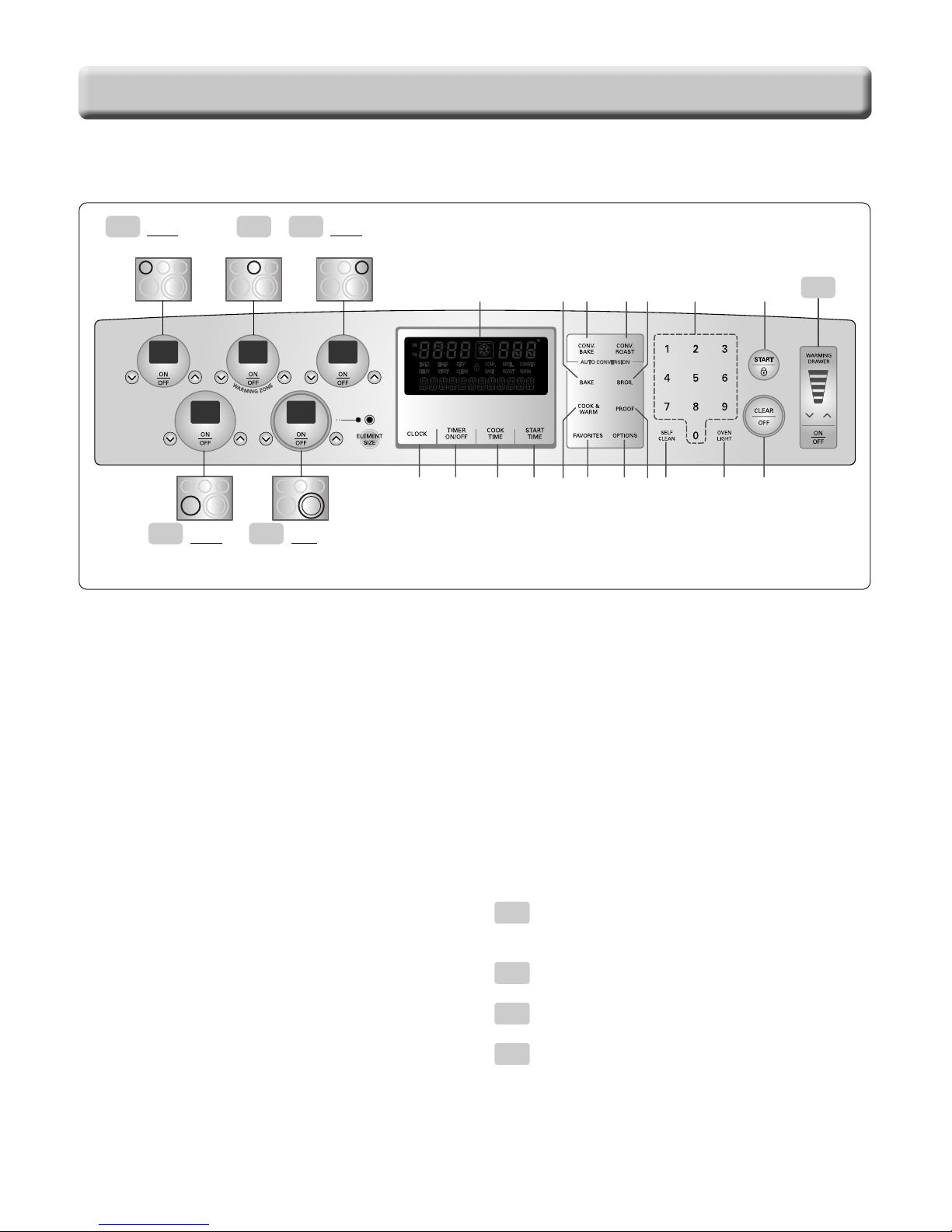
• Be sure you know which control pads operate each surface unit.
Make sure you turned on the correct surface unit.
SELF-CLEAN OVENS
• Do Not Clean Door Gasket – The door gasket is essential for a
good seal. Care should be taken not to rub, damage, or move the
gasket.
• Do Not Use Oven Cleaners – No commercial oven cleaner or
oven liner protective coating of any kind should be used in or
around any part of the oven.
• Clean in the self-clean cycle only parts listed in this manual.
Before self-cleaning the oven, remove the broiler pan and any
utensils from the oven.
• Never keep pet birds in the kitchen – the health of birds is
extremely sensitive to the fumes released during an oven self-
clean cycle. Fumes may be harmful or fatal to birds. Move birds to
well-ventilated room.
• Important Instruction – In the event the self-clean mode “F”
code goes on, or three long beeps sound, oven is malfunctioning
in the self-clean mode. Turn off or disconnect appliance from
power supply and have serviced by a qualified technician.
IMPOR
IMPORT
TANT SAFETY INSTRUCTIONS
ANT SAFETY INSTRUCTIONS
VENTILATING HOODS:
• Clean Ventilating Hoods Frequently – Grease should not
be allowed to accumulate on hood or filter.
• When flaming foods under the hood, turn the fan on.
OVEN
• Use Care When Opening Door – Let hot air or steam escape
before you remove or replace food in the oven
• Do Not Heat Unopened Food Containers – Build-up of pressure
may cause container to burst and result in injury.
• Keep Oven Vent Ducts Unobstructed – the oven vent is located
above the left rear surface unit. this area could become hot during
oven use. Never block this vent and never place plastic or heat-
sensitive items on vent
• Placement of Oven Racks – Always place oven racks in desired
location while oven is cool. If rack must be moved while oven is
hot, do not let potholder contact hot heating element in oven.
• Do Not allow aluminum foil or meat probe to contact heating
elements.
GLASS/CERAMIC COOKING SURFACES
• Do Not Cook on Broken Cook-Top – If cook-top should break,
cleaning solutions and spillovers may penetrate the broken cook-
top and create a risk of electric shock. Contact a qualified
technician immediately.
• Clean Cook-Top With Caution – If a wet sponge or cloth is used
to wipe spills on a hot cooking area, be careful to avoid steam
burn. Some cleaners can produce noxious fumes if applied to a hot
surface.
DEEP FAT FRYERS:
• Use extreme caution when moving the grease kettle or disposing
of hot grease.

1-3
GENERAL
The Model/Serial Number label and Tech Sheet locations are shown below.
Model & Serial
Number Location
MODEL & SERIAL NUMBER LABEL
AND TECH SHEET LOCA
AND TECH SHEET LOCATIONS
TIONS
Tech Sheet Location
(On Low Rear Cover)

1-4
GENERAL
SPECIFICA
SPECIFICATIONS
TIONS
Model Number LRE30755SW / SB / ST
Category Convection
Overall
Control
Cooktop
Power
Oven
Drawer
Dimensions
(inch)
Power
Width
Installation type
Color availability
Oven
Cooktop
Display
Electronic clock & timer
Control lock capability
Audible preheat signal
Special function
Material
# of element
LR
RR
CR
LF
RF
Capacity(cu.ft)
Broil element
Bake element
Convection System
-Convection element
# of Racks
Interior oven light
Proof
Cook & warm
Favorites
Door lockout
Broiler pan
Type
Element
Warming rack
Oven Interior(W x H x D)
Exterior - Width
Exterior - Height
Exterior - Depth
Net weight: Lbs (Kg)
Rating
30"
Freestanding
WH, BK, STS
Keypad
Keypad
Scroll VFD
Yes
Yes
Yes
Option(6 categories)
1. Convection auto conversion 0n/0ff
2. Thermostat Adjustment
3. Language -English or Spanish
4. Preheating alarm light On/Off
5. Beeper Volume
(loud, normal, low, mute)
6. Temperature unit (F / C)
Ceramic glass
5
6"-1,200
6"-1,200
warming zone
9"-2,500
Dual (9”/12"-1,700/2,700)
5.6
4000 watts
3400 watts
Yes
Yes (800w, 120v)
3 (2 standard, 1 Split)
120V, 40Watts
Yes
Yes
Yes
1. Bread 2. Meat 3. Chicken
Yes
Yes
Warming drawer
600 watts
Yes
24 1/2x 20 1/4x 19 3/8
29 7/8
36 (cooktop), 47 5/8 (backguard top)
25 11/16 (Door), 28 (with handle)
181 lbs (82kg)
12.7Kw(120/240V) / 9.7Kw(120/208V)

2-1
USING YOUR RANGE
Rating Label
Model numbers are recorded on the rating label.
Rating label is located on the lower front left corner
of the oven frame. It can be seen by opening the
storage drawer or warming drawer. Before ordering
parts, write down the correct model and serial
number from rating label. This avoids incorrect
shipments and delays. Please refer to parts
reference material when ordering replacement parts.
Functional Operation
Bake Mode
Top and hidden bottom elements operate during
bake. Bake can be used to cook foods which are
normally baked. Oven must be preheated.
Broil Mode
Top element operates during broil. Broil can be
used to cook foods which are normally broiled.
Preheating is not required when using broil. All
foods should be turned at least once except fish,
which does not need to be turned.
Convection Bake / Roast Mode
Upper element, lower element, Rear element(some
model) and fan operate during convection bake.
Convection bake should be used for cooking
casseroles and roasting meats. Oven should be
preheated for best results when using convection
bake. Pans do not need to be staggered. Cooks
approximately 25% quicker than bake.
Cooking Guide
Refer to the owners manual for recommendations
of times and temperatures. Times, rack position,
and temperatures may vary depending on
conditions and food type. For best results, always
check food at minimum time. When roasting,
choose rack position based on size of food item.
GENERAL INFORMA
GENERAL INFORMATION
TION
Broil element
Hidden bake
element
Broil element
Convection
element
Hidden bake
element
Broil element
Hidden bake
element

2-2
USING YOUR RANGE
CONTROL P
CONTROL PANEL FEA
ANEL FEATURES
TURES
1. BAKE PAD: Press to select the bake function.
2. BROIL PAD: Press to select the broil function.
3. CONVECTION BAKE PAD: Press to select baking
with the convection function.
4. CONVECTION ROAST PAD: Press to select
roasting with the convection function.
5. NUMBER PADS: Use to set any function requiring
numbers such as the time of day on the clock, the
timer, the oven temperature, the start time and
length of operation for timed baking.
6. START PAD: Must be pressed to start any cooking
or cleaning function.
7. CLEAR/OFF PAD: Press to cancel all oven
operations except the clock and timer.
8. CLOCK PAD: Press before setting the time of day.
9. TIMER ON/OFF PAD: Press to select the timer
feature.
10. COOK TIME PAD: Press and then use the number
pads to set the amount of time you want your food
to cook. The oven will shut off when the cooking
time has run out.
11. START TIME PAD: Use along with BAKE, CONV.
BAKE, CONV. ROAST, COOK TIME and SELF
CLEAN pads to set the oven to start and stop
automatically at a time you set.
12. COOK & WARM PAD: Press to keep cooked
foods warm. See page 2-4 for pad operation.
13. FAVORITES PAD: Press to set favorite cooking.
14. OPTIONS PAD: Press to set 6 types of option
category.
15. PROOF PAD: Press to select a warm environment
useful for rising yeast-leavened products.
16. SELF CLEAN PAD: Press to select self-cleaning
function. See page 2-4 for pad operation.
17. OVEN LIGHT PAD: Press to turn the oven light on
or off.
18. DISPLAY
Single surface unit
: Right Rear, Left Rear, Left Front
Dual surface unit : Right Front
Warming Zone : Center Rear
Warming Drawer
8
18 1 3 4 2 5 6
910111213141516 177
single
Left Rear element
single
Left Front element
Dual
Right Front
Dual element
Warming zone
single
Right Rear element
D
A A
A B
C
A
B
C
D

2-3
USING YOUR RANGE
To turn on a single surface unit
(Right Rear, Left Rear, Left Front)
1. Press ON/OFF pad for the desired element.
2. Press ( / ) pad to choose the desired setting.
To turn on a dual surface unit
(Right Front)
1. Press ON/OFF pad
2. Press the ELEMENT SIZE pad as needed to
select the desired burner size. When first
selected, 9” size is on. The light above the
ELEMENT SIZE pad indicates which size
surface unit is on.
2. Press ( / ) pad to choose the desired setting.
Note:
• Each time a pad is pressed a beep will sound.
• The power level decreases or increases by 0.5
from 9.0 through 3.0. (by 0.2 from 3.0 through 1.0)
• Lo is the lowest power level available.
• “HS” will appear when the unit is hot to touch
To set the warming zone control
1. Press ON/OFF pad at the warming zone.
2. Press ( / ) pad to choose the desired setting.
Note:
• Each time a pad is pressed a beep will sound.
• The controls for the warming zone allow for 5
different heat settings : Lo~Hi
• “HS” will appear when the unit is hot to touch.
1. SETTING THE CLOCK
2. START, CLEAN/OFF AND ON/OFF PAD
1. Touch START pad to start oven.
2. Touch CLEAR/OFF pad to cancel a program
during cooking or Erase during programming.
3. Touch ON/OFF pad to start or cancel the
surface unit.
3. TO TURN ON/OFF THE OVEN LIGHT
The oven light automatically turns ON when the
door is opened. The oven light may also be
manually turned ON or OFF by pressing the
OVEN LIGHT pad
Note: The oven light cannot be turned on if self-clean feature
is active.
4. TIMER ON/OFF
To cancel timer at any time, touch TIMER ON/OFF pad.
Note:
1. If you press TIMER ON/OFF pad once, this allows you to
select "seconds"
(for example: if you press “5” and “6”, it means 56 seconds)
2. If you press TIMER ON/OFF pad twice, this allows you to
select "minutes"
(for example: if you press “5” and “6”, it means 56 minutes)
5. OPTIONS PAD: 6 types of category
1) CONVECTION AUTO CONVERSION
1. Press OPTIONS pad once
2. Press “1”pad for ENABLE
or “2”pad for DISABLE
3. Press START pad.
2) THERMOSTAT ADJUSTMENT
The oven temperature can be adjusted from
-35°F (-19°C) to 35°F (19°C).
Note: The thermostat adjustments made with this feature will
just change Bake, Convection Bake and Convection
Roast temperature.
To increase the oven temperature:
1. Press OPTIONS pad twice
2. Press the desired temperature
3. Press START pad.
To decrease the oven temperature:
1. Press OPTIONS pad twice
2. Press the desired temperature
3. Press the OPTIONS pad once
4. Press START pad
3) LANGUAGE SELECTION (English or
French)
1. Press OPTIONS pad 3 times
2. Press “1”pad for ENGLISH
or “2”pad for FRENCH
3. Press START pad
4) PREHEATING ALARM LIGHT ON/OFF
1. Press OPTIONS pad 4 times
2. Press “1”pad for ON
or “2”pad for OFF
3. Press START pad
CLEAR
/OFF CLOCK Desired
Time START
TIMER
ON/OFF
Desired
time
TIMER
ON/OFF
A
B
C

5) BEEPER VOLUME
1. Press OPTIONS pad 5 times
2. Press “1”pad for loud level,
“2”pad for normal level,
“3”pad for low level,
“4”pad for mute level,
3. Press START pad
6) TEMPERATURE UNIT (°F or °C)
1. Press OPTIONS pad 6 times
2. Press “1”pad for °F
or “2”pad for °C
3. Press START pad
6. BAKE, TIMED BAKE, DELAYED TIMED BAKE
7. BROIL
8. CONVECTION BAKE
9. CONVECTION ROAST
10. FAVORITES
11. COOK & WARM
12. OVEN LOCKOUT
13. CHANGING HOUR MODE ON CLOCK
(12HR, 24HR)
14. PROOF
15. SELF-CLEAN
2-4
USING YOUR RANGE
CONV.
BAKE
Desired
Temp. START
CONV.
ROAST
Desired
Temp. START
START
FAVORITES
: Once →Bread
: Twice →Meat
: 3 times →Chicken
START
SELF CLEAN
: Once →3-hour
: Twice →2-hour
: 3 times →4-hour
START
COOK &
WARM
Press and hold the START pad for 3 seconds
(to activate or reactivate LOCKOUT)
START
PROOF
Press and hold the START pad for 3 seconds
Press “1”pad for 12-hour,
“2”pad for 24-hour. START
START
TIME
Desired
start time START
BAKE Desired
temperature START
COOK
TIME Desired time START
START
TIME
Desired
start time START
START
BROIL: once →Hi
: twice →Low

2-5
USING YOUR RANGE
The rack can be used in 2 ways:
• In the upright position to allow low profile food
items to be placed both under and on top of the
rack (for example, rolls or biscuits on top of the
rack and a casserole dish underneath).
• In the downward position to allow you to place
light weight food items and empty cookware (for
example, rolls or pastries and dinner plates)on the
rack. Set the Warming Drawer rack in either
position as shown below (Fig.1).
To Operate the Warming Drawer
The purpose of the Warming Drawer is
to keep hot cooked foods at serving
temperature. Always start with hot food.
It is not recommended to heat cold food
in the Warming Drawer.
All food placed in the Warming Drawer
should be covered with a lid or
aluminum foil to maintain quality. Do
not use plastic wrap to cover food.
Plastic may melt onto the drawer and be
very difficult to clean. Use only utensils
and cookware recommended for oven
use in the Warming Drawer.
To set the warming drawer control
1. Press the ON/OFF pad at the
WARMING DRAWER
position. The indicator light
will flash.
(If no further pads are
pressed within 25 seconds,
the display will clear.)
2. Press ( ) once to turn on
the power level for high(5
level) or ( ) for Low(1 level).
3. Use the ( )/( ) pad to
choose the desired power
setting.
(Adjustable at any time while
the Drawer is ON.)
4. When the food is ready for
removal, press the ON/OFF
pad once to turn off.
Note: The Warming Drawer will shut off
automatically after 3 hours.
W
WARMING DRA
ARMING DRAWER
WER
Warming Drawer Rack
in upward position
Warming Drawer Rack
in downward position
!
CAUTION
Always use pot holders or oven mitts when
removing food from the Warming Drawer as
cookware and plates will be hot and you can be
burned.
Warming
Drawer
Control

3-1
COMPONENT ACCESS
This section instructs you on how to service each component inside the range. The components and their
locations are shown below.
COMPONENT LOCA
COMPONENT LOCATIONS
TIONS
Broil Heater
Oven Sensor
Door Switch
Surface Elements
Door Locking Motor
& Micro Switch
Cook Top
Relay PCB
Main PCB
Cook Top
Display PCB
Bake Heater
Hinge Hanger
Warming Drawer
Heater
Warming Drawer
Sensor
Oven Light
LVT
Convection Heater
Door Latch Assembly
Convection Motor
Oven Relay PCB
Thermal Fuse

3-2
COMPONENT ACCESS
1. Turn off the electrical supply going to the range.
2. Pull the range away from the wall so that you can
access the rear panel.
3. Remove the 16 screws from the rear panel and
remove the panel.
4. Remove the 3 screws from the rear control cover
and remove the cover.
5. Remove 6 screws of PCB assembly and separate
PCB assembly.
6. Remove 9 screws of KEY Membrane assembly and
separate PCB assembly.
REMOVING THE BACK, CONTROL COVER
AND KEY MEMBRANE ASSEMBL
AND KEY MEMBRANE ASSEMBLY
Y
WARNING
ELECTRICAL SHOCK HAZARD
Disconnect power before servicing the range.
Replace all panels before operating range.
Failure to do so can result in death or electrical
shock.
!
!
CAUTION
When you work on the electric range, be careful
when handling the sheet metal parts. Sharp
edges may be present, and you can cut yourself if
you are not careful.
Control Cover
Back Cover
PCB Assembly
KEY MEMBRANE Assembly

3-3
COMPONENT ACCESS
REMOVING THE CONTROL POWER SUPPL
REMOVING THE CONTROL POWER SUPPLY
Y
AND POWER CONTROL BOARD (PCB)
1. Turn off the electrical supply going to the range.
2. Pull the range away from the wall so that you can
access the rear panel.
3. Remove back cover & control cover (See step
3~4 on page 3-2)
4. There are 3 PCB's (power control board). When
you check PCB, check the proper pcb in default
mode and check main pcb.
NOTE: Refer to the page 5-1~5-4 for
composition of control board
5. To remove the control power supply:
a) Disconnect 2 connectors.
b) Remove the two screws.
WARNING
ELECTRICAL SHOCK HAZARD
Disconnect power before servicing the range.
Replace all panels before operating range.
Failure to do so can result in death or electrical
shock.
!
!
CAUTION
When you work on the electric range, be careful
when handling the sheet metal parts. Sharp
edges may be present, and you can cut yourself if
you are not careful.
Cook-top Relay PCB Main PCB
2 Connector
2 Screws
Oven
Relay PCB

CERAMIC GLASS COOKTOP REMOVAL
Step. 1
Unplug the cord or disconnect power
Step. 2
Open oven door and
remove the 3screws located
at the front of the cook-top,
then close the door.
Step. 3
Lift up the cooktop front and
Remove the ground screw
securing ground wire
Step. 4
Slightly lift up and pull up the
cook-top and then unplug
the 2 connectors at the back
by squeezing side tabs
3 Screws
Step. 5
Protect the cooktop surface
and turn the assembly over.
Step. 6
To remove the surface elements
a) Remove the wires from
the element and limiter
terminals.
b) Remove the element
bracket screw (shown
above) for the element
you are servicing.
d) Carefully lift the bottom of the bracket just far enough
to remove the element.
REASSEMBLY NOTE: When you reinstall the element
make sure that the wires are inserted into the correct
tap then reinstall the bracket screw to secure it to the
cooktop.
3-4
COMPONENT ACCESS
REMOVING THE SURF
REMOVING THE SURFACE ELEMENTS
ACE ELEMENTS
AND THE CERAMIC GLASS COOKT
AND THE CERAMIC GLASS COOKTOP
OP
WARNING
ELECTRICAL SHOCK HAZARD
Disconnect power before servicing the range.
Replace all panels before operating range.
Failure to do so can result in death or electrical
shock.
!
Bracket screws
Ground Screws
2 Connectors

3-5
COMPONENT ACCESS
REMOVING THE DOOR LA
REMOVING THE DOOR LATCH & DOOR SWITCH
TCH & DOOR SWITCH
WARNING
ELECTRICAL SHOCK HAZARD
Disconnect power before servicing the range.
Replace all panels before operating range.
Failure to do so can result in death or electrical
shock.
!
1. Turn off the electrical supply going to the range.
2. Open the oven door.
3. Raise the cooktop (see page 3-4 for the
procedure).
4. To remove the door latch:
a) Remove the two screws from the door latch
and remove the latch.
b) Remove the door latch from the burner box
and unhook the actuating rod.
5. To remove the door switch:
a) If not already done, raise the cooktop
(see page 3-4 for the procedure).
b) Remove the door switch from the range.
To do this, squeeze tabs and use a ratchet
extension or a small socket, and tap it out of
the hole with a hammer.
c) Disconnect the wires from the terminals.
!
CAUTION
When you work on the electric range, be careful
when handling the sheet metal parts. Sharp
edges may be present, and you can cut yourself if
you are not careful.
2 Screws
Unhook
Actuating
Rod
Wires
Door
Switch

3-6
COMPONENT ACCESS
REMOVING THE BROIL ELEMENT
WARNING
ELECTRICAL SHOCK HAZARD
Disconnect power before servicing the range.
Replace all panels before operating range.
Failure to do so can result in death or electrical
shock.
!
1. Turn off the electrical supply going to the range.
2. Open the oven door and remove the racks from
inside the oven.
3. To remove the broil element:
a) Remove the 4 screws from the front and rear
brackets.
b) Pull the element forward so that you can
access the terminals and disconnect the wires.
!
CAUTION
When you work on the electric range, be careful
when handling the sheet metal parts. Sharp
edges may be present, and you can cut yourself if
you are not careful.
2 Rear bracket Screws
2 Upper bracket Screws
2
Terminals

1. Unplug range or disconnect power.
2. Pull the range out of its mounting location so that
you can access the rear of the unit.
3. Remove the rear panel from the unit.
(See step 3 on page 3-2 for procedure)
4. Remove the 2 screws of
power cord assembly
box and 1 ground screw.
5. Set the box aside
6. Cut the 9 points of flange and remove the bake
heater cover.
3-7
COMPONENT ACCESS
7. Bend the insulation glass fiber up.
8. Remove two screws
and bend up two flanges
9. Carefully pull the hidden bake element and its
mounting bracket out of the range.
REPLACING THE MOUNTING BRACKET
1. Drive the two screws
REMOVING THE HIDDEN BAKE ELEMENT
Hidden bake element
Hidden bake element
Hidden bake element
Hidden bake element
Hidden bake element
Hidden bake element
Hidden bake element
Hidden bake element
Hidden bake element
Hidden bake element
Hidden bake element
Hidden bake element
Hidden bake element
Hidden bake element
Hidden bake element
Hidden bake element
Hidden bake element
Hidden bake element
Hidden bake element
Hidden bake element
Hidden bake element
Hidden bake element
Hidden bake element
Hidden bake element
Hidden bake element
Hidden bake element
Hidden bake element
Hidden bake element
Hidden bake element
Hidden bake element
Total 9 points
Total 9 points
Total 9 points
Total 9 points
Total 9 points
Total 9 points
Total 9 points
Total 9 points
Total 9 points
Total 9 points
Total 9 points
Total 9 points
Total 9 points
Total 9 points
Total 9 points
Total 9 points
Total 9 points
Total 9 points
Total 9 points
Total 9 points
Total 9 points
Total 9 points
Total 9 points
Total 9 points
Total 9 points
Total 9 points
Total 9 points
Total 9 points
Total 9 points
Total 9 points
Screw
Screw
Screw
Screw
Screw
Screw
Screw
Screw
Screw
Screw
Screw
Screw
Screw
Screw
Screw
Screw
Screw
Screw
Screw
Screw
Screw
Screw
Screw
Screw
Screw
Screw
Screw
Screw
Screw
Screw
Flanges
This manual suits for next models
2
Table of contents
Other LG Range manuals

LG
LG LRG5115 Series User manual

LG
LG LRE30955ST Use and care manual

LG
LG LSE3090ST User manual

LG
LG LDG3031ST User manual

LG
LG LDG3036ST User manual

LG
LG LRE30955ST Use and care manual

LG
LG LRFVS3006S User manual

LG
LG LSRG309ST User manual

LG
LG LRE3027ST Specification sheet

LG
LG LRG30355SB - 30in Gas Range User manual
Popular Range manuals by other brands

Viking
Viking Professional Custom VGSC548-4GQ Specifications

Smeg
Smeg CO68CMP manual

Whirlpool
Whirlpool YWGE745C0FS User instructions

Whirlpool
Whirlpool WDE350LVB02 installation instructions

Maytag
Maytag MGS5875BDW - Slide in Gas Range Use and care guide

Whirlpool
Whirlpool RF301OXTW01 installation instructions