LG LMC25780SB Instruction Manual

P/No. MFL62184503
Please read this guide
thoroughly before
o erating and kee it handy
for reference at all times.
Veuillez lire ce guide attentivement
avant la mise en service de l’a areil
et gardez-le à ortée de main
our le consulter en cas de besoin.
Lea detenidamente estas
instrucciones antes utilizar
el frigorífico y guárdelas como
referencia ara el futuro.
LMC25780**
To contact LG Electronics, 24 hours a day,
7 days a week:
1-800-243-0000
Or visit us on the Web at: us.lge.com
Pour contacter LG Electronics, 24 heures ar
jour, 7 jours ar semaine:
1-800-243-0000
Ou visitez notre site Web à l’adresse: us.lge.com
Para comunicarse con LG Electronics,
24 horas al día, 7 días a la semana:
1-800-243-0000
O visítenos en la Web en: us.lge.com

2
IMPORTANT SAFETY INFORMATION
Basic Safety Precautions ........................................3
CFC Dis osal ..........................................................4
How to Connect Electricity ......................................5
PARTS AND FEATURES
Key Parts and Com onents ....................................6
INSTALLATION
Choose the Pro er Location ..................................7
Clearances .............................................................7
Flooring ...................................................................8
Handle Removal .....................................................8
Door and Drawer Removal .....................................9
Light bulb re lacement .........................................16
Connecting the Water Su ly ..............................17
Connecting the Water Lines .................................18
Leveling the Refrigerator Doors ...........................21
Starting .................................................................22
HOW TO USE
Ensuring ro er air circulation .............................23
Multi-flow ..............................................................23
Setting the controls ..............................................23
Automatic Icemaker .............................................24
Storing Foods .......................................................25
Location of Foods .................................................26
Shelf Height Adjustment .......................................27
CARE AND CLEANING
Removing and Re lacing Com onents ................28
Cleaning the Refrigerator .....................................31
General Information .............................................31
TROUBLESHOOTING
Before Calling for Service …………………………32
SPECIFICATIONS
Key Dimensions and S ecifications .....................35
WARRANTY
Product Registration Information ..........................36
THANK YOU!
Congratulations on your urchase
and welcome to the LG family.
Your new LG French Door
Refrigerator combines
advanced cooling technology
with sim le o eration and high
efficiency. Follow the o erating
and care instructions in this
manual and your refrigerator
will rovide you with many years
of reliable service.

3
BASIC SAFETY PRECAUTIONS
This guide contains many important safety messages. Always read and obey all
safety messages.
w This is the safety alert symbol. It alerts you to safety messages that inform you of hazards that can kill
or hurt you or others or cause damage to the roduct. All safety messages will be receded by the safety
alert symbol and the hazard signal word DANGER, WARNING, or CAUTION. These words mean:
wANGER You might be killed or seriously injured if you don’t follow instructions.
wWARNING You can be killed or seriously injured if you don’t follow instructions.
wCAUTION Indicates an imminently hazardous situation which, if not avoided, may
result in minor or moderate injury, or roduct damage.
All safety messages will identify the hazard, tell you how to reduce the chance of injury, and tell you
what can ha en if the instructions are not followed.
wWARNING
To reduce the risk of fire, electric shock, or
injury to persons when using your product,
basic safety precautions should be followed,
including the following.
Read all instructions before using this appliance.
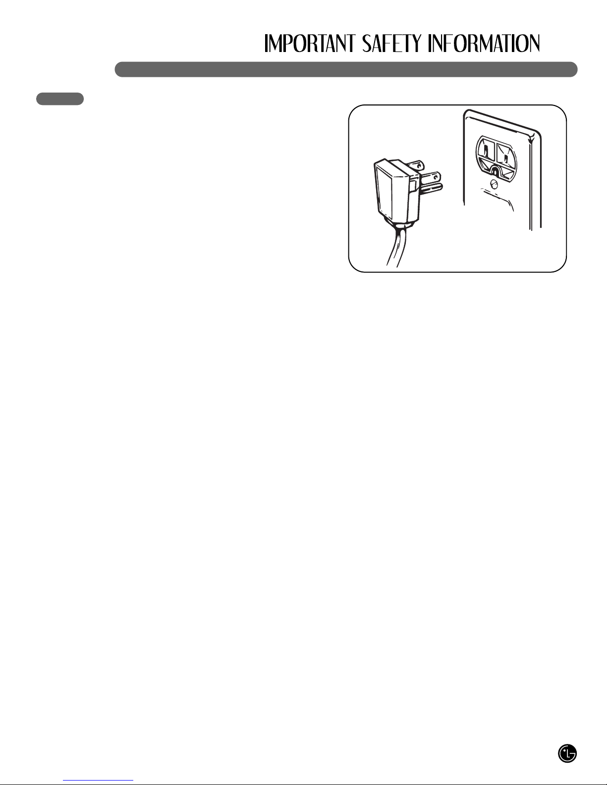
• NEVER un lug your refrigerator by ulling on the
ower cord. Always gri the lug firmly and ull it
straight out from the outlet.
• Re air or re lace immediately all electric service
cords that have become frayed or otherwise
damaged. Do not use a cord that shows cracks or
abrasion damage along its length or at either the
lug or connector end.
• When moving your refrigerator away from the wall,
be careful not to roll over or damage the ower cord.
• DO NOT store or use gasoline or other flammable
va ors and liquids in the vicinity of this or any other
a liance.
• Do NOT allow children to climb, stand, sit or hang
on doors, drawers or shelves of the refrigerator.
They could damage the refrigerator and seriously
injure themselves.
• Kee fingers out of inch oint areas; clearances
between the doors and cabinet are necessarily
small. Be careful closing doors when children are
in the area.
• Un lug your refrigerator before cleaning or making
any re airs.
NOTE: Service should be erformed by a qualified
technician.
• Before re lacing a burned-out light bulb, un lug the
refrigerator or turn off ower at the circuit breaker
or fuse box in order to avoid contact with a live wire
filament. (A burned-out light bulb may break when
being re laced.)
NOTE: Some models have LED interior lighting and
service should be erformed by a qualified
technician.
NOTE: Setting either or both controls to the OFF
osition does not remove ower to the light circuit.
• When you are finished, reconnect the refrigerator to
the electrical source and reset the control
(Thermostat Refrigerator Control, or Freezer
Control, or Freezer Control, de ending on the
model) to the desired setting.
• This refrigerator must be ro erly installed in
accordance with the Installer Instructions that
were ta ed to the front of the refrigerator.
• After your refrigerator is in o eration, do not touch
the cold surfaces in the freezer com artment when
hands are dam or wet. Skin may adhere to the
extremely cold surfaces.
• In refrigerators with automatic icemakers, avoid
contact with the moving arts of the ejector
mechanism or with the heating element that
releases the cubes. DO NOT lace fingers or hands
on the automatic icemaking mechanism while the
refrigerator is lugged in.
• o not modify or extend the power cord length.
It will cause electric shock or fire.

4
BASIC SAFETY PRECAUTIONS (CONT.)
• DO NOT refreeze frozen foods which have
thawed com letely. The United States
De artment of Agriculture in Home and Garden
Bulletin No. 69 says:
…You may safely refreeze frozen foods that have
thawed if they still contain ice crystals or if they are
still cold—below 40°F (4°C).
…Thawed ground meats, oultry, or fish that have
any off-odor or off-color should not be refrozen
and should not be eaten. Thawed ice cream
should be discarded. If the odor or color of any
food is oor or questionable, dis ose of it. The
food may be dangerous to eat.
Even artial thawing and refreezing reduces the
quality of foods, articularly fruits, vegetables,
and re ared foods. The eating quality of red
meats is affected less than that of many other
foods. Use refrozen foods as soon as ossible to
save as much of their quality as you can.
Risk of Child Entrapment
Discarded or abandoned refrigerators are
dangerous, even if they will sit for just a few
days. If you are dis osing of your old refrigerator,
lease follow the instructions below to hel revent
accidents.
Before you throw away your old refrigerator or
freezer:
• Take off the doors.
• Leave the shelves in lace
so that children may not
easily climb inside.
CFC DISPOSAL
Your old refrigerator may have a cooling system
that used CFCs (chlorofluorocarbons). CFCs are
believed to harm stratos heric ozone.
If you are throwing away your old refrigerator,
make sure the CFC refrigerant is removed for
ro er dis osal by a qualified servicer.
If you intentionally release this CFC refrigerant, you
can be subject to fines and im risonment under
rovisions of environmental legislation.

5
HOW TO CONNECT ELECTRICITY
IMPORTANT: Please read carefully.
wWARNING
Electrical Shock Hazard
For personal safety, this appliance must be
properly grounded. Have the wall outlet and
the circuit checked by a qualified electrician to
make sure the outlet is properly grounded.
RECOMMENDED GROUNDING METHOD
The refrigerator should always be lugged into
its own individual ro erly grounded electrical
outlet rated for 120 volts, 60 Hz, AC only, and
fused at 20 am eres. This rovides the
best erformance and also revents overloading
house wiring circuits which could cause a fire
hazard from overheated wires. It is
recommended that a se arate circuit serving
only this a liance be rovided.
Use a rece tacle which cannot be turned off with
a switch or ull chain. Do not use an extension
cord. Where a standard two- rong wall outlet is
encountered, it is your ersonal res onsibility
and obligation to have it re laced with a ro erly
grounded three- rong wall outlet.
o not, under any circumstances, cut or
remove the third (ground) prong from the
power cord.
o not use an adapter plug.
NOTE: Some models have LED interior lighting and
service should be erformed by a qualified technician.
When you are finished, reconnect the refrigerator to
the electrical source and reset the control
(Thermostat, Refrigerator Control, or Freezer Control,
de ending on the model) to the desired setting.
USE OF EXTENSION CORDS
Because of potential safety hazards under
certain conditions, we strongly recommend
against the use of an extension cord.
However, if you still elect to use an extension
cord, it is absolutely necessary that it be a UL-listed
(USA), 3-wire grounding-ty e a liance
extension cord having a grounding-ty e lug
and outlet and that the electrical rating of the
cord be 20 am eres (minimum) and 120 volts.
Use of an extension cord will increase the
clearance needed for the back of the
refrigerator.
SAVE THESE INSTRUCTIONS

6
KEY PARTS AND COMPONENTS
ADJUSTABLE REFRIGERATOR SHELVING
The refrigerator com artment shelves are
adjustable to allow flexibility for storage needs.
MODULAR DOOR BINS
Three interchangeable bins can be arranged to
suit your storage needs.
REMOVABLE ICE STORAGE BIN
The ice storage bin can be removed to fill ice
buckets, coolers, or itchers.
DIGITAL SENSOR CONTROL
INTERIOR LAMP
FIXED DOOR BIN
AUTOMATIC ICEMAKER
1
2
4
5
3
6
7
3
2
7
6
5
6
1
2
4

7
CHOOSE THE PROPER LOCATION
wWARNING
Excessive Weight Hazard
Two or more people are required when
moving and unpacking the appliance.
• Store and install the refrigerator where it will not
be ex osed to tem eratures below freezing or
ex osed to outdoor weather conditions.
• Install this a liance in an area where the
tem erature is between 55°F (13°C) and 110°F
(43°C). If the tem erature around the a liance
is too low or too high, cooling ability may be
adversely affected.
• If this refrigerator is installed where the
tem erature is above 110°F (43°C), the
freezing ca acity is com romised and the cost
of electricity used increases.
• To reduce the risk of electric shock, do not
install the refrigerator in a wet or dam area.
• Select a lace where a water su ly can be
easily connected for the automatic icemaker
and dis enser.
• Unstable installation may cause vibration and
noise. If the floor is not even, make the
refrigerator level by rotating the height adjusting
screws.
• Pro erly ground the refrigerator to conform with
all governing codes and ordinances.
wCAUTION
Avoid placing the unit near heat sources,
direct sunlight, or moisture.
CLEARANCES
• Too small a distance from adjacent items may
result in lowered freezing ca ability and
increased electricity consum tion charges.
Allow at least 24 in. (61 cm) in front of the
refrigerator to o en the doors.
NOTE: For com lete dimensions and s ecifications,
see age 35.
1" (2.54 cm)

HANDLE REMOVAL
To move the refrigerator through a house door, it
may be necessary to remove the refrigerator
door handles.
NOTE: Handle a earance may vary from
illustrations on this age.
wCAUTION
• Use s ecial care when removing handles to
revent scratching the doors.
• The handle could be damaged if you hit it with
a hammer while removing or attaching.
• When you assemble or disassemble a handle,
you must ush or ull with reasonable force.
NOTE: It is recommend that the doors be removed when it is necessary to move the refrigerator through a
narrow o ening.
Loosen the set screws with a 2.5 mm (3/32")
Allen wrench and remove the handle.
NOTE: If the handle mounting fasteners need
to be tightened or removed, use a 1/4" Allen
wrench.
8
FLOORING
• To minimize noise and vibration, the refrigerator
MUST be installed on a solidly constructed
floor.
• To avoid vibration, the unit must be level. If
required, adjust the leveling legs to com ensate
for unevenness of the floor. The front should be
slightly higher than the rear to aid in door
closing. The leveling legs can be turned easily
by ushing against the to of the refrigerator to
take the weight off the feet. Turn the leveling
legs clockwise to raise the unit or
counterclockwise to lower it.
• Car eting and soft tile surfaces are not
recommended.
• Never install the refrigerator on a latform or
weakly su orted structure.
NOTE: When moving the refrigerator for cleaning
or service, be sure to rotect the floor. Always
ull the refrigerator straight out when moving it.
Do not wiggle or walk the refrigerator when trying
to move it; floor damage could occur.
1
Loosen the set screws located on the lower
side of the handle with a 3.1 mm (1/8") Allen
wrench and remove the handle.
NOTE: If the handle mounting fasteners need
to be tightened or removed, use a 1/4" Allen
wrench.
2
Mounting
Fasteners
Set Screw
Allen Wrench
HANDLE REMOVAL

9
HANDLE REMOVAL (CONT.)
HANDLE REINSTALLATION
DOOR AND DRAWER REMOVAL
DOOR REMOVAL
wWARNING
Electric Shock Hazard
• Disconnect electrical su ly to the refrigerator
before installing. Failure to do so could result in
death or serious injury.
• Do not ut hands or feet or metal sticks into the
air vents, base grille, or bottom of the refrigerator.
You may be injured or receive an electrical shock.
• Be careful when you work with the hinge, base
grille, and sto er. You may be injured.
Before you begin, remove food and bins from the
doors.
If your entrance door is too narrow for the refrigerator
to ass through, remove the refrigerator door and
move the refrigerator sideways through the doorway.
Place the handle on the door by aligning
handle foot rints to fit mounting fasteners and
tighten the set screws with a 2.5 mm (3/32
"
)
Allen wrench.
NOTE: If the handle mounting fasteners need
to be tightened or removed use a 1/4
"
Allen
wrench
1Place the handle on the door by aligning
handle foot rints to fit mounting fasteners and
tighten the set screws on the bottom of the
handle with a 3.1 mm (1/8
"
) Allen wrench.
NOTE: If the handle mounting fasteners need
to be tightened or removed use a 1/4
"
Allen
wrench.
2
Mounting
Fasteners

10
DOOR AND DRAWER REMOVAL (CONT.)
DOOR REMOVAL (CONT.)
• O en the door. Remove the to hinge cover
screw (1 ).
• Use a flat-head screwdriver to ry back the
hooks (not shown) on the front underside of
the cover (2). Lift u the cover.
• Disconnect all the wire harnesses (3).
• Remove the grounding screw(4).
• Rotate hinge lever (5) counterclockwise.
Lift the to hinge (6) free of the hinge lever
latch (7).
IMPORTANT: When lifting the hinge free of
the latch, be careful that the door does not fall
forward.
• Lift the door from the middle hinge in and
remove the door.
• Place the door, inside facing u , on a non-
scratching surface.
(1)
(2)
(3)
(5)
(6)
(7)
(4)
1To remove the right refrigerator door:
• O en the door. Remove the to hinge cover
screw (1 ). Lift u the cover (2).
• Remove the cover.
• Disconnect the wire harness (3).
• Remove the grounding screw (4).
• Rotate the hinge lever (5) clockwise.
Lift the to hinge (6) free of the hinge lever
latch (7).
IMPORTANT: When lifting the hinge free of
the latch, be careful that the door does not fall
forward.
• Lift the door from the middle hinge in and
remove the door.
• Place the door, inside facing u , on a non-
scratching surface.
(1)
(2)
(3)
(5) (6)
(4)
(7)
2

11
DOOR AND DRAWER REMOVAL (CONT.)
DOOR REINSTALLATION
Install the right-side door first.
• Lower the door onto the middle hinge in as
shown.
1• Fit the to hinge (1) over the hinge lever
latch (2) and into lace. Rotate the lever (3)
counterclockwise to secure the hinge.
• Connect the wire harness (4).
• Install the grounding screw (5).
• Hook the tab on the door-switch side of the
cover (6) under the edge of the wire o ening
in the cabinet to . Position the cover into
lace. Insert and tighten the cover screw (7).
(7)
(6)
(4)
(3)
(2) (1)
(5)
2
Install the left-side door.
• Lower the door onto middle hinge in.
3• Fit the to hinge (1) over the hinge lever
latch (2) and into lace. Rotate the lever (3)
clockwise to secure the hinge.
• Install the grounding screw (4) and connect
all the wire harnesses (5).
(2)
(1)
(3)
(5)
(4)
4

12
DOOR AND DRAWER REMOVAL (CONT.)
FREEZER DRAWER REMOVAL
wCAUTION
• To avoid ossible injury or roduct or ro erty
damage, you will need two eo le to erform the
following instructions.
• When you remove the drawer, do not hold the
handle. It may come off and could cause injury.
• When laying the drawer down, be careful not to
damage the floor or hurt your feet with the shar
edges on the hinge side.
wCAUTION: When you remove the drawer, do not hold the handle. If it may come off and it could cause
ersonal injury.
wCAUTION: When laying the drawer down, be careful not to damage the floor or hurt your feet by the
shar edges on hinge side.
Remove the screws of the rail on both sides.2To remove the freezer drawer, ull the drawer
o en to full extension. Remove the drawer
and Ice bin by lifting the basket from the rail
system.
1
With both hands, hold both sides of the door
and ull it u to se arate it from the rails.
3With both hands, flex the center bar enough
to allow the gears on both ends to release
from the track.
54
TOP RAWER

13
DOOR AND DRAWER REMOVAL (CONT.)
FREEZER DRAWER REMOVAL (CONT.)
wCAUTION
• To avoid ossible injury or roduct or ro erty
damage, you will need two eo le to erform the
following instructions.
• When you remove the drawer, do not hold the
handle. It may come off and could cause injury.
• When laying the drawer down, be careful not to
damage the floor or hurt your feet with the shar
edges on the hinge side.
wCAUTION: When you remove the drawer, do not hold the handle. If it may come off and it could cause
ersonal injury.
wCAUTION: When laying the drawer down, be careful not to damage the floor or hurt your feet by the
shar edges on hinge side.
Remove the screws of the rail on both sides.2To remove the freezer drawer, ull the drawer
o en to full extension. Remove the lower
DuraBase ® basket by lifting the basket from
the rail system.
1
With both hands, hold both sides of the door
and ull it u to se arate it from the rails.
3With both hands, flex the center bar enough
to allow the gears on both ends to release
from the track.
54
BOTTOM RAWER

14
DOOR AND DRAWER REMOVAL (CONT.)
FREEZER DRAWER REINSTALLATION
wWARNING: To revent accidental child and et entra ment or suffocation risk.
DO NOT allow them to lay inside of drawer.
wWARNING: DO NOT ste or sit down on freezer.
wCAUTION
• To avoid ossible injury or roduct or ro erty
damage, you will need two eo le to erform the
following instructions.
wWARNING
Risk of Child Entrapment
• To revent accidental child and et entra ment
or suffocation risk, DO NOT allow them to lay
inside of the freezer drawer.
• DO NOT ste or sit on the freezer drawer.
To reinstall the freezer drawer, hold the center
bar with both hands and ull it out until both
rails are fully extended.
1Hook door su orts (1) into rail tabs (2).
2
1
2
Lower door into final osition and tighten the
screws (3). Make sure you have a right rail
cover for each side.
3
3With the drawer ulled out to full extension,
insert the drawer and Ice Bin in the rail
assembly.
4
TOP RAWER

15
DOOR AND DRAWER REMOVAL (CONT.)
FREEZER DRAWER REINSTALLATION (CONT.)
wWARNING: To revent accidental child and et entra ment or suffocation risk.
DO NOT allow them to lay inside of drawer.
wWARNING: DO NOT ste or sit down on freezer.
wCAUTION
• To avoid ossible injury or roduct or ro erty
damage, you will need two eo le to erform the
following instructions.
wWARNING
Risk of Child Entrapment
• To revent accidental child and et entra ment
or suffocation risk, DO NOT allow them to lay
inside of the freezer drawer.
• DO NOT ste or sit on the freezer drawer.
To reinstall the freezer drawer, hold the center
bar with both hands and ull it out until both
rails are fully extended.
1Hook door su orts (1) into rail tabs (2).
2
1
2
Lower door into final osition and tighten the
screws (3). Make sure you have a right rail
cover for each side.
3
3With the drawer ulled out to full extension,
insert the lower basket in the rail assembly.
4
BOTTOM RAWER

16
LIGHT BULB REPLACEMENT
wWARNING
Electrical Shock Hazard
Before re lacing a burned-out light bulb, either un lug
the refrigerator or turn off ower at the circuit breaker
or fuse box.
NOTE: Moving the control to the OFF osition does
not remove ower to the light circuit.
NOTE:
• Not all a liance bulbs will fit your refrigerator.
Be sure to re lace the bulb with one of the same
size, sha e and wattage.
• The light bulbs will turn off if door is left o en for
seven continuous minutes. Shutting door for one
second will light bulbs to come back on.
• There is a safety thermal rotector in the "fresh
food" com artments interior lights to revent over
heating if the door is left o en too long. If the lights
go off because the thermal rotector is activated,
close the doors and allow 10 minutes for the thermal
rotector to reset.
To change Refrigerator Light Bulbs
1. Un lug Refrigerator, or disconnect ower at the
circuit breaker.
2. If necessary, remove to shelf or shelves.
3. Using a flat instrument, gently ry the lam cover
loose in the front as shown. Rotate downward to
remove rear tabs.
4. Make sure the bulbs are cool to the touch. Turn
bulbs counterclockwise to
remove. Insert new
bulb(s).
5. Re lace with a new
60-watt a liance bulb.
6. Assemble in reverse order
by sna ing the Lam
Cover in, engaging the
rear tabs followed by the
front tabs.
To change freezer light
1. Un lug refrigerator ower cord form outlet.
2. Using a flat instrument, gently ry the lam cover
loose in the front as shown.
Rotate downward to
remove the rear tabs.
3. Make sure the bulb is cool
to the touch. Turn the bulb
counterclockwise to
remove.
4. Re lace with a new
60-watt a liance bulb.
5. Insert tabs on back of
cover into slots in freezer
ceiling. Push cover u to
sna front into lace.
wCAUTION
• DO NOT lace fingers inside of cover.
Lam may be hot.

17
CONNECTING THE WATER SUPPLY
wWARNING
Connect to safe drinking water supply
only.
• The water ressure must be between 21 and
121 .s.i. (1.5~8.5 kgf/cm2 ) on models without a
water filter and between 43 and 121 .s.i.
(3~8.5 kgf/cm2) on models with a water filter.
• If water ressure does not reach 21 si
(1.5kgf/cm2) or falls below, it is necessary to
urchase a se arate ressure um for normal
automatic icemaker and water dis ensing o eration.
• It is recommended that the total length of the
water feed tube does not exceed 26 ft. (8 m).
• Install the water su ly line where it will not be
affected by heat.
IMPORTANT: Read all directions thoroughly
before you begin.
• If o erating the refrigerator before installing the
water connection, turn the icemaker to the OFF
osition to revent o eration without water.
• All installations must be in accordance with local
lumbing code requirements.
• Use co er tubing and check for leaks.
• Install tubing only in areas where tem eratures
will remain above freezing.
• It may take u to 24 hours for the icemaker to begin
roducing ice.
Tools Required
• Standard screwdriver
• 7/16-in. and 1/2-in. o en-end wrenches or two
adjustable wrenches
• 1/4-in. nut driver
• 1/4-in. drill bit
• Hand drill or electric drill ( ro erly grounded)
NOTE: Refrigerator dealers offer a kit with a 1/4-in.
saddle-ty e shutoff valve, a union, and co er tubing.
Before urchasing, make sure a saddle-
ty e valve com lies with local lumbing codes.
o not use a piercing-type or 3/16-in. saddle valve
which reduces water flow and clogs more easily.
NOTE: The Commonwealth of Massachusetts
Plumbing Code 248CMR shall be adhered to.
Saddle valves are illegal and use is not ermitted in
Massachusetts. Consult with your licensed lumber.
Cold Water Supply
• The icemaker water valve contains a flow washer
which is used as a water ressure regulator.
• The icemaker needs to be connected to a cold water
line with water ressure between 21~121 si
(1.5~8.5 kgf/cm2) on models without a water filter
and between 43 and 121 .s.i. (3~8.5kgf/cm2) on
models with a water filter.

18
CONNECTING THE WATER LINES
BEFORE YOU BEGIN
This water line installation is not warranted by the
refrigerator or icemaker manufacturer. Follow these
instructions carefully to minimize the risk of ex ensive
water damage.
Water hammer (water banging in the i es) in house
lumbing can cause damage to refrigerator arts and
lead to water leakage or flooding. Call a qualified
lumber to correct water hammer before installing the
water su ly line to the refrigerator.
To revent burns and roduct damage, do not hook
u the water line to the hot water line.
If you use your refrigerator before connecting the
water line, make sure the icemaker ower switch is in
the O (off) osition.
Do not install the icemaker tubing in areas where
tem eratures fall below freezing.
When using any electrical device (such as a ower
drill) during installation, be sure the device is double-
insulated or grounded in a manner to revent the
hazard of electric shock, or is battery- owered.
All installations must be in accordance with local
lumbing code requirements.
NOTE: Wear eye rotection.
WHAT YOU WILL NEED
• Co er Tubing, 1/4" outer
diameter to connect the
refrigerator to the water
su ly. Be sure both ends of
the tubing are cut square.
To determine how much
tubing you need: measure the distance from the
water valve on the back of the refrigerator to the
water su ly i e. Then add 8 feet (2.4 m). Be sure
there is sufficient extra tubing (about 8 feet [2.4 m]
coiled into 3 turns of about 10" [25 cm] diameter) to
allow the refrigerator to move out from the wall after
installation.
• A cold water su ly. The water ressure must be
between 20 and 120 .s.i. on models without a
water filter and between 40 and 120 .s.i. on models
with a water filter.
• Power drill.
• 1/2" or adjustable wrench.
• Straight- and Philli s-blade
screwdriver.
• Two 1/4" outer diameter
com ression nuts and 2
ferrules (sleeves) to connect
the co er tubing to the
shutoff valve and the
refrigerator water valve.
• If your existing co er water
line has a flared fitting at the
end, you will need an ada ter
(available at lumbing su ly
stores) to connect the water
line to the refrigerator OR you
can cut off the flared fitting with a tube cutter and
then use a com ression fitting.
• Shutoff valve to connect to
the cold water line. The
shutoff valve should have a
water inlet with a minimum
inside diameter of 5/32" at
the oint of connection to the
COLD WATER LINE. Saddle-ty e shutoff valves are
included in many water su ly kits. Before
urchasing, make sure a saddle-ty e valve com lies
with your local lumbing codes.

19
CONNECTING THE WATER LINES (CONT.)
INSTALLATION INSTRUCTIONS
Install the shutoff valve on the nearest frequently
used drinking water line.
1. SHUT OFF THE MAIN WATER SUPPLY
Turn on the nearest faucet to relieve the ressure
on the line.
2. CHOOSE THE VALVE LOCATION
Choose a location for the
valve that is easily accessible.
It is best to connect into the
side of a vertical water i e.
When it is necessary to
connect into a horizontal water
i e, make the connection to the to or side, rather
than at the bottom, to avoid drawing off any sediment
from the water i e.
3. RILL THE HOLE FOR THE VALVE
Drill a 1/4" hole in the water
i e (even if using a self-
iercing valve) using a shar
bit. Remove any burrs
resulting from drilling the hole
in the i e. Take care not to
allow water to drain into the drill. Failure to drill a 1/4"
hole may result in reduced ice roduction or smaller
cubes.
4. FASTEN THE SHUTOFF VALVE
Fasten the shutoff valve to the cold water i e with
the i e clam .
NOTE: Commonwealth of Massachusetts Plumbing
Codes 248CMR shall be adhered to. Saddle valves
are illegal and use is not ermitted in Massachusetts.
Consult with your licensed lumber.
5. TIGHTEN THE PIPE CLAMP
Tighten the clam screws until the sealing washer
begins to swell.
NOTE: Do not overtighten or you may crush the
tubing.
6. ROUTE THE TUBING
Route the tubing between the cold water line and the
refrigerator.
Route the tubing through a hole drilled in the wall or
floor (behind the refrigerator or adjacent base
cabinet) as close to the wall as ossible.
NOTE: Be sure there is sufficient extra tubing (about
8 feet coiled into 3 turns of about 10" diameter) to
allow the refrigerator to move out from the wall after
installation.
7. CONNECT THE TUBING TO THE VALVE
Place the com ression nut and ferrule (sleeve) for
co er tubing onto the end of the tubing and connect
it to the shutoff valve. Make sure the tubing is fully
inserted into the valve. Tighten the com ression nut
securely.
NOTE: Commonwealth of Massachusetts Plumbing
Codes 248CMR shall be adhered to. Saddle valves
are illegal and use is not ermitted in Massachusetts.
Consult with your licensed lumber.
Pi e Clam
Saddle-Ty e
Shutoff Valve
Vertical Cold
Water Pi e
Saddle-Ty e
Shutoff Valve
Packing Nut
Outlet Valve
Com ression Nut
Ferrule (sleeve)
Pi e Clam
Clam Screw
Washer
Inlet End

20
CONNECTING THE WATER LINES (CONT.)
INSTALLATION INSTRUCTIONS
(CONT.)
8. FLUSH OUT THE TUBING
Turn the main water su ly on
and flush out the tubing until
the water is clear.
Shut the water off at the water
valve after about one quart of
water has been flushed
through the tubing.
9. CONNECT THE TUBING TO THE
REFRIGERATOR
Removing and Re lacing Valve Cover.
NOTE:
• Before making the connection to the refrigerator, be
sure the refrigerator ower cord is not lugged into
the wall outlet.
• Remove the lastic flexible ca from the water
valve.
• Place the com ression nut and ferrule (sleeve) onto
the end of the tubing as shown.
• lnsert the end of the co er tubing into the
connection as far as ossible. While holding the
tubing, tighten the fitting.
wCAUTION
• Check to see if water dri ing occurs at water line
connections.
10. TURN THE WATER ON AT THE SHUTOFF
VALVE
Tighten any connections that leak.
Reattach the com ressor com artment access cover.
11. PLUG IN THE REFRIGERATOR
Arrange the coil of tubing so that it does not vibrate
against the back of the refrigerator or against the wall.
Push the refrigerator back to the wall.
12. START THE ICEMAKER
Set the icemaker ower switch to the ON osition.
The icemaker will not begin to o erate until it reaches
its o erating tem erature of 15°F (-9°C) or below. It
will then begin o eration automatically if the icemaker
ower switch is in the I (on) osition.
Ferrule
(Sleeve)
Refrigerator
Connection
Tubing
Clam
1/4" Tubing
1/4"
Com ression
Nut
This manual suits for next models
3
Table of contents
Other LG Refrigerator manuals
Popular Refrigerator manuals by other brands

Hitachi
Hitachi R-VG400PZ instruction manual

Dometic
Dometic 750000005 (TJ18F) troubleshooting guide

Electrolux
Electrolux ERX3214AOX user manual

Summit
Summit CM420ES user manual

Monogram
Monogram ZISB42DY Options guide and installation instructions

Electrolux
Electrolux Ecostore 727273 Short form specification