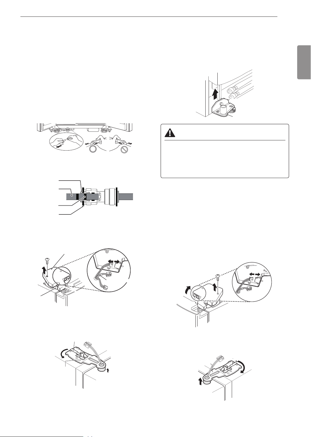
LG LSXS26396S User manual

ENGLISH
OWNER'S MANUAL
SIDE BY SIDE
REFRIGERATOR
Read this owner's manual thoroughly before operating the appliance
and keep it handy for reference at all times.
LSXS26396S
LSXC22396S
MFL67653459
Rev.02_030817
www.lg.com
Copyright © 2017 LG Electronics Inc. All Rights Reserved.

11INSTALLATION
ENGLISH
INSTALLATION
Installation Overview
Please read the following installation instructions rst after purchasing this product or transporting it to another
location.
Unpacking the Refrigerator Choosing the Proper Location Disassembling/Assembling
Connecting the Water Line Leveling and Door Alignment
CAUTION
•Connect to a potable water supply only.

12 INSTALLATION
Unpacking the Refrigerator
WARNING
•Use two or more people to move and install the
refrigerator. Failure to do so can result in back
injury or other injury.
•The refrigerator is heavy. Protect the oor when
moving the refrigerator for cleaning or service.
Always pull the refrigerator straight out when
moving it. Do not wiggle or walk the refrigerator
when trying to move it, as oor damage could
occur.
•Keep ammable materials and vapors, such as
gasoline, away from the refrigerator. Failure to
do so can result in re, explosion, or death.
NOTE
•Remove tape and any temporary labels from
your refrigerator before using. Do not remove any
warning labels, the model and serial number label,
or the Tech Sheet that is located under the front of
the refrigerator.
•To remove any remaining tape or glue, rub the area
briskly with your thumb. Tape or glue residue can
also be easily removed by rubbing a small amount
of liquid dish soap over the adhesive with your
ngers. Wipe with warm water and dry.
•Do not use sharp instruments, rubbing alcohol,
ammable uids, or abrasive cleaners to remove
tape or glue. These products can damage the
surface of your refrigerator.
•Reinstall or adjust shelves as needed. Refrigerator
shelves are installed in the shipping position.
Reinstall shelves according to your individual
storage needs.
Choosing the Proper
Location
Water
Water supply must be easily connected for the
automatic icemaker.
NOTE
•The water pressure must be 20 - 120 psi or 138 -
827 kPa or 1.4 - 8.4 kgf/cm2. If the refrigerator is
installed in an area with low water pressure (below
20 psi or 138 kPa or 1.4 kgf/cm2), you can install a
booster pump to compensate for the low pressure.
Electricity
Use an individual, grounded outlet:115 Volts, 60 Hz,
AC, 15 Amps minimum.
WARNING
•Don't use existing holes unless they are in the
target area. Otherwise, the water supply and
drain hose may be damaged by being crushed
or kinked.
Flooring
To avoid noise and vibration, the unit must be
installed and leveled on a solidly constructed oor. If
required, adjust the leveling legs to compensate for
the unevenness of the oor.
NOTE
•Installing on carpeting, soft tile surfaces, a platform
or weakly supported structure is not recommended.
Ambient Temperature
Install this appliance in an area where the
temperature is between 55 °F (13 °C) and 110 °F
(43 °C).
If the temperature around the appliance is too low or
high, cooling ability may be adversely affected.

13INSTALLATION
ENGLISH
Dimensions and Clearances
•Check the dimensions of the appliance and the installation path to ensure there is sufcient room to move the
refrigerator through doors or narrow openings.
•If an opening is too narrow to t the refrigerator through, remove the refrigerator doors. See Removing/
Assembling the Doors and Drawers in this manual.
•The installation location chosen for the refrigerator should allow space behind the unit for connections and
airow and space in front to open the doors and drawers.
•Too small of a distance from adjacent items may result in lowered freezing capability and increased electricity
consumption charges. Allow at least 24 inches (610 mm) in front of the refrigerator to open the doors, and at
least 2 inches (50.8 mm) between the back of the refrigerator and the wall.
B
A
CDF
G
E
M
- List LSXS26396S LSXC22396S
A Depth without handle 33 2/5"
(848 mm)
29 2/5"
747 mm)
B Width 35 9/10"
(912 mm)
35 9/10"
912 mm)
C Height to Top of Case 68 9/10"
(1750 mm)
68 9/10"
(1750 mm)
D Height to Top of Hinge 70 3/10"
(1785 mm)
70 3/10"
(1785 mm)
E Back Clearance 2"
(50 mm)
2"
(50 mm)
F Depth without Door 28 7/10"
(730 mm)
24 3/5"
(624mm)
GDepth (Total with Door Open
90°)
50 3/5"
(1285 mm)
46 1/2"
(1180 mm)
K Front Clearance 24"
(610 mm)
24"
(610 mm)
M Depth With handle 35 9/10"
(912 mm)
31 4/5"
(807 mm)

14 INSTALLATION
Removing/Assembling
Handles
•When moving the refrigerator through a narrow
opening, removing the doors is preferred.
•The appearance of the handles may vary from what
is shown.
WARNING
When assembling or disassembling the
refrigerator handles:
•Grasp the handle rmly to avoid dropping it.
•Do not swing the handle into nearby people or
animals.
•Make sure that the bracket hole of the handle
ts properly into the stopper bolt of the door.
Assemble the set screws to x the handle into
place.
•Make sure that there is not a gap between the
door and handle after assembling the handle.
Tools Needed
3/32 in. Allen wrench
1/8 in. Allen wrench
1/4 in. Allen wrench
Removing the Refrigerator Handles
1Loosen the set screws (1) with a 3/32 in. Allen
wrench and remove the handle.
2Loosen the mounting fasteners (2) that connect
to the refrigerator door and handle using a 1/4
in. Allen wrench, and remove the mounting
fasteners.
Assembling the Refrigerator Handles
1Assemble the mounting fasteners (1) at both ends
of the handle with a 1/4 in. Allen rench.
2Place the handle on the door by tting the handle
footprints over the mounting fasteners and
tightening the set screws (2) with a 3/32 in. Allen
wrench.
Removing/Assembling the
Doors
If the entrance door is too narrow for the refrigerator
to pass through, remove the refrigerator doors and
move the refrigerator sideways through the doorway.
WARNING
•Use two or more people to remove and install
the refrigerator doors.
•Disconnect the electrical supply to the
refrigerator before installing.
•Do not put hands, feet or other objects into the
air vents or bottom of the refrigerator.
•Be careful when handling the hinge and stopper.
•Remove food and bins before detaching the
doors and drawers.
•Do not hold the handle when removing or
replacing the doors and drawer as the handle
may come off.
Tools Needed
3/32 in. Allen wrench
1/8 in. Allen wrench
1/4 in. Allen wrench

15INSTALLATION
ENGLISH
Removing the Freezer Door (with
Water Line Connection)
1Before removing freezer door, disconnect water
line connectors (one white tube, one blue tube).
•Do not remove freezer door if either the white or
blue tube is still connected.
•Use the support block shipped on the upper
shelf in the refrigerator to keep the front of
the refrigerator tilted up while removing the
connectors.
NOTE
Disassembling/Assembling the Water Lines
Collet
Tube
Insert line
Clip (Correct)
2Loosen the hinge cover screws and remove the
hinge cover. Disconnect all wire harnesses.
Hinge Cover
Upper Hinge
Wire Harness
3Rotate the hinge lever counterclockwise (1) and
lift the upper hinge (2).
(1)
(2)
Hinge Lever
Upper Hinge
4Lift the door to remove it from the lower hinge pin.
Be careful to pull the water lines from behind the
lower hinge pin.
Enough for the water feed tube to be completely
pulled out.
water feed tube
Lower Hinge
CAUTION
•When lifting the hinge free of the latch, be careful
that the door does not fall forward.
•Place the door, inside facing up, on a
nonscratching surface.Be careful not to damage
the water lines.
Removing the Refrigerator Door
1Open the door and remove the top hinge cover
screw.
2Use a at blade screwdriver to pry back the hooks
(not shown) of the hinge cover from the top of
the refrigerator cabinet. Remove the cover and
disconnect all wire harnesses.
3Rotate the hinge lever (1) clockwise. Lift the top
hinge (2) free of the hinge lever latch.
(1)
(2)
Upper Hinge
Hinge Lever

16 INSTALLATION
4Lift the door from the lower hinge pin.
Lower Hinge
CAUTION
•When lifting the hinge free of the latch, be careful
that the door does not fall forward.
•Place the door, inside facing up, on a
nonscratching surface.Be careful not to damage
the water lines.
NOTE
•Do not remove the grease on the surface of the
gasket or hinge.
•Do not remove the sensor assembly in the right
upper hinge cover.
Assembling the Freezer Door
1Feed the water tubes through the lower hinge
pin and place the door onto the lower hinge pin.
Make sure the water hoses are behind the leg to
prevent damage.
NOTE
•Open the door and turn the hose toward the inside.
Water hoses should be behind the leg to prevent
damage.
Correct Incorrect
Disassembling/Assembling the Water Lines
Collet
Tube
Insert line
Clip (Correct)
2Gently press the collet and insert the tube until
only one line shows on the tube.
Correct Incorrect
NOTE
•Water hoses should be cut with a clean, straight
edge to avoid leaks.
3Fit the top over the hinge lever latch and into
place. Rotate the lever clockwise to secure the
hinge.
4Install the grounding screw and connect all the
wire harnesses.
5Hook the tab on the door switch side of the cover,
under the edge of the wire opening in the cabinet
top. Position the cover into place. Insert and
tighten the cover screw.
6Reconnect the water tubes by inserting the tubes
into the connectors. The tube is inserted correctly
when only one guide line is showing out of two.

17INSTALLATION
ENGLISH
4Lift the door from the lower hinge pin.
Lower Hinge
CAUTION
•When lifting the hinge free of the latch, be careful
that the door does not fall forward.
•Place the door, inside facing up, on a
nonscratching surface.Be careful not to damage
the water lines.
NOTE
•Do not remove the grease on the surface of the
gasket or hinge.
•Do not remove the sensor assembly in the right
upper hinge cover.
Assembling the Freezer Door
1Feed the water tubes through the lower hinge
pin and place the door onto the lower hinge pin.
Make sure the water hoses are behind the leg to
prevent damage.
NOTE
•Open the door and turn the hose toward the inside.
Water hoses should be behind the leg to prevent
damage.
Correct Incorrect
Disassembling/Assembling the Water Lines
Collet
Tube
Insert line
Clip (Correct)
2Gently press the collet and insert the tube until
only one line shows on the tube.
Correct Incorrect
NOTE
•Water hoses should be cut with a clean, straight
edge to avoid leaks.
3Fit the top over the hinge lever latch and into
place. Rotate the lever clockwise to secure the
hinge.
4Install the grounding screw and connect all the
wire harnesses.
5Hook the tab on the door switch side of the cover,
under the edge of the wire opening in the cabinet
top. Position the cover into place. Insert and
tighten the cover screw.
6Reconnect the water tubes by inserting the tubes
into the connectors. The tube is inserted correctly
when only one guide line is showing out of two.
Assembling the Refrigerator Door
1Place the door onto the lower hinge pin.
Lower Hinge
2Fit the upper hinge over the hinge lever latch and
into place. Rotate the lever counterclockwise to
secure the hinge.
(1)
(2)
3Reconnect all wire harnesses. Hook the tab on
the switch side of the cover under the edge of the
wire opening in the cabinet top. Position the cover
and replace the screw.
Connecting the Water Line
Before Beginning
This water line installation is not covered by the
refrigerator warranty. Follow these instructions
carefully to minimize the risk of expensive water
damage.
If necessary, call a qualied plumber to correct water
hammer before installing the water supply line to
the refrigerator. Water banging in the pipes, or water
hammer in residential plumbing can cause damage
to refrigerator parts and lead to water leakage or
ooding.
•Turn the icemaker OFF if the refrigerator will be
used before the water line is connected.
•Do not install the icemaker tubing in areas where
the ambient temperatures fall below freezing.
WARNING
•Connect to a potable water supply only.
CAUTION
•To prevent burns and product damage, only
connect the refrigerator water line to a cold water
supply.
•Wear eye protection during installation toprevent
injury.
Water Pressure
You will need a cold water supply.
Water Pressure
models with water lter 20–120 psi
(138 - 827 kPa)
where reverse osmosis
water ltration system is
connected to a cold water
supply
40–60 psi minimum to
reverse osmosis system
(2.8 kgf/cm2– 4.2 kgf/
cm2,or less than 2–3
seconds to ll a cup of 7
oz capacity)

18 INSTALLATION
If the water pressure from the reverse osmosis
system is less than 20 psi or 138 kPa or 1.4 kgf/ cm2
(takes more than 4 seconds to ll a cup of 7 oz or
198 cc capacity):
•Check to see if the sediment lter in the reverse
osmosis system is blocked. Replace the lter if
necessary.
•Allow the storage tank on the reverse osmosis
system to rell after heavy usage.
•If the water pressure remains low, call a licensed,
qualied plumber.
•All installations must be in accordance with local
plumbing code requirements.
Supplies Needed
•Copper or PEX Tubing, ¼ in. outer diameter, to
connect the refrigerator to the water supply. Be sure
both ends of the tubing are cut square. To determine
how much tubing you need, measure the distance
from the water valve on the back of the refrigerator
to the water supply pipe. Then, add 8 feet (2.4 m).
Be sure there is sufcient extra tubing (about 8 feet
[2.4 m] coiled into 3 turns of about 10 in. [25 cm]
diameter) to allow the refrigerator to move out from
the wall after installation.
•Power drill.
•½ in. or adjustable wrench.
•Flat-blade and Phillips-head screwdrivers.
•Two ¼ in. outer diameter compression nuts and
2 ferrules (sleeves) to connect the copper tubing to
the shutoff valve and the refrigerator water valve.
•If your existing copper water line has a ared tting
at the end, purchase an adapter (available at
plumbing supply stores) to connect the water line
to the refrigerator OR cut off the ared tting with a
tube cutter and then use a compression tting.
•Shutoff valve to connect to the cold water line.
The shutoff valve should have a water inlet with a
minimum inside diameter of 5/32 in. at the point of
connection to the COLD WATER LINE. Saddle-type
shutoff valves are included in many water supply
kits. Before purchasing, make sure a saddle-type
valve complies with your local plumbing codes.
NOTE
•A self-piercing saddle type water valve should not
be used.
Water Line Installation Instructions
WARNING
Electric Shock Hazard:
•When using any electrical device (such as a
power drill) during installation, be sure the device
is battery-powered, double-insulated or grounded
in a manner that will prevent the hazard of
electric shock.
Install the shutoff valve on the nearest frequently
used drinking water line.
1Shut off the main water supply.
Turn on the nearest faucet to relieve the pressure
on the line.
2Choose the valve location.
Choose a location for the valve that is easily
accessible. It is best to connect into the side of
a vertical water pipe. When it is necessary to
connect into a horizontal water pipe, make the
connection to the top or side, rather than at the
bottom, to avoid drawing off any sediment from
the water pipe.

19INSTALLATION
ENGLISH
3Drill the hole for the valve.
•Drill a ¼ in. hole in the water pipe using a sharp
bit. Remove any burrs resulting from drilling the
hole in the pipe. Be careful not to allow water
to drain into the drill. Failure to drill a ¼ in. hole
may result in reduced ice production or smaller
cubes.
NOTE
•The hookup line cannot be white, plastic tubing.
Licensed plumbers must use only copper tubing
(NDA tubing #49595 or #49599) or Cross Link
Polyethylene (PEX) tubing.
4Fasten the shutoff valve.
Fasten the shutoff valve to the cold water pipe
with the pipe clamp.
Pipe Clamp
Saddle-Type
Shutoff Valve Vertical Cold
Water Pipe
NOTE
•Commonwealth of Massachusetts Plumbing Codes
248CMR shall be adhered to. Saddle valves are
illegal and use is not permitted in Massachusetts.
Consult with your licensed plumber.
5Tighten the pipe clamp.
Tighten the clamp screws until the sealing washer
begins to swell.
Pipe Clamp
Clamp Screw
Washer
Inlet End
NOTE
•Do not over tighten clamp or you may crush the
tubing.
6Route the tubing.
Route the tubing between the cold water line and
the refrigerator.
Route the tubing through a hole drilled in the wall
or oor (behind the refrigerator or adjacent base
cabinet) as close to the wall as possible.
NOTE
•Be sure there is sufcient extra tubing (about 8 ft.
coiled into three turns of about 10 in. diameter) to
allow the refrigerator to move out from the wall after
installation.
7Connect the tubing to the valve.
Place the compression nut and ferrule (sleeve)
for copper tubing onto the end of the tubing and
connect it to the shutoff valve.
Make sure the tubing is fully inserted into the
valve. Tighten the compression nut securely.
Saddle-Type
Shutoff Valve
Packing Nut
Outlet Valve
Compression
Nut
Ferrule
(sleeve)
8Flush out the tubing.
Turn the main water supply on and ush out the
tubing until the water is clear. Shut the water off at
the water valve after about one quart of water has
been ushed through the tubing.

20 INSTALLATION
9Connect the tubing to the refrigerator.
NOTE
•Before making the connection to the refrigerator, be
sure that the refrigerator power cord is not plugged
into the wall outlet.
•Remove the plastic exible cap from the water
valve.
•Place the compression nut and ferrule (sleeve) onto
the end of the tubing as shown.
•Insert the end of the copper tubing into the
connection as far as possible. While holding the
tubing, tighten the tting.
Tubing
Clamp
¼ in. Compression Nut
Ferrule
(sleeve)
¼ in. Tubing
Refrigerator
Connection
10 Turn the water on at the shutoff valve.
Tighten any connections that leak.
CAUTION
•Check to see if leaks occur at the water line
connections.
Leveling and Door Alignment
Leveling
The refrigerator has two front leveling legs. Adjust the
legs to alter the tilt from front-to-back or side-to side.
If the refrigerator seems unsteady, or the doors do
not close easily, adjust the refrigerator’s tilt using the
instructions below:
1Turn the leveling leg to the left to raise that side
of the refrigerator or to the right to lower it. It may
take several turns of the leveling leg to adjust the
tilt of the refrigerator.
NOTE
•A are nut wrench works best, but an open-end
wrench will sufce. Do not over-tighten.
2Open both doors and check to make sure that
they close easily. If the doors do not close easily,
tilt the refrigerator slightly more to the rear by
turning both leveling legs to the left. It may take
several more turns, and be sure to turn both
leveling legs the same amount.

21INSTALLATION
ENGLISH
Door Alignment
Both the left and right refrigerator doors have an
adjustable nut, located on the bottom hinge, to raise
and lower them to align properly.
If the space between the doors is uneven, follow the
instructions below to align the doors evenly:
Use the wrench (included with the owner's manual)
to turn the nut in the door hinge to adjust the height.
Turn the nut to the right to raise the door or to the left
to lower it.
CAUTION
•Do not overtighten the door adjustment screw.
The hinge pin can be pulled out and the
adjustable range of height is a maximum of 2 in.
(5 cm).
Turning on the Power
•After installing, plug the refrigerator’s power cord
into a 3-prong grounded outlet and push the
refrigerator into the nal position.
CAUTION
•Connect to a rated power outlet.
•Have a certied electrician check the wall outlet
and wiring for proper grounding.
•Do not damage or cut off the ground terminal of
the power plug.
Position the Rrigerator
•Arrange the coil of tubing so that it does not vibrate
against the back of the refrigerator or against the
wall. Push the refrigerator back to the wall.
Start the Icemaker
•If the water line is connected, set the icemaker
power switch to the ON position.
•The icemaker will not begin to operate until it
reaches its operating temperature of 15 °F (–9 °C)
or below. It will then begin operation automatically if
the icemaker power switch is in the ON (I) position.
This manual suits for next models
1
Table of contents
Other LG Refrigerator manuals

LG
LG SXS Refrigerator User manual

LG
LG LRSES2706 Series User manual

LG
LG LFX25971ST Instruction Manual

LG
LG LMX25964 Series User manual

LG
LG LRTB2021BS precautio User manual

LG
LG LRMDC2306 Series User manual

LG
LG GR-B762GVC User manual

LG
LG LFX28995 Series User manual

LG
LG GR-B469BVGW User manual

LG
LG GCD247SL User manual
Popular Refrigerator manuals by other brands

Silver King
Silver King SKR24 Technical manual and replacement parts list

GE
GE GBSL3HCXLLS Dimensions and installation information

Panasonic
Panasonic Easy Take NR-B182W operating instructions

Amica
Amica BK313.3 F A installation guide

Trufrost
Trufrost YC-150EW Operation manual

Zanussi
Zanussi ZB 1420 T Use and care & installation guide