LG WD14030RD6 User manual

WASHING MACHINE
SERVICE MANUAL
MODEL : WD14030RD6
website : http://biz.lgservice.com
e-mail : http://LGEservice.com/techsup.html
CAUTION
READ THIS MANUAL CAREFULLY TO DIAGNOSE PROBLEMS
CORRECTLY BEFORE OFFERING SERVICE.

2
CONTENTS
1. SPECIFICATIONS ............................................................................................................................. 3
2. FEATURES & TECHNICAL EXPLANATION ..................................................................................... 4
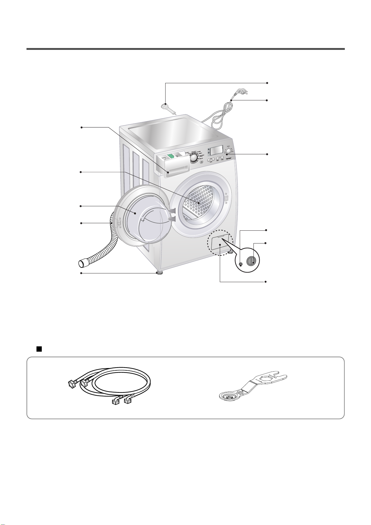
3. PARTS IDENTIFICATION ................................................................................................................. 6
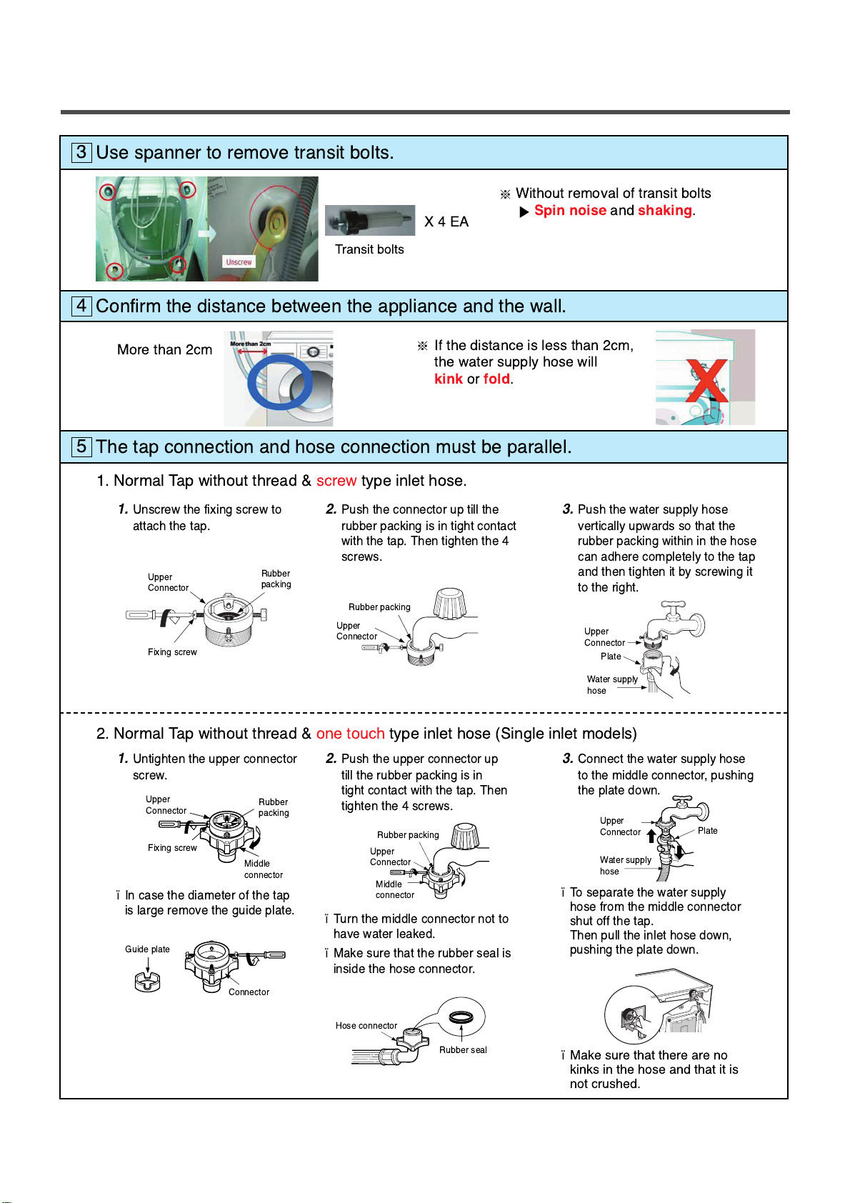
4. INSTALLATION .................................................................................................................................. 7
5. OPERATION ................................................................................................................................... 12
6. WIRING DIAGRAM / PCB LAYOUT ................................................................................................ 14
7. TROUBLESHOOTING......................................................................................................................19
7-1.BEFORE PERFORMING SERVICE ......................................................................................... 19
7-2.LOAD TEST MODE .................................................................................................................. 19
7-3.HOW TO CHECK THE WATER LEVEL FREQUENCY ............................................................ 20
7-4.
HOW TO CHECK THE TEMPERATURE OF EACH THERMISTOR AT OPERATING CONDITION
...... 20
7-5.ERROR DISPLAY ..................................................................................................................... 21
7-6.TROUBLESHOOTING WITH ERROR ..................................................................................... 23
• IE (Water Inlet Error) .............................................................................................................. 23
• UE (Unbalanced Error) ........................................................................................................... 24
• OE (Water Outlet Error) .......................................................................................................... 25
• FE (Over Flow Error) .............................................................................................................. 27
• PE (Pressure Sensor S/W Error) ............................................................................................ 28
• dE (Door open Error) .............................................................................................................. 29
• tE (Thermistor (Heating) Error) ............................................................................................... 30
• LE (Motor Lock Error) ............................................................................................................. 31
8. TROUBLESHOOTING OTHER ...................................................................................................... 33
• No power ................................................................................................................................ 33
• Vibration & Noise during spin ................................................................................................. 34
• Detergent & Softener does not flow in .................................................................................... 35
• Water Leak ............................................................................................................................. 36
9. PART INSPECTION ........................................................................................................................ 38
9-1.FILTER ASSEMBLY (LINE FILTER) ......................................................................................... 38
9-2.DOOR LOCK SWITCH ASSEMBLY ......................................................................................... 39
9-3.STATOR ASSEMBLY ............................................................................................................... 41
9-4.
PUMP MOTOR ASSEMBLY
....................................................................................................... 44
9-5.INLET VALVE ASSEMBLY .......................................................................................................45
10. DISASSEMBLY INSTRUCTIONS .................................................................................................. 46
11. EXPLODED VIEW AND PART LIST .............................................................................................. 54

3
1. SPECIFICATION
ITEM WD14030RD6
POWER SUPPLY
PRODUCT WEIGHT
OPERATION WATER PRESSURE
CONTROL TYPE
WASH CAPACITY
DIMENSION
WASH PROGRAM
RINSE
DOOR SWITCH TYPE
WATER LEVEL
RESERVATION
SENSING LAUNDRY AMOUNT
FUZZY LOGIC
DISPLAY REMAINING TIME
ERROR DIAGNOSIS
POWER AUTO OFF
CHILD LOCK
AUTO RESTART
TIME SAVE
ELECTRICITY
CONSUMPTION
WASHING
SPIN
DRAIN MOTOR
WASH HEATER
DRY HEATER
REVOLUTION
SPEED SPIN
WASH 50 rpm
No Spin/400/800/1000/1400
100-600 kPa (1.0-6.0 kgf / cm
2)
Electronic
8.5 kg (Wash) / 4.5 kg (Dry)
600 mm (W)x640 mm (D)x850 mm (H)
Cotton, Cotton Eco, Mix, Easy Care, Duvet,
Baby Care, Skin Care,
Sports Wear,
Wool, Quick 30, Silent Wash, Rinse+Spin, Dry only, Wash+Dry
Rinse+, Rinse Hold
PTC+Solenoid
10 steps (by sensor)
From 3 hours to 19 hours
Adapted
Adapted
Adapted
10 items
Adapted
Adapted
Not adapted
Adapted
170 W
500 W
30 W
2000 W
1500 W
240 V~, 50 Hz
72 kg

4
2. FEATURES & TECHNICAL EXPLANATION
2-1. FEATURES
Direct Drive System
The advanced Brushless DC motor directly drives the drum without belt and pulley.
Built-in Heater
Internal heater automatically heats the water to the best temperature on selected cycles.
Child Lock
The Child lock prevents children from pressing any Buttons to change the settings during
operation.
More economical by Intelligent Wash System
Intelligent Wash System detects the amount of load and water temperature, and then
determines the optimum water level and washing time to minimize energy and water
consumption.
Low noise speed control system
By sensing the amount of load and balance, it evenly distributes load to minimize the
spinning noise level.
Inverter Direct Drive system
The advance Brushless DC motor directly drives the drum without belt
and pulley.
6 motion
Washer is able to perform various drum actions or a combination of different actions
depending on the wash program selected.
Combined with a controlled spin speed and the ability of the drum to rotate both
left and right, the wash performance of the machine is greatly improved, givong
you perfect results every time.

5
2-2. DETERMINE WASHING TIME BY FUZZY LOGIC
To get the best washing performance optimal time is determined by sensing the water
temperature, selected washing temperature and laundry amount.
2-3. WATER LEVEL CONTROL
This model adopts a pressure sensor which can sense the water level in the tub.
Water supply is stopped when the water level reach the preset level, then washing program proceeds.
Spinning does not proceed until the water in the tub reduces to a certain level.
water
temperature
washing time
rinse time
the best
washing
performance
spin rhythm, time
laundry
amount
FUZZY
LOGIC
selected
washing
temperature
SENSING EFFECT
PROCESSING
DETERMINATION
2-4. THE DOOR CAN NOT BE OPENED
While program is operating.
While Door Lock light is on.

6
3. PARTS IDENTIFICATION
Drawer
Drum
Door
Drain Hose
Adjustable Feet
Shipping Bolts
Control Panel
Power plug
Drain Pump Filter
Drain Plug
Lower Cover Cap
If the supply cord is damaged,
it must be replaced by the
manufacturer or its authorized
service technician in order to
avoid a hazard.
ACCESSORIES
Inlet hose : Hot / Col(2EA) Spanner

7
4. INSTALLATION
INSTALLATION
The appliance should be installed as follows.
Check the conditions of installation area.
1. Check level ground.
On raised foundations or upper level homes, the vibrations can be caused by the type of flooring.
It may be necessary to move the machine to a different area in the home or have the floor
reinforced to properly support the operation of the unit.
2. Check for humidity or any foreign objects under the feet.
Clean the floor, there should be no foreign objects under the feet.
If the unit has foreign objects underneath the feet, this will prevent the unit from being leveled properly
and will cause vibrations and slipping.
Remove any foreign objects, if any from underneath the machine and level unit properly.
See below for examples of foreign objects.
1
Open the box and check appliance condition.
2
horizontal
Carpet Paper Laminated
paper
Purchased
stopper
Base Packing
Washer
Spanner
This leveling (or spanner) wrench must
be used to remove the shipping bolts
and level the unit. This should be kept
for future use.

8
Use spanner to remove transit bolts.
3
Confirm the distance between the appliance and the wall.
4
The tap connection and hose connection must be parallel.
5
Without removal of transit bolts
Spin noise
and
shaking
.
X4EA
Transit bolts
More than cm If the distance is less than cm,
the water supply hose will
kink
or
fold
.
1. Normal Tap without thread & screw type inlet hose.
1.
Unscrew the fixing screw to
attach the tap.
2.
Push the connector up till the
rubber packing is in tight contact
with the tap. Then tighten the 4
screws.
3.
Push the water supply hose
vertically upwards so that the
rubber packing within in the hose
can adhere completely to the tap
and then tighten it by screwing it
to the right.
1.
Untighten the upper connector
screw.
2.
Push the upper connector up
till the rubber packing is in
tight contact with the tap. Then
tighten the 4 screws.
3.
Connect the water supply hose
to the middle connector, pushing
the plate down.
Incase the diameter of the tap
is large remove the guide plate. Turn the middle connector not to
have water leaked.
Make sure that the rubber seal is
inside the hose connector.
Toseparate the water supply
hose from the middle connector
shut off the tap.
Then pull the inlet hose down,
pushing the plate down.
Make sure that there are no
kinks in the hose and that it is
not crushed.
. Normal Tap without thread & one touch type inlet hose (Single inlet models)
Upper
Connector
Fixing screw
Guide plate
Connector
Rubber packing
Upper
Connector
Rubber packing
Upper
Connector Plate
Water supply
hose
Rubber seal
Hose connector
Upper
Connector
Middle
connector
Rubber
packing
Upper
Connector
Fixing screw
Middle
connector
Rubber
packing
Upper
Connector
Plate
Water supply
hose

9
Connect Drain Hose.
6
Connect power plug.
7
If the drain hose is not installed properly, the unit will not drain properly.
This allows water to back flow into the unit which can cause odors.
Refer to Owner Manual for proper drain hose installation.
The odor could also be coming from the home’s drain to which the drain hose is attached.
In this type of drain hose installation, the odor could be coming from the standpipe.
This odor can come up the drain hose and into the unit.
Pour a cup or two of bleach or vinegar down the home drain
and let it sit for 24 hours before running another cycle.
This will help eliminate odor from the home drain.
If a cycle is started too soon after doing this, it will not help the issue.
Connect the power plug to the wall outlet. Avoid connecting several electric devices,
it may be the cause of a fire.
about 100 cm
about 145 cm
about 105 cm
Laundry tub
Max. 100cm
min. 60cm
Max. 100cm
min. 60cm
Retainer
Tie
strap
Hose
min. 60 cm
max. 100 cm

10
Rubber Cup
Check the horizontality with a level (Gage).
8
Step 1
If washing machine legs are loose or not Screwed in, then tighten with the spanner wrench.
Using the level, level the washing machine from front to back and side to side.
Step 2
Use the spanner wrench to adjust Legs until level and try the Diagonal test.
Step 3
Perform a Rinse and Spin with some clothing in the machine.
To do this, put 2~3kg of clothing in the unit, turn on the unit, Select the Rinse+Spin
and then start. When the unit reaches the spin cycle, watch for vibrations.
If the unit is vibrating, make small adjustments to the leg until they subside. (Repeat step 2)
Step 4
Tighten the lock nut against the base of the machine to lock the position leg.
Lower the foot until there is no gap between floor and foot.
And only use adjustment rubber when difference at the leg adjustment is more than 10mm.
Place your right hand on the back, right corner and your left hand on the front,
left corner of the unit, then attempt to rock the unit from corner to corner.
Then, move your right hand to the front, right side and your left hand to the
back, left corner and attempt to rock the unit from corner to corner.
If the unit is level, it will not rock. However, if the unit is not level, it will rock.
If the unit rocks, it will be necessary to adjust the leveling feet of the unit.
Adjust the foot under the hand that is on the front of the machine.
How to perform a diagonal test:
A level
Higher
Tighten
Adjustable feet
Diagonal test
Tighten
Adjustable feet
Higher
Tighten
Adjustable feet
Lower
4620ER4002B
(Gray)
for Wooden floors
Rubber Cup
4620ER4002A
(Black)
for Tile floors
Lock nut
10mm
Adjustable bolt
Tighen the lock nut
Floor
No Gap
Floor
No Gap
Floor
Gap

12
se this button to turn the
power
.
Rotate the
to select the cycle
designed for different
types of fabric and soil
levels.
Time Delay : Allows the start of any cycle to be delayed
for 3~19 hours.
Favorite : Favorite program allows you to store a
customized wash cycle for future use.
Pre Wash : se this option for load that needs protreatment.
Adds 17minutes pre wash and drain.
Additional programs
Cycle Selector
POWER
Option Button
Medic Rinse : For best results or for cleaner rinsing, you
can choose Medic Rinse option.
Intensive : If the laundry is heavily Soiled, Intensive option is effective.
Time Save :
This option can be used to reduce the time of a wash program.
To use this option press option button before wash program is started.
Rinse+ : sed to additional rinse, which may assist in removing
traces of detergent residue.
Rinse Hold : -Rinse Hold is selected by pressing the spin button
repeatedly this function leaves clothes in the machine; suspended in
the water after the last rinse without entering into spin.
-Toproceed through to a drain or spin.once the rinse hold function is
completed using to Program dial and Spin button to the required program.
(Spin)
se this button to Start/
Stop the washer.
Start/Pause
T
a
si
5. OPERATION

13
This display shows:
In case of abormal operation, error
indications are displayed.
(
)
See troubleshooting
a) the estimated time remaining in the
cycle when operating.
EST. Time remaining
Tub Clean course can be set by
Holding rinse +temp button
Tub Clean is a special cycle to
clean the inside of the washer.
Tub Clean
Dry Selector knob
Dry programs selected by rotating
dry knob.
[Lower Temp. - Iron Dry - Cupboard
Dry - Eco Dry - Time(30,60,120)]
can be selected.
he Beep on/off function can be set by pressing
nd holding the Option and Spin button
multaneouly.
se this option to prevent unwanted
use of the washer. Press and hold
Option left and right button
for 3 seconds to lock/unlock control.
When Child lock is set, CHILD LOCK
lights and all buttons are disabled
except the Power button. You can
lock the washer while it is operating.
Child Lock
Spin, Temp. Button
To change the spin speed,
Press the Spin button to cycle
through available options.
Select a water termperature
based on the type of load you
are washing.

14
6.
WIRING DIAGRAM / PCB LAYOUT
1. DRY
2. C/DUCT
3. WASH
4. AQUA
YL
Y
L
Y
L
B
K
B
K
/
W
H
V
L
/
W
H
V
L
/
W
H
G
N
S
B
L
S
B
L
R
D
/
W
H
R
D
W
H
/
R
D
W
H
/
R
D
B
L
/
W
H
B
N
B
N
Y
L
W
H
G
Y
R
D
R
D
B
L
B
L
W
H
G
Y
R
D
B
L
W
H
Y
L
B
K
W
H
GY
NA WH
WH
NA
WH
WH
FAN MOTOR
THERMISTOR
PRESSURE
SWITCH
AG Wash AQUA
(OPTION)
C/Duct
(OPTION)
Dry
(OPTION)
DRY Model
WH WH WH
WH
BL
WH
WH
Motor
VUW
Ha
Hb
GND
RD
123 123 4
4
123
123
123
123
123
1212
12
3123
1
1
12
2
23123
123
1234
12345
12345
1234
123
123
123
26457813
26457813
123
123
123
5.
PRESSURE SWITCH
6.
COMMON
7.
PRESSURE SWITCH
8. AG
POWER PWB
DISPLAY
PWB
Wiring Diagram 1/3
1. DRY
2. C/DUCT
3. WASH
4. AQUA
YL
Y
L
Y
L
B
K
B
K
/
W
H
V
L
/
W
H
V
L
V
L
V
L
/
W
H
G
N
S
B
L
S
B
L
S
B
L
BN
/
YL
YL
/
RD
R
D
RD
RD
RD
RD
AC
WH
AC
RD BL
GN/YL
GN/YL
GN
/
YL
GN
/
YL
GN/YL
BL
BL
BL
BK
BK
BK
WH
GY
YL
BK
BK
BK
RD
HEATER
DRY
Ta p
Relay
Ta p
Relay
Ta p
Relay
Ta p
Relay
DRY Model, Only
THERMOSTAT
AG HEATER
WASHING HEATER
RD
B
K
BN
/
YL
S
B
L
R
D
/
W
H
R
D
W
H
/
R
D
Y
L
/
R
D
W
H
/
R
D
B
L
/
W
H
B
N
B
N
B
N
/
Y
L
Y
L
W
H
G
Y
R
D
R
D
B
L
B
L
W
H
W
H
W
H
/
B
K
W
H
P
K
GND L S
AG
SENSOR
B
K
/
W
H
Y
L
/
B
K
G
Y
/
W
H
Y
L
G
Y
R
D
R
D
B
L
R
D
B
L
R
D
O
R
B
K
B
N
Y
L
G
N
B
L
R
D
O
R
B
K
B
N
Y
L
G
N
R
D
O
R
B
K
B
N
Y
L
G
N
B
L
B
K
B
K
BK
BK BKBK
BK BK
WH WH
SBL
BK BK BK
BN BN
BN NA RDRD
WH
W
H
Y
L
B
K
W
H
GY
YL YL
YLYL
SBLNA NA
NA
NA
NA
NA
NA
RD
CON2
WH
WH
NA
WH
WH
FAN MOTOR
THERMISTOR
PRESSURE
SWITCH
AG Wash AQUA
(OPTION)
C/Duct
(OPTION)
Dry
(OPTION)
DRY Model
WH WH WH
WH
BL
WH
WH
Motor
VUW
Ha
Hb
GND
WHBL
BK
SBL
DRAIN
PUMP
RM Model, Only
DOOR LOCK SWITCH
CIRCULATION
PUMP
WH
RLM
HOT
V/V
(OPTION)
PRE
V/V
MAIN
V/V
INLET VALVE
AG
V/V
DRY
V/V
(OPTION)
RD
RD
123 123 4
4
123
123
123
123
123
1212
12
3123
1
1
12
2
23123
123
12
12 12 12 12 12
132
1
1
1
2
2
3
332
123
123
34
12345
12345
1234
123
123
123
26457813
2645781
1
1
87654321
2
2
3
3
4
4
1
1
1
1
2
2
2
2
3
3
3
3
1
1
2
2
3
3
412341212
12
34567 1234567
1234567
12345678
123456
1
1
1
2
3
4
1
1
14
23
14
23
14
43
12
23
1
11
22
22
1
12
12
1
22
2
3
4
3
5
1
3
5
23456
1234 56
78
1234567
12345678
12345678
1234
4
3
123
123
123
1. Common
2. Door S/W
3. Main V/V
4. Drain Pump
1. Dry V/V
3. AG V/V
1. Pre-Wash V/V
2.
Circulation Pump
3. Hot V/V
5.
PRESSURE SWITCH
6.
COMMON
7.
PRESSURE SWITCH
8. AG
PO
PO
WER PWB
WER PWB
DISPLAY
PWB
PWB
Full Wiring Diagram
1/3 2/3 3/3

15
V
L
V
L
S
B
L
BN
/
YL
YL
/
RD
R
D
RD
B
K
BN
/
YL
S
B
L
Y
L
/
R
D
B
N
/
Y
L
W
H
W
H
/
B
K
W
H
P
K
GND L S
AG
SENSOR
B
K
/
W
H
Y
L
/
B
K
G
Y
/
W
H
Y
L
R
D
B
K
B
K
BK
BK BKBK
BK BK
WH
SBL
BK BK BK
BNBN NA RDRD
WH
YL YLSBLNA
NA
BL
BK
SBL
DRAIN
PUMP
RM Model, Only
DOOR LOCK SWITCH
CIRCULATION
PUMP
WH
RLM
HOT
V/V
(OPTION)
PRE
V/V
MAIN
V/V
INLET VALVE
AG
V/V
DRY
V/V
(OPTION)
12 12 12 12 12
132
1
1
1
2
2
3
332
123
123
1
1
87654321
2
2
3
3
4
4
1
1
1
1
2
2
2
2
3
3
3
3
1
1
2
2
3
3
41234
1234
4
1. Common
2. Door S/W
3. Main V/V
4. Drain Pump
1. Dry V/V
3. AG V/V
1. Pre-Wash V/V
2.
Circulation Pump
3. Hot V/V
POWER PWB
DISPLAY
PWB
Wiring Diagram 2/3

16
RD
RD
RD
AC
WH
AC
RD BL
GN/YL
GN/YL
GN
/
YL
GN
/
YL
GN/YL
BL
BL
BL
BK
BK
BK
WH
GY
YL
BK
BK
BK
RD
HEATER
DRY
Ta p
Relay
Ta p
Relay
Ta p
Relay
Ta p
Relay
DRY Model, Only
THERMOSTAT
AG HEATER
WASHING HEATER
RD
R
D
B
L
R
D
O
R
B
K
B
N
Y
L
G
N
B
L
R
D
O
R
B
K
B
N
Y
L
G
N
R
D
O
R
B
K
B
N
Y
L
G
N
B
L
WH
BN
YLYL
NA
NA
NA
NA
RD
CON2
WH
RD
12 12
12
34567 1234567
1234567
12345678
123456
1
1
1
2
3
4
1
1
14
23
14
23
14
43
12
23
1
11
22
22
1
12
12
1
22
2
3
4
3
5
1
3
5
23456
123456
78
1234567
12345678
12345678
POWER PWB
DISPLAY
PWB
Wiring Diagram 3/3

17
PCB Layout (Main)
Earth Wire Connector
Dry Heater
Dry Fanmotor

18
Before servicing ask the customer what the trouble is.
Check the adjustments. (Power supply :220-240V~, Removal of transit bolts etc..)
Check the troubles referring to the troubleshooting.
Decide service steps referring to disassembly instructions.
Then, service and repair.
After servicing, operate the appliance to see whether it works OK or NOT.
7. TROUBLESHOOTING
7-1. Checking before SVC
7-2. LOAD TEST MODE
1Press and Hold ‘Option (Left)’ & ‘Rinse’ buttons
and then press ‘Power’ button.
2The washer must be empty and the controls must be in the off state.
3Press Power with above two buttons pressed and then buzzer will sound.
4Press the Start/Pause button repeatedly to cycle through the test modes
1
2
3
4
5
6
None
1 time
2 times
3 times
4 times
5 times
6 times
7 times
9 times
10 times
11 times
12 times
13 times
14 times
15 times
16 times
Turns on all lamps and locks the door.
Tumble clockwise.
Low speed Spin.
High speed Spin.
Inlet valve for prewash turns on.
Inlet valve for main wash turns on.
Inlet valve for hot water turns on.
Inlet valve for steam turns on.
Tumble counterclockwise.
Heater turns on for 3 sec.
Circulation pump turns on.
Drain pump turns on.
Dry Fan / Dry Heater turn on.
Water level Sensor for Steam
Steam Heater turns on for 1.2 sec.
Off
rpm (42~50)
rpm (55~65)
rpm (125~155)
Water level frequency (25~65)
rpm (42~50)
Water temperature
Water level frequency (25~65)
Dry Fan / Dry Heater 5min
Water level frequency of TSG (0~255)
TSG temperature
-
Number of times the
Start/Pause button is pressed Check Point Display Status

19
7-3. HOW TO CHECK THE WATER LEVEL FREQUENCY
7-4. HOW TO CHECK THE TEMPERATURE OF EACH THERMISTOR
AT OPERATING CONDITION.
Press the Favorite and Option (Left) button simultaneously.
Press the Option (Left) and Temp. button simultaneously.
The digits means water level frequency. (10-1kHz)
ex) 241 : Water level frequency = 241 x 10-1kHz
24.1 kHz
Thermistor in tub temperature.

20
If you press the Start/Pause button in error condition, any error except will disappear and the
machine will change into the pause status.
In case of , , if the error is not resolved within 20 sec., and in case of other errors,
if the error is not resolved within 4 min., power will be turned off automatically and the error only will be
blinked. But in the case of , power will not be turned off.
7-5. ERROR DISPLAY
ERROR SYMPTOM CAUSE
WATER INLET
ERROR
•Not reached the water level(246) within 8 minutes
after water supplied or not reached to the preset
water level within 25 minutes. Page 23
1
UNBALANCE
ERROR
•The appliance is tilted.
•Laundry is gatherd to one side. Page 24
2WATER OUTLET
ERROR
•Not fully drained within 10 minutes. Page 25
3OVERFLOW
ERROR
•Water is over flowing (over level 8).
If " " is displayed, the drain pump
operates to drain the water
automatically. Page 27
4PRESSURE SENSOR
S/W ERROR
•The sensor pressure switch is out of order.
Page 28
5DOOR OPEN
ERROR
•In case of operating the reservation function or the
other function with door opened. Close the door,
then the error display is resolved.
•The door switch is out of order. Page 29
6
THERMISTOR(HEATING)
ERROR
•The THERMISTOR is out of order. Page 30
7
Other manuals for WD14030RD6
1
Table of contents
Other LG Washer manuals