'XHWRRXUSROLF\RIFRQWLQXRXVSURGXFWLQQRYDWLRQVRPHVSHFL¿FDWLRQVPD\FKDQJHZLWKRXWQRWL¿FDWLRQ
/*(OHFWURQLFV86$,QF(QJOHZRRG&OLIIV1-$OOULJKWVUHVHUYHG³/*´LVDUHJLVWHUHGWUDGHPDUNRI/*&RUS 5
Safety Precautions
SAFETY PRECAUTIONS
CAUTION
LG Electronics U.S.A., Inc., is not responsible for any piping
calculations, refrigerant leaks, degradation of performance,
or any other potential problems or damages as a result of
interconnecting piping, their joint connections, isolation
valves, introduced debris inside the piping system, or other
problems caused by the interconnecting piping system.
This product is engineered to be used for comfort cooling /
heating. It is not to be used in applications that require preci-
sion cooling or heating such as data centers, food preserva-
tion, wine coolers, refrigeration and / or freezer applications.
There is risk of property damage.
3URYLGHVXI¿FLHQWSURWHFWLRQDJDLQVWWKHHIIHFWVRIHOHFWUR-
PDJQHWLF¿HOGV(0)DQGHOHFWULFDOQRLVH
Inverter equipment, private power generators, high-frequency medical
equipment, or radio communication equipment will cause the air condi-
tioner to malfunction.
Do not install this product in a location that is noise sen-
sitive. Provide additional acoustical treatment as needed.
Occupants could be disturbed by the operation noise.
Do not install the product where it is exposed directly to
ocean winds.
Sea salt in the air will cause the product to corrode. Corrosion will cause
SURGXFWPDOIXQFWLRQRULQHI¿FLHQWRSHUDWLRQ
Periodically check that the frame is not damaged.
There is a risk of equipment damage.
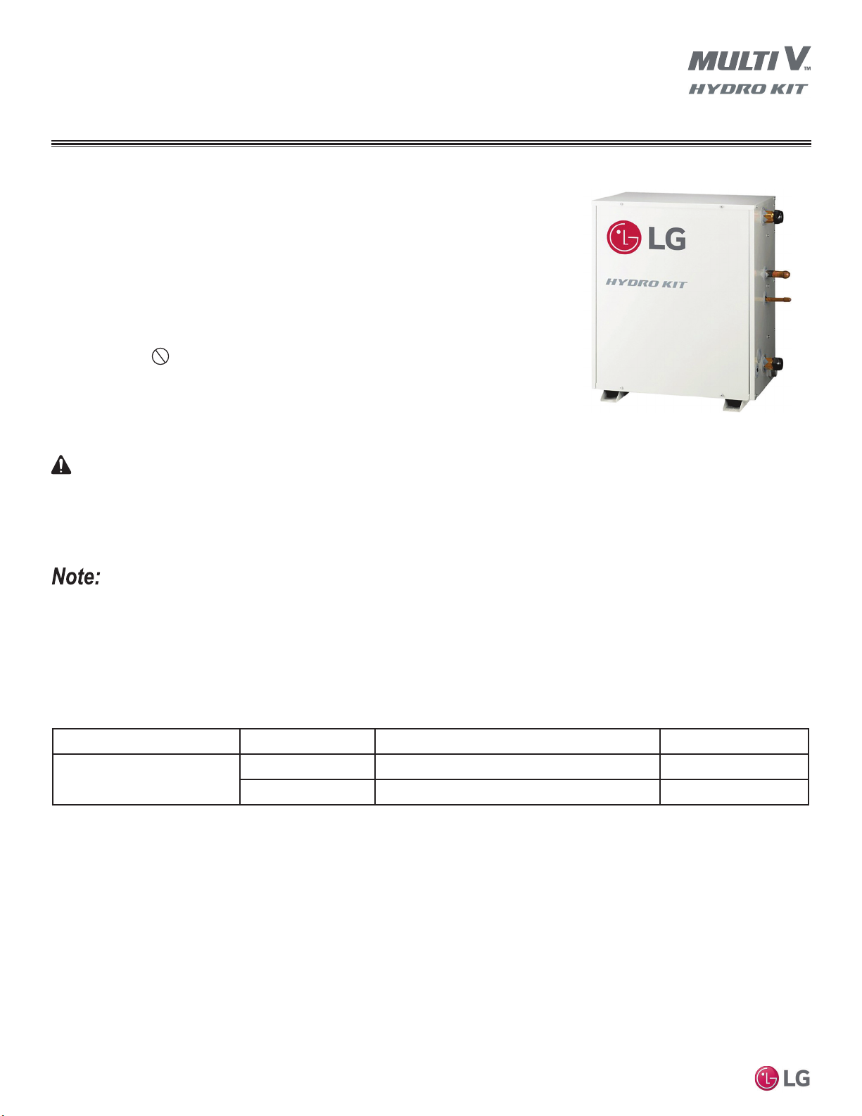
The Hydro Kit must be installed indoors; do not install the
unit outside and / or in a highly humid environment.
There is risk of product malfunction, failure and property damage.
Install the unit in a safe location where no one can step on or
fall onto it. Do not install the unit on a defective stand.
There is a risk of unit and property damage.
When installing the unit in a low-lying area, or a location that
is not level, use a raised concrete pad or concrete blocks to
provide a solid, level foundation.
This prevents water damage and abnormal vibration.
Always check for system refrigerant leaks after the unit has
been installed or serviced.
Low refrigerant levels will cause product failure.
Properly insulate all cold surfaces to prevent “sweating.”
Cold surfaces such as uninsulated piping can generate condensate that will
drip and cause a slippery surface condition and / or water damage to walls.
The Hydro Kit must be kept in an upright and level position
during installation.
To avoid oil migration from the onboard compressor, vibration, and water leaks.
Verify the piping system has been properly evacuated, and
the system’s refrigerant charge is correct before commis-
sioning and after any repair is made.
Improper system evacuation and / or an improper refrigerant charge will
cause product malfunction.
Properly insulate all cold surfaces when installing this product.
Cold surfaces such as uninsulated piping can generate condensate that
could drip, causing a slippery surface that creates a risk of slipping, fall-
ing, and personal injury.
Always use tools designed for R410A refrigerant.
Improper installation will result in refrigerant leaks, frostbite, suffocation,
physical injury, and or death.
The Hydro Kit water circuit could require antifreeze. Always ask
the dealer or an LG trained technician to install the water circuit.
$QWLIUHH]HLVWR[LFWKHUHLVDULVNRISK\VLFDOLQMXU\RUGHDWK
Follow manufacturer’s instructions when performing leak and
evacuation tests. Do not use compressed air, oxygen, or
ÀDPPDEOHJDVHV
7KHUHLVDULVNRI¿UHRUH[SORVLRQZKLFKZLOOUHVXOWLQSK\VLFDOLQMXU\RU
death.
When installing refrigerant piping, consider pipe expansion.
Improper pipe installation will lead to pipe fatigue / failure, a rapid re-
lease of refrigerant, frostbite, suffocation, physical injury, and or death.
Only use the parts included or approved for the product.
Improper installation will result in physical injury or death.
Be very careful when transporting the unit.
• Hydro Kit weight and size preclude one person carrying the unit. Use two or more people to transport the unit because there is a risk of
personal injury. Keep the unit upright.
• Some products use polypropylene bands for packaging. Do not use polypropylene bands to lift the unit.
• Suspend the from the base at specified positions. Support the unit a minimum of four points to avoid slippage from rigging apparatus.