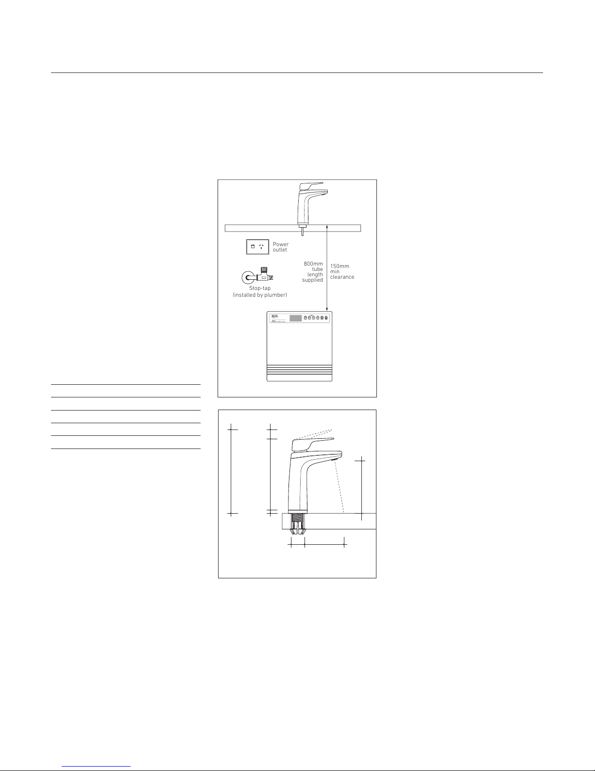
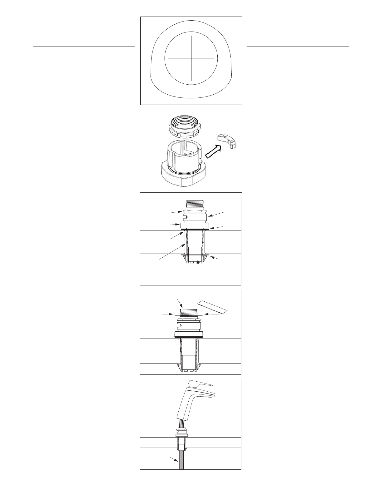
Billi B-6000 User manual

1
B–6000
Boiling and Chilled
Filtered Water System
Installation guide

2
—Billi B–6000 system components
Before commencing installation,
ensure you have identified the following:
1. Underbench module
2. Dispenser upper with tubing
3. Dispenser base & mount
4. Barb locking bush
5. 4mm chrome screw & allen key
6. Large washer
7. Tube spring clamps x 3
8. 450mm flexible braided hose
9. Drain fittings including
John guest fittings
10. 3/8 tube connected with adapter
to 3/16 black tube
11. ½ inch drill bit
12. Behind door panel:
a. filter cartridge(s)
b. user guide
c. warranty registration card
—Determine unit location
Plan the installation. Dispenser tube lengths,
position of power and water outlets, required
air space around the underbench module and
access for service must be considered before
cutting tube lengths. Refer to Diagrams 1 and 2
and the table below for clearances around unit.
Unit must be installed horizontally with display
panel facing to front of cupboard. The B-6000 is
designed for internal installation only.
Model B-6000
Height 340mm
Width 315mm
Depth 350mm
Min side clearance 10mm
—Water supply
The B-6000 must only be connected to
a cold water supply. A 15mm stop tap
(not supplied) is to be installed in an easily
accessible position within 450mm from
the B-6000 water supply inlet. The B-6000
incorporates a certified pressure limiting
and backflow prevention device.
Do not fit an additional pressure
limiting valve.
Water supply pressure:
Min. 250kPa, max. 1000 kPa.
Supply temp: min. 5°C, max. 30°C.
Do NOT install with water that is
microbiologically unsafe or with water of
unknown quality without adequate disinfection
before or after the system. Systems certified
for cyst reduction may be used on disinfected
water that may contain filterable cysts.
—Power requirements
A single 3 pin GPO is required. A dedicated
circuit should be provided and must be
fitted with an earth leakage protection
device (RCD). An externally fitted RCD device
is acceptable. All B-6000 models are supplied
with a 1-metre flex cord and plug.
—Drainage
B-6000 models require a drainage point such
as a dishwasher nipple. Use the nipple adaptor
fitting supplied or the clamp-on drain adaptor
(also supplied with system). Clamp-on drain
adaptor must be installed above the water seal
on the sink side of the water trap. The B-6000
dispenser incorporates an externally vented
air gap.
IMPORTANT: This Billi appliance is to be
installed by a licensed tradesperson in
accordance with AS 3500.4 or AS/NZ 3500.4.2
and in compliance with applicable state
regulatory requirements. For correct operation
of this appliance, it is essential to observe the
manufacturer’s instructions.
1. Install dispenser assembly
Determine position of dispenser mounting
hole in sinktop or benchtop. Dispenser base
template (Diagram 3) may be cut out and
used to assist in correct positioning. Hole size
required is ø32mm.
—Stainless steel sinktop
A suitable 32mm hole punch (Part no: 857901)
is available as an accessory
from Billi Pty Ltd. If possible, cut hole with
die mounted below the sinktop surface so
that burr is pulled downwards. Alternatively,
remove burr and radius edge of hole with fine
file. This allows barbed dispenser mount to
slide smoothly into mounting hole. Oil hole
punch regularly. Lubricate surface to be cut
with detergent.
—Timber/laminate benchtop
Maximum benchtop thickness is 50mm.
Cut 35mm hole in appropriate position.
When drilling through a particle board
bench top, take care to avoid a large chip
breaking away as drill breaks through
underside surface. We recommend drilling
a small pilot hole through benchtop, partially
drilling the 35mm hole from underneath and
then completing drilling the hole from above.
The large 30mm washer supplied may be used
to secure barb where underside particle board
bench top has chipped away.
2. Activate Dispenser Swivel Feature
To activate the swivel feature of your
dispenser, you will need to remove the
locking piece from the dispenser base.
Simply push out the piece as show in
Diagram 5. This will allow the tap to
move 45 degrees to the left and right.
3. Fit dispenser base
a. Cut a 32mm hole in sinktop or benchtop.
Remove burr if protruding upwards.
b. Press barbed mounting shaft through
mount hole. Finger tighten nut.
c. Insert barb locking bush as shown
in Diagram 6.
d. Ensure barb is centred in mount hole
before tightening. Check position of
base ring and gasket.
e. Moderately tighten locking nut using
multigrips or spanner. Take care to avoid
overtightening nut which may break the
plastic threaded shaft.
f. Place large washer over thread as shown
in Diagram 7.
g. Cut off excess threaded shaft with a
hacksaw, using washer as a cutting guide.
Installation
requirements.
Power
outlet
Stop-tap
(installed by plumber)
800mm
tube
length
supplied
150mm
min
clearance
Installing the
dispenser.
205mm
175mm
20mm
bench
thickness
1mm-48mm
Diagram 2
10mm
130mm
35mm 95mm
Diagram 1

3
IMPORTANT: Remove burrs and check internal
bore is completely smooth.
4. Fit dispenser head assembly
a. Lay dispenser head assembly alongside
mounting base assembly.
b. Feed dispenser tubing and loom through
centre hole in the following order:
i. Dispenser power cord.
ii. 5mm and 10mm black drain tubes
(water-cooled)
iii. Grey vent silicone tube. Feed tube
until reducing join passes through
mount assembly – see Diagram 8.
iv. Red and blue silicone tubing.
To assist feeding the tubing, we
recommend using silicone spray
lubricant. Do not attempt to force
tubing through with a pointed object
as silicone tube is easily punctured.
Check tubing is not kinked or twisted.
c. Turn dispenser head assembly to
approximately 60° from the straight
ahead position of dispenser base.
Slide head assembly onto base assembly
whilst gently pulling tubing downwards
from underneath to prevent tubing
bunching and kinking. Mounting lugs
will pass nut and slide down the
3 grooves on the swivel bearing.
d. Once fully down, turn dispenser to
straight ahead position. Fit chrome
plated M4 retaining screw to lower
rear threaded hole and tighten using the
allen key supplied. Check dispenser now
swivels smoothly 45° in each direction.
Silicone
tubing
dispenser base
template
Diagram 4
Diagram 6
Swivel
Bearing
Gasket
Washer if
required
Barb locking bush in position
Barbed
Mounting
Shaft
Ensure burr is
remover & edge
is radiused
Base Casting
Locking Nut
Diagram 7
Cut o
excess
thread
Remove burrs after cutting and
ensure internal bore is smooth
Washer
Diagram 5
Diagram 8
1. Flush water supply
Flush water supply pipework before installing
the underbench unit by connecting 450mm
flexible braided hose to the supply tap and
running water into a bucket.
2. Install underbench unit
Take care to observe minimum clearances.
Ensure there is adequate access to service
the unit.
3. Connect dispenser tubing
and electrical plug
Connect all tubing and electrical plug as shown.
Ensure correct orientation of dispenser power
plug before insertion. Trim tubes to correct
lengths using a sharp knife or plastic tube
cutter. Avoid leaving excess tubing which
will sag, trapping water. Fit spring clamps
supplied to retain silicone rubber tubing
to barbed fittings. 5mm black refrigeration
cooling tube is fitted to a compression nut
type fitting. Refer to Diagram 10. Nut to be
finger tightened only.
IMPORTANT: Boiling outlet (red), vent tube
(grey) and 10mm black drain tube must not
be kinked and must be installed with a
Continual fall.
4. Connect Drain Tube
a. Clip white john guest fitting into sliver
hose clamp.
b. Drill ½ inch hole (using drill bit provided)
into drainage point (pipe).
c. Fit hose clamp to drainage pipe, ensuring
the while john guest fitting surrounds the
hole drilled.
d. Take the drain hose connection provided
and connect the 3/8 hose into the
drain clamp.
e. Connect the 3/16 hose into the condenser
outlet on the unit.
5. Remove the filter packing from under the
filter canister
Installing the
dispenser.
Installing
underbench module.

4
—Turn On Water Supply
Turn on the water supply tap and
check there are no leaks.
—Turn On Electricity
Turn on power switch. Check normal
time display is showing. Status line
should display ‘INITIAL FILL’. Boiling
and chilled water tanks are now filling.
Dispenser icons flash orange slowly.
—Cold Water
During the initial fill, cold water valve
automatically opens to fill the cold tank.
After approximately 1 minute, cold water
will begin to flow from the dispenser outlet.
Water will continue to run for a further minute
to flush and condition the filters.
—Hot Water (Auto Boiling Calibration)
Auto Boiling Point Calibration:
The hot tank will first fill to the height
of the low level sensor. The water is then
heated until it reaches boiling point. The unit
will continue to boil for up to 30 seconds while
the temperature sensor calibrates.
WARNING: Steam and small amount of hot
water may be discharged from the taps and
vent during this period. While calibration is
underway the hot water indicator (red) will
double blink rapidly. The hot water set point is
calibrated 1.5°C below the boiling point. Once
calibrated, the unit will resume normal
operation and the calibration data will be saved.
The unit will not re-calibrate under normal
circumstances.
—Setting the programs
The B-6000 operational settings have been
factory set for a typical installation. Clock is
set to Eastern Standard Time (EST). Refer to
B-6000 User Guide for setting instructions.
In some installations, boiling water delivery
settings may need to be changed as
outlined below.
—Setting the programs
The B-6000’s boiling water flow rate
slows briefly as water first enters the
cup to prevent splashing. Correct timing
of the moment of reduced flow is dependent
on the length of the tube between the B-6000
module and the dispenser. The standard
timing is set for a tube length of 500mm but
this setting can be simply altered to suit the
installation. After installation, measure the
length of the red tube from the underside
of the dispenser to the boiling water outlet
fitting. If the measured length is less than
450mm or greater than 550mm, the
correct value should be set in as follows:
1. Press SELECT. Display changes
to menu selection mode.
2. Press 4 times. Shaded cursor
shows ‘INITIAL SETUP’.
3. Press SELECT. Display shows:
4. Press SELECT. ‘0500 mm’ flashes.
5. Press or buttons to enter the
correct tube length.
6. Press SELECT.
7. Press BACK twice to return
to normal display.
—Boiling water flow rate
The boiling water flow rate can be adjusted
to suit the installation or user preference.
Extended tube lengths will require the
pump speed to be increased.
1. To adjust, use the selection procedure
as described above in Steps 1, 2 and 3.
2. Press SELECT. Shaded cursor
shows ‘Pump Speed 015’.
3. Press SELECT. ‘015’ flashes.
4. Press or buttons to increase or
decrease. Range is between 10 and 20.
5. Press SELECT.
6. Press BACK twice to return to
normal display.
—Calibrating boiling water temperature
(Manually)
The boiling water temperature has been factory
calibrated. Because water boils at a slightly
lower temperature at elevated altitudes, the
factory-set temperature may be too high for
units installed at certain
inland locations. If the local altitude is greater
than 500 metres above sea level,
a calibration cycle should be performed.
The procedure is as follows;
1. Use the selection procedure as
described above, in Steps 1, 2 and 3.
2. Press SELECT twice to select
‘Calibrate Boiling Water’.
3. Press SELECT twice to begin cycle.
4. The unit will fill and heat (if not yet
up to operating temperature before
cycle begins).
—CAUTION
Steam will discharge from the vent
outlet located between the hot and
cold water outlets.
Once correct boiling temperature is
established, the B-6000 recalibrates
its internal settings and the display
panel returns to normal.
Commissioning.
Billi Pty Ltd
42 Lucknow Crescent, Thomastown
Victoria 3074 Australia
Telephone +61 3 9469 0400
Facsimile +61 3 9469 0499
www.billi.com.au
Designed and manufactured in Australia.
As Billi Pty Ltd has a policy of continual
improvement, all details are subject
to change without notice. All goods
are sold subject to our published terms
and conditions. Billi is a registered
trademark. 1012
WARNINGS.
For continued safety of this appliance
it must be installed, operated and
maintained in accordance with the
manufacturer’s instructions.
—Your appliance should be installed by
a suitably qualified tradesperson.
—For correct operation of this appliance
it is essential to observe the instructions
as outlined in this booklet.
—Do not use this appliance with water
that is microbiologically unsafe or with
water of unknown quality without adequate
disinfection before or after the system.
Systems certified for cyst reduction may
be used on disinfected water that may
contain filterable cysts.
—Filter replacement must be performed
at intervals of not more than 6 months.
—Use this appliance only as directed in
these instructions and only for its designed
purpose.
—This appliance is not intended for use by
persons (including children) with reduced
physical, sensory or mental capabilities, or
lack of experience and knowledge, unless
they have been given supervision or
instruction concerning use of the appliance
by a person responsible for their safety.
—Children should be supervised to ensure
that they do not play with the appliance.
—DANGER: The operation of the thermal
cut-out indicates a possibly dangerous
situation. Do not reset the thermal cut-out
until the water heater has been serviced
by a qualified person.
—WARNING: Do not connect any restrictor
or pressure relief device to the vent pipe
of this water heater if installed.
—If the supply cord is damaged, it must be
replaced by the manufacturer, its service
agent or similarly qualified persons in
order to avoid a hazard.
—New hose-sets supplied with the appliance
are to be used and old hose-sets should
not be re-used.
Other manuals for B-6000
1
Table of contents
Other Billi Water System manuals
Popular Water System manuals by other brands

Waterco
Waterco OXISWIM Quick reference guide

gledhill
gledhill HIU-DCH Design, installation & servicing instructions

Grunbeck
Grunbeck MR25 Operation manual

ProMinent
ProMinent Dulcodes D operating instructions

Irrigatia
Irrigatia Solar Automatic C60 instructions

Zip
Zip HydroTap BCS Series Installation and operating instructions

McDonnell & Miller
McDonnell & Miller Uni-Match WFE-24 instruction manual

Rheem
Rheem RSG75-48BP Use & care manual

Perma-Trade
Perma-Trade PT-P25 instruction manual

Everpure
Everpure Carbon Filter Wrap CWS-10 Specification sheet

Santevia
Santevia Gravity Water System Maintenance manual

OptiPure
OptiPure Sanit-ICE Installation & operation manual