LI-COR li-7200 User manual

LI-7200 Intake Cap and Dust Filter
This document describes the intake cap and dust filter for
the LI-7200. The intake cap (part number 9972-072) is
designed to minimize water vapor and CO2frequency atten-
uation. The dust filter (part number 9972-073) helps prevent
dust and pollen from entering the LI-7200 optical cell.
Installing the Intake Cap
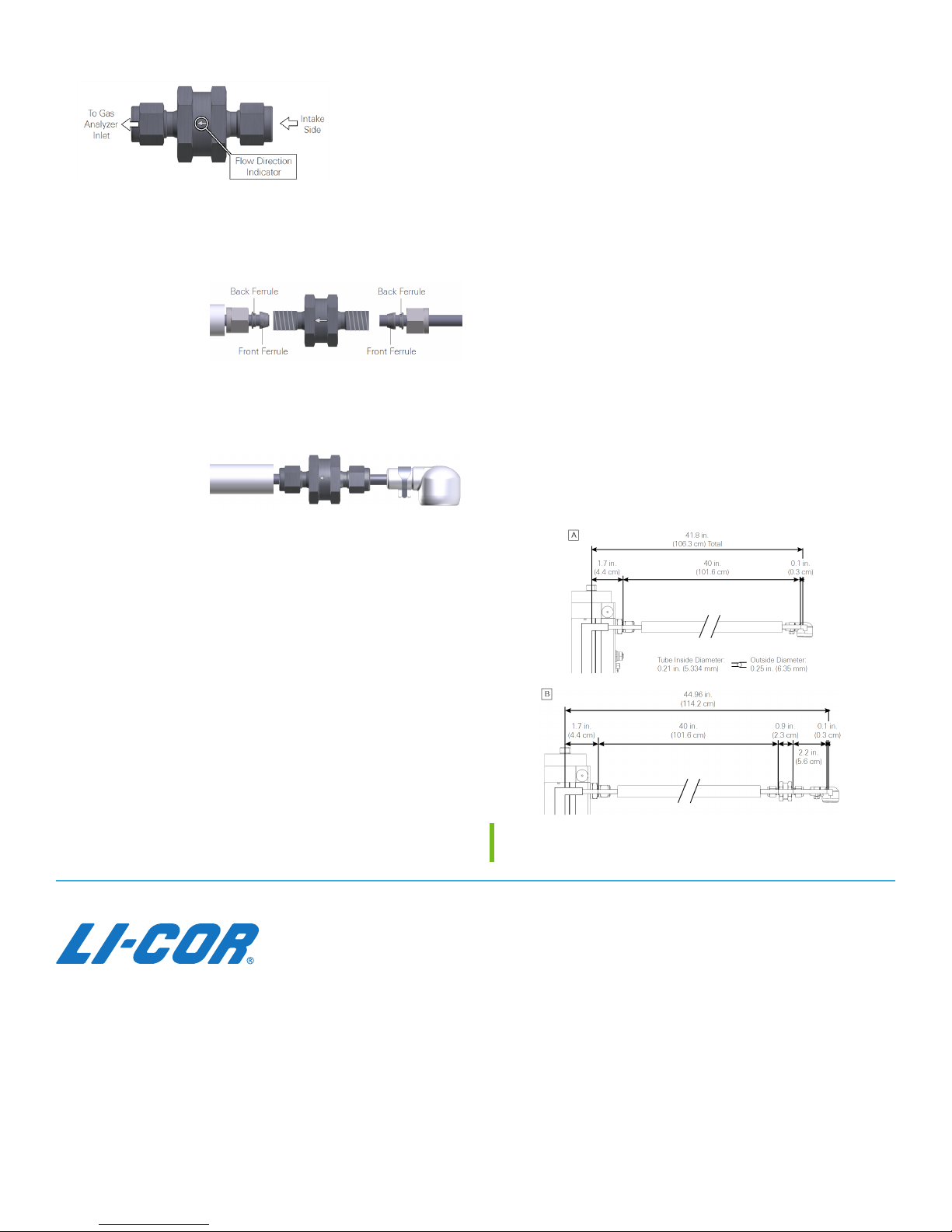
The intake cap kit includes the following components:
Intake Cap (includes screen and hose clamp).
Spare screen, retaining ring, and hose clamp.
The intake cap attaches to the standard ¼" diameter intake
tube (part number 9972-053) and heated intake tube. To
install the intake cap:
1If necessary, remove the old cap and all of its com-
ponents from the intake tube.
2Place one hose clamp over
the intake tube and slide
the new intake cap over
the stainless steel intake tube until it stops.
The intake tube should extend ~1
inch (2.54 cm) into the cap.
3Using a pliers, grasp the hose
clamp to expand it. Slide it over
the inlet cap as shown and release it.
Note: Do not expand the hose clamp more than necessary.
Doing so can permanently deform the clamp.
Cleaning the Intake Cap and Screen
To clean the cap and screen, remove the intake cap assembly
and back-flush it with compressed air or water. You can
immerse the intake cap assembly in boiling water for a few
minutes or soak it in an ultrasonic water bath. Usually, you
should not have to remove the screen from the cap. If you
do need to remove the screen:
1Insert a small screwdriver between the screen and
intake cap.
Use caution to avoid damaging the cap and deforming
the screen.
2Carefully pull the screen
out of the cap.
3Assembly is the reverse of
removal.
Be sure the screen is seated
fully in the cap.
Dust Filter
The dust filter (part number 9972-073) is a Swagelok® 2-
micron filter that will reduce the amount of dust that enters
the gas analyzer optical cell. Under normal conditions, the
filter should extend the amount of time that can pass before
you need to clean the optical cell. Use the filter in envir-
onments that have airborne dust and pollen that can con-
taminate the optical cell.
Important: The filter does not completely eliminate the
need to regularly clean the optics. Regular cleaning is
required in order to prevent measurement drift that can
occur when certain kinds of contaminants accumulate on
the cell windows.
The filter will increase the power requirements of your
system. As the filter becomes dirty, the flow module
will use more power to maintain the same flow rate.
The filter may affect H2O frequency response, espe-
cially when it is dirty. (This can be addressed with addi-
tional frequency response corrections.)
The effectiveness of the filter depends upon the site
conditions, overall level of dust in the air, and the char-
acteristics of the dust (fine vs. coarse dust particles).
The dust filter includes:
Swagelok filter with two compression fittings.
Two inch (5.08 cm) by ¼ inch stainless steel intake
tube extension.
Installing the Dust Filter
The dust filter installs between the end of the intake tube
and the intake cap. To install it:
Installation Guide
1

1Remove the intake cap.
Carefully observe the flow arrow indicator on the filter.
Air should flow in the direction of the arrow.
2Remove the compression fitting from the intake side
of the filter.
3Install the nut,
front ferrule, and
back ferrule over
the short stain-
less steel pipe.
Be sure the tube is fully seated in the filter. Tighten the
fitting to hand tight, then about ½ turn more using
9/16" and 1" wrenches.
4Install the nut,
front ferrule, and
back ferrule on
the intake tube.
5Install the inlet cap.
Maintaining the Filter
How do you know when to clean the filter? Dust will accu-
mulate in the filter over time. The rate of dust accumulation
will depend upon the amount of dust in the air and the
particle size of dust. Therefore, it is difficult to predict
exactly when the filter should be cleaned.
As dust builds up in the filter, the flow module will use
more power to maintain the flow rate. So, the best indicator
of the filter status is a change in the power required to run
the flow module. When you install a new filter, record the
Flow Drive (%), or log that variable with your data. Over
time, compare the flow drive % with the initial value. The %
will increase as the filter becomes clogged, indicating that
the pump must work harder to move air through the filter.
Clean the filter before the Flow Drive (%) exceeds 90%.
Cleaning: If possible, use an ultrasonic water bath, then
back-flush the filter with compressed air and allow the filter
to dry before reinstalling. Otherwise, immerse the filter in
boiling water for a few minutes or soak it over night and
then back-flush it with compressed air. As a good practice,
clean the intake cap whenever you clean the filter.
The ferrules/compression fittings do not need to be removed
from the intake tubes when the filter is removed. They can
be reused.
Insulated Intake Tube Specifications
Outside Diameter: 0.25" (6.35 mm)
Inside Diameter: 0.21" (5.334 mm)
Wall Thickness: 0.020" (0.51 mm)
Length: 40" (101.6 cm)
Intake tube path length when assembled: 102 cm
Intake tube path length with Swagelok® filter: 106.5 cm
Material: 304 Stainless Steel
Figure 1. Dimensions for the intake tube and cap (A) and
the intake filter assembly (B).
©2017 LI-COR, Inc. 05/17
984-14359 Rev 3
Global Headquarters
LI-COR Biosciences
4647 Superior Street
Lincoln, Nebraska 68504
Phone: +1-402-467-3576
Toll free: 800-447-3576
Fax: +1-402-467-2819
envsales@licor.com
envsupport@licor.com
www.licor.com/env
LI-COR Distributor Network:
www.licor.com/env/distributors
Regional Offices
LI-COR GmbH, Germany
Serving Andorra, Albania, Cyprus, Estonia, France, Germany,
Iceland, Latvia, Lithuania, Liechtenstein, Malta, Moldova,
Monaco, San Marino, Ukraine, and Vatican City.
LI-COR Biosciences GmbH
Siemensstrasse 25A
61352 Bad Homburg
Germany
Phone: +49 (0) 6172 17 17 771
Fax: +49 (0) 6172 17 17 799
envsales-gmbh@licor.com
envsupport-gmbh@licor.com
LI-COR Ltd., United Kingdom
Serving Denmark, Finland, Ireland, Norway, Sweden, and UK.
LI-COR Biosciences UK Ltd.
St. John’s Innovation Centre
Cowley Road
Cambridge
CB4 0WS
United Kingdom
Phone: +44 (0) 1223 422102
Fax: +44 (0) 1223 422105
envsales-UK@licor.com
envsupport-UK@licor.com
Other manuals for li-7200
1
Popular Water Filtration System manuals by other brands

PREMIER TECH
PREMIER TECH Rewatec Ecoflo ST-500 owner's manual

Solmetex
Solmetex Hg5 Installation and maintenance instructions

Filters itm
Filters itm HYDRAULIC-200-H-INOX user manual

Eaton
Eaton UM15 operating instructions

Trigano
Trigano J-PSC064 Instruction and maintenance manual

Mitte Home
Mitte Home MHDE01 user manual

Beko
Beko CLEARPOINT S040 Installation & operation instructions

Vagner Pool
Vagner Pool Cantabric Installation and maintenance manual

Club Hydrate
Club Hydrate Perfect Pitcher owner's manual

Schier
Schier PP2 installation guide

FCI Watermakers
FCI Watermakers MAX-Q+ User manual & installation guide

LG
LG WCD56US2 owner's manual