Liberty Pumps Omnivore 2460 Series User manual

©Copyright 2017 Liberty Pumps Inc. All rights reserved 1
IMPORTANT:
Prior to installation, record Model, Serial Number, and
Code Number from pump nameplate for future reference.
MODEL ________________________
SERIAL ______________________
CODE ______________________
INSTALLATION
DATE _______________________
Installation Manual
5651000J
Features:
LSG or LSGX Series 2HP Grinder Pump
24” dia. Basin available in 60”, 72”, 84”, or 96”
depths
Guide Rail System
Preassembled including ball & check valves
Simplex Panel with Alarm –or- Automatic Pump
with Alarm
Contents
1. General Information
2. Precautions / Pre-Installation
3. Installation Instructions
4. Maintenance & Troubleshooting
5. GR20 Assembly
2460 / 2472 / 2484/ 2496 - Series Simplex Grinder Systems
7000 Apple Tree Avenue
Bergen, NY 14416
Phone: (800) 543-2550
Fax: (585) 494-1839
www.libertypumps.com

©Copyright 2017 Liberty Pumps Inc. All rights reserved 2
1General Information
Maximum fluid temperature: 140F (60C)
The LSG or LSGX Series grinder pump and the control panel are supplied with their own separate
Installation/Operation/Maintenance manuals. Ensure that you have received these manuals, and that you read and understand them
prior to installing this unit. Your familiarity with the grinder pump manual and the control panel manual is critical. This installation manual
gives a brief overview of the system, and deals mainly with inspection and installation of the basin, but it does not cover the specifics of
the pump operation or the control panel operation. If you have any questions, call customer service at (800) 543-2550 or visit
www.libertypumps.com.
2Precautions / Pre-Installation
Risk of electric shock. Always disconnect the pump from the power source before handling or making adjustments.
These pumps are not to be installed in locations classified as hazardous in accordance with the National Electric Code, ANSI/NFPA
70.
The electrical connections and wiring for a pump installation should only be made by qualified personnel.
This pump is supplied with a grounding conductor or a grounding-type attachment plug. To reduce the risk of electric shock, be
certain that the grounding conductor is connected only to a properly grounded control panel or, if equipped with a grounding-type
plug, that it is connected to a properly grounded, grounding-type receptacle.
Do not bypass grounding wires or remove ground prong from attachment plugs.
Do not remove cord and strain relief, and do not connect conduit to pump.
Do not use an extension cord.
This pump requires separate, properly fused and grounded branch circuit. Make sure the power source is properly sized for the
voltage and amperage requirements of the motor, as noted on the pump nameplate.
The installation must be in accordance with the National Electric Code and all applicable local codes and ordinances.
Sump and sewage pumps often handle materials which could cause illness or disease. Wear adequate protective clothing when
working on a used pump or piping.
Never enter a pump basin after it has been used. Sewage and effluent can emit several gases which are poisonous.
Pre-installation checklist:
1. Inspect system unit upon arrival to ensure that there is no
shipping damage. Pay careful attention to the condition of
the fiberglass basin, control floats, pump guide rail brackets,
and control panel. Notify the carrier immediately if there is
any damage.
2. Read all instructions and familiarize yourself with the unit’s
operation prior to proceeding with the installation.
3. A qualified licensed electrician should install and test all
electrical circuits.
4. Check to ensure that your power source is adequate to
handle the pump amperage as noted above and on the
pump nameplate. Ensure that the electrical supply circuit is
equipped with fuses or breakers of the proper capacity.
5. A separate 115V branch circuit should be installed for the
alarm. We do not recommend splitting the incoming pump
power circuit to power the control circuit.
6. All electrical connections should be tested to ensure that a
proper ground has been established

©Copyright 2017 Liberty Pumps Inc. All rights reserved 3
3Installation Instructions
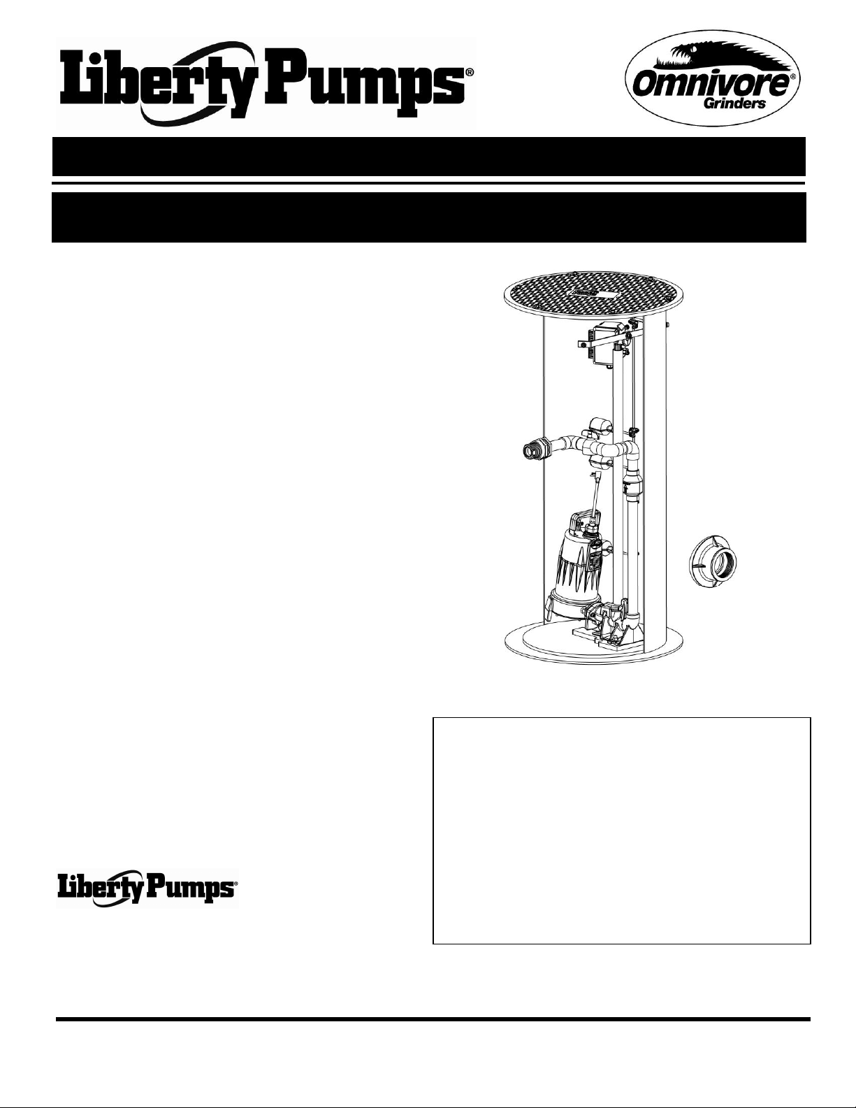
1. Excavation: Excavate the hole for the basin as small as possible, with a minimum base diameter of 38”. Never place the basin in
direct contact with rocks or other sharp objects. Place enough fine, 1/8" to 3/4" pea gravel or 1/8" to 1/2" washed, crushed stone at
the bottom of the excavation to create a minimum of 12 inches stone or gravel after compaction. Do not use sand or native soil as
backfill*. Properly compact underneath the basin to provide a solid, level base that can support the weight of the filled basin. If a
concrete pad will be used under the basin, the compacted stone sub-base can be reduced to 6 inches.
2. Connections & Backfill: Pour enough concrete over and around the anti-floatation flange to anchor the basin and prevent
upward movement. Connect 1¼” schedule 80 PVC pipe to the pump discharge. Do not reduce the size of the discharge piping,
and do not increase the discharge piping to larger than 2”. The remainder of the discharge line should be as short as possible with
a minimum number of turns. Connect the inlet line to the 4” fiberglass inlet hub with a rubber donut (Liberty #6112000). Connect
the electrical coupling to 2” electrical conduit and run the power and float cords through the conduit to the control panel. The
remaining backfill should be only fine, 1/8" to 3/4" pea gravel or 1/8" to 1/2" washed, crushed stone. Do not use sand or native soil
as backfill*. Do Not exert heavy pressure or run heavy equipment over the backfill material, as it may cause tank collapse.
*Other backfill options may be available –consult the factory for special instructions relative to your situation.
3. Venting: The fiberglass basin provided with the system
must be completely sealed and properly vented in order to
meet health and plumbing code requirements. The system
is designed to be vented through the inlet to an existing
building vent stack. In order to accomplish this, there must
be no traps between the system inlet and the nearest
building vent stack connection. See Figure A for an
example. If this is not possible or desirable in your
application, a vent flange or grommet can be installed in a
hole cut into the solid fiberglass cover.
4. Control Panel:
Risk of Electric shock: This pump is
supplied with a grounding conductor. To reduce the risk of
electric shock, be certain that it is connected only to a
properly grounded earth wire. All electrical circuitry should
be installed in accordance with the National Electric Code
(NEC) and all applicable local codes or ordinances.
The control panel that is an integral part
of this complete unit is supplied with its own separate
Installation/Operation/Maintenance manual. Ensure that
you have received this manual, and that you read and
understand it prior to installing this unit. Your familiarity with
the control panel manual is critical.
Per UPC code, a separate 115V branch circuit should be
installed for the alarm circuit. We do not recommend
splitting the incoming pump power circuit to power the
control circuit.
Connect the grinder pump leads and the float switch leads
to the control panel in accordance with the instructions
included with those units.
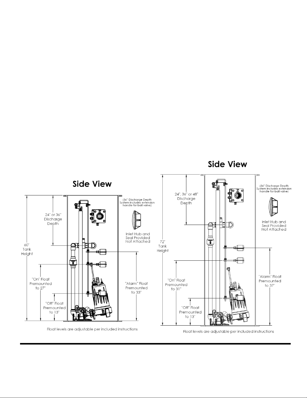
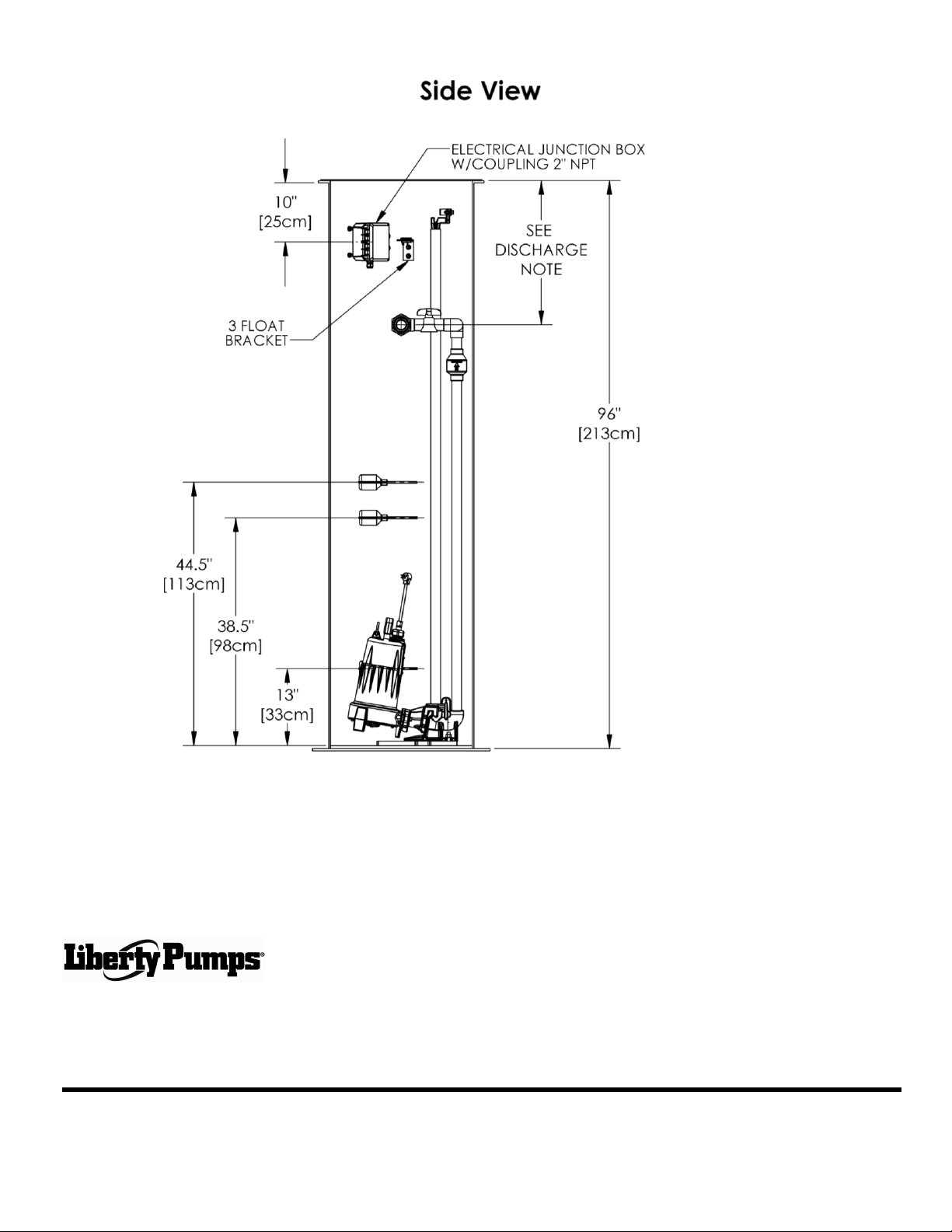
5. Float Switches:
The float switches are pre-mounted on a quick tree. For
quick tree removal, loosen the cord nut, locking clamp, and
pull the tree straight out of the tank. The pump cycle is pre-
set at the factory at 14” for 2460LSG (approximately 28
gallons), 18” for 2472LSG (approximately 35 gallons), 20”
for 2484LSG (approximately 39 gallons), and 24” for the
2496LSG (approximately 47 gallons). The pump cycle can
be adjusted by loosening the cord clamp and moving the
“on” float up or down. We do not recommend adjustments
of more than 3” in either direction – please call the factory if
you need to adjust the pump cycle beyond this
recommended level.
6. Testing and Startup: Follow the testing and startup
procedures found in the LSG / LSGX Series and control
panel manuals.
2460LSG
OR
Figure A –Inlet Venting
2460LSG
OR
2472LSG
OR
2484LSG
OR
2496LSG

©Copyright 2017 Liberty Pumps Inc. All rights reserved 4
4Maintenance and Troubleshooting
The LSG or LSGX Series grinder pump and control panel are supplied with their own separate
Installation/Operation/Maintenance manuals. Ensure that you have received these manuals, and that you read and understand them
prior to installing this unit. Your familiarity with the grinder pump manual and the control panel manual is critical. Please follow the
Maintenance and Troubleshooting procedures provided in those manuals.
5GR20 Quick Disconnect Assembly
The GR20 quick disconnect assembly provided with your grinder package system is designed to allow easy installation and removal
of the pump. Please ensure that installation is done as per the diagrams below.
DISCONNECTED POSITION OPERATING POSITION
GUIDE RAIL PIPE
DISCHARGE PIPE

©Copyright 2017 Liberty Pumps Inc. All rights reserved 5
3 Year Limited Warranty
Liberty Pumps, Inc. warrants that pumps of its manufacture are free from all factory defects in material and workmanship
for a period of 3 years from the date of purchase. The date of purchase shall be determined by a dated sales receipt
noting the model and serial number of the pump. The dated sales receipt must accompany the returned pump if the date
of return is more than 3 years from the "CODE" (date of manufacture) number noted on the pump nameplate.
The manufacturer's obligation under this Warranty shall be limited to the repair or replacement of any parts found by the
manufacturer to be defective, provided the part or assembly is returned freight prepaid to the manufacturer or its
authorized service center, and provided that none of the following warranty-voiding characteristics are evident:
The manufacturer shall not be liable under this Warranty if the product has not been properly installed; if it has been
disassembled, modified, abused or tampered with; if the electrical cord has been cut, damaged or spliced; if the pump
discharge has been reduced in size; if the pump has been used in water containing sand, lime, cement, gravel or other
abrasives, or in water exceeding the advertised temperature; if the product has been used to pump chemicals or
hydrocarbons; if a non-submersible motor has been subjected to excessive moisture; or if the label bearing the serial,
model and code number has been removed.
Liberty Pumps, Inc. shall not be liable for any loss, damage or expenses resulting from installation or use of its products,
or for consequential damages, including costs of removal, reinstallation or transportation.
There is no other express warranty. All implied warranties, including those of merchantability and fitness for a
particular purpose, are limited to three years from the date of purchase.
This Warranty contains the exclusive remedy of the purchaser, and, where permitted, liability for consequential
or incidental damages under any and all warranties are excluded.
2460-Series
2472-Series

©Copyright 2017 Liberty Pumps Inc. All rights reserved 6
2484-Series
2460LSG24-A

©Copyright 2017 Liberty Pumps Inc. All rights reserved 7
7000 Apple Tree Avenue
Bergen, NY 14416
Phone: (800) 543-2550
Fax: (585) 494-1839
www.libertypumps.com
2496-Series
This manual suits for next models
11
Table of contents