Lidén Weighing LI-101 User manual

LI-101 User Manual

1
Table of Contents
Safety Precaution........................................................................................................................2
Chapter 1 Keyboad Instruction....................................................................................................3
Chapter 2 Specifications ............................................................................................................. 4
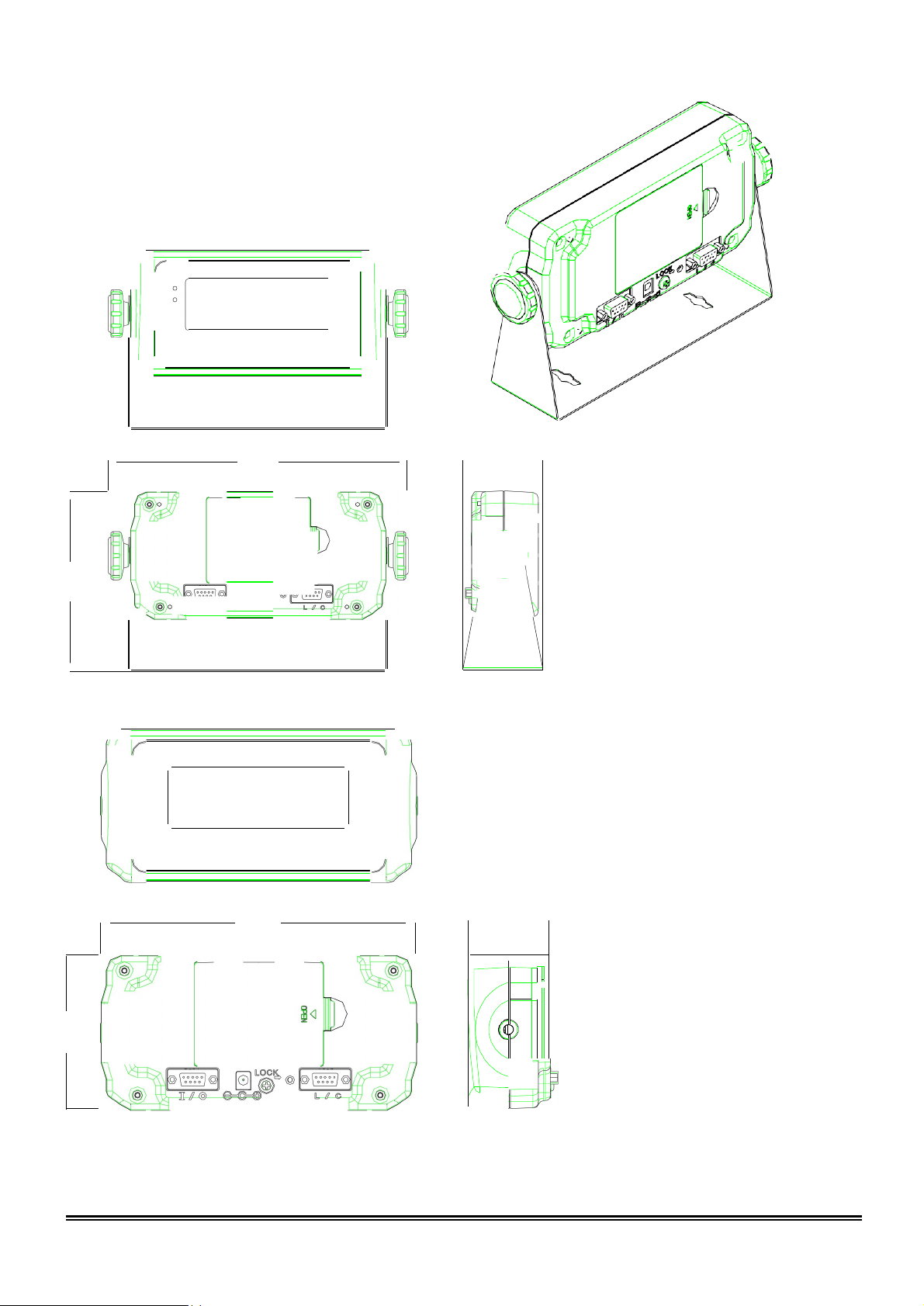
Chapter 3 Front and Rear Panels ............................................................................................... 5
3-1 Front Panel ....................................................................................................................5
3-2 Rear Panel..................................................................................................................... 6
Chapter 4 Installation ..................................................................................................................7
4-1 Load Cell........................................................................................................................7
4-2 Dimension......................................................................................................................8
4-3 Battery Assemble........................................................................................................... 9
Chapter 5 External Function Parameter Setting........................................................................ 10
5-1 External Function Setting..............................................................................................11
5-2 RS232 Setting.............................................................................................................. 13
Chapter 6 Internal Setting Mode ............................................................................................... 18
6-1 Specification Setting .................................................................................................... 19
6-2 Internal Weight Calibration........................................................................................... 22
6-3 Internal Function Setting.............................................................................................. 24
6-4 Error Messages ........................................................................................................... 26
Chapter 7 Special Function ....................................................................................................... 27
7-1 Animal Scale Setting.................................................................................................... 27
7-2 Dual Range Resolution Switch Function...................................................................... 28
7-3 Pre-tare Function ......................................................................................................... 29
7-4 Resolustion Switch Function........................................................................................ 29
7-5 Peak Hold Function. .................................................................................................... 30
Chapter 8 Interface................................................................................................................... 31
8-1 OP-01 RS232/RS485 Serial Output (with RTC) ...........................................................31
Chapter 9 Maintenance ............................................................................................................ 33
9-1 Default Recovery for All Parameters............................................................................ 33
9-2 Default Recovery for General Function Parameters .....................................................33
9-3 Self-diagnosis Mode.................................................................................................... 33
9-3-1 Program Version Number ............................................................................... 34
9-3-2 7-segment Display Testing ........................................................................................34
9-3-3 Keypad & Calibration Switch Testing.................................................................... 34
9-3-4 AD Conversion Value.............................................................................................34
9-3-5 EEPROM Testing ...................................................................................................34
9-3-6 RTC Time & Date Testing ......................................................................................34
9-3-7 RS-232 Serial Output Interface Testing ( OP-01 )............................................34
Appendix 7-SEGMENT DISPLAY CHARACTERS..................................................................... 35

2
Safety Precaution
Turn off power before installing or disassembling.
Keep the product away from sunshine. The temperature range for operation
is 0℃~ +40℃.
To connect the ground is a must for this equipment. The ground impedance
is less than 100Ω.
Never connect the ground with other equipments which are huge in power
consumption.
No ground or incorrect ground connecting might cause the electric shocks or
breakdowns.
Before using the product
Thank you for purchasing LI-101 indicator.
In order to operate smoothly, to last the durability, and to
reduce the chance of breakdown for this product, please
read the following User Manual carfully.

3
.
Chapter 1 Keyboad Instruction
Function
Operation
Description
General Function
Setting
Press and hold ENTER ,
andthenpress
F1
Refer to <Chapter 5> External
Function Parameter Setting for details
Weighing Parameter
Setting
Adjust calibration
switch to ON
Setting for decimal point, capacity,
division, zero tracking, and unstable
detecting, etc. Refer to 6-1
Specification Setting for details.
Calibration
Adjust calibration
switch to ON
Refer to 6-2 Internal Weight
Calibration for operation.
Self-diagnosis Mode
While turning on with
countdown, press and
hold Z E RO .
Refer to 9-3 Self-diagnosis Mode
for details.
Default Recover for
All Parameters
Adjust calibration switch
Refer to 9-1 for details.
to ON, and then press
and hold
F1
ENTER
.
Default Recovery for
General Function
Parameters
While turning onwith
countdown, press and
hold
F1
ENTER
Refer to 9-2 for details.
During the operation, use the following keys to complete all
the
works.
ZER
To add the value flashing
F2
To move the cursor rightward
TA
R
To reduce the value flashing
ENTER
Storage setting
GROS
NET
To move the cursor leftward
To abort setting/to exit
ESC

4
Chapter 2 Specifications
Analog Specification
Load Cell Current: DC 5V −5% 60mA (Up to Four 350Ω Load Cells)
Max. Load Cell Input Voltage: 16 mV
Input Sensitivity: 0.15µV/D or more
Conversion Rate: Approximately 120 times/sec. (max.)
Resolution: 20 bits
Digital Specification
Display: LCD, 6 digits, height 25.4x10mm, LEDbacklight
(Black digits for FM; red digits for FMR)
Display Frequency: 50 times/sec.(max.)
Display Range: - 999999 ~ 999999
Min. Division: 1, 2, 5, 10, 20, 50
Decimal Point: 0, 0.0, 0.00, 0.000, 0.0000
Memory: Calibration parameter and function setting are all stored in EEPROM.
Optional Interface
OP-01 RS-232 / RS-485 (Includes RTC Function)
Power Requirement
Adaptor Spec.: Input 120/230VAC 50~60Hz, output 9V/1000mA
Optioanl 2 types of batteries: 6V Hi-MH rechargeable battery kit (5pcs )
or
General batteries (5pcs)
Max. Power Consumption:
110mA (with 4 Load Cells + backlight + RS-232 interface)
NiMH battery → 15 hours
General battery → 24 hours
45mA (with 1 Load Cell + no backlight + no RS-232 interface)
NiMH battery → 36 hours
General battery → 60 hours
Others
Operation Temperature: 0℃~ 40℃
Operation Humidity: < 85% R.H.
Dimension: W 49.5
•
L193
•
H134 (mm)
Weight: 700g

5
Chapter 3 Front and Rear Panels
3-1 Front Panel
Indication:
: Battery charged status (only available to charged model)
: Battery charging status (only available to charged model)
TARE : Tare status
MOTION : Unstable weighing indication
M+ : Accumulation status indication
GROSS : Gross weight
PT : Pre-tare
RANGE1 : Dual-range resolution inducation (1)
RANGE2 : Dual-range resolution inducation (2)
Keypad:
1) Power ON / OFF. Press and hold this key for 3 seconds to shut down.
2) To abort or exit when setting.
1) Weight re-zero.
2) To add the value when setting.
1) To eliminate the gross weight.
2) To reduce the value when setting.
1) To switch Gross / Net weight shown on display.
2) To move the cursor leftward when setting.
1) Keypad function (FNC-02 & FNC-03).
2) To move the cursor rightward when setting.
Keypad function (FNC-02 & FNC-03).
Confirmation key.
ZERO
TARE
ENTER
F1
F2
GR O SS
N ET
E SC

6
2
3
4
5
1
5 4 3 2 1
9 8 7 6
Load cell cable
Load cell
EXC+
SEN+
SIG+
SIG-
EXC
-
SEN
-
3-2 Rear Panel
1.
Battery Case
2.
RS232/485 Input/Output
3.
DC 9V Power Input
4.
Calibration Switch
5.
Load Cell Connect Socket
Chapter 4 Installation
4-1 Load Cell

7
Shield
4-wired (5-wired) Load Cell
Pin 4, 5 short to connect with EXC+
Pin 2, 3 short to connect with EXC-
Pin 1 connects with SIG+
Pin 9 connects with SIG-
Pin 6, 7, 8 connects with Shield
6-wired (7-wired) Load Cell
Pin5 connects with EXC+
Pin4 connects with SEN+
Pin3 connects with EXC-
Pin2 connects with SEN-
Pin1 connects with SIG+
Pin9 connects with SIG-
Pin6, 7, 8 connect with Shield

8
225.0
<1
I
IT1-,;,:
:
::,::;;...JB
...
'-
"-=---
------6
0
'
0-------
193.0
49.5----
:J
4-2 Dimension
0
0
1
-
(

9
將多餘的電線塞入電池孔中
4-3 Battery Assemble
Stuff the surplus wires into the battery case.

10
F1
ENTER
ZERO
ENTER
ENTER
Chapter 5 External Function Parameter
Setting
Under general weight display status, press , and the screen will display:
Press key
Press
Press
to escape.
key
Back to general weight display status.
External function setting
RS232/RS485 interfacefunction
TARE
ESC

11
ENTER
ESC
ZE R O
To add the value flashing
T A R E
Toreducethe valueflashing
G R O S S
N E T
Tomovethecursor leftward
F2
To movethecursorrightward
ENTER
Save setting
ESC
To abort setting or exit
5-1 External Function Setting
Press
ENTER
*Parameter Code
Input the *parameter
code intended
Key Disable
DSP Update (Display Update)
F1KeyFunctionSetting
F2KeyFunctionSetting
Press
ENTER
ENTER+F2 Function Setting
Backlight Function Setting
Beeper Setting
The screen displays the parameters set previously.
Input the parameters intended and then press .
Continue other function settings
or press to escape

12
External Function Parameter Setting
Parameter
Code Function
Setting Value
Default
Setting
Parameter
Description
FNC-00
Key disable
0000
0 ON
0000 is corresponding to:(from left to right)
0000
1111
1 OFF
ZERO TARE
GROSS
F2
NET
FNC-01
DSP Update
0
No Limit
1
1
20 times/sec.
2
10 times/sec.
3
5 times/sec.
4
1 times/sec.
FNC-02
0
Print (printing)
5
1
Units (units switch)
F1 Key
Function
2
M+ (accumulation and printing)
3
MC (memory clearing)
Setting
4
Weight/Weight Accumulation/Times Accumulation
Display Switch
5
HR (high resolution switch)
6
Pre-tare (pre-tare function)
FNC-03
0
Print (printing)
1
1
Units (units switch)
F2 Key
Function
2
M+ (accumulation and printing)
3
MC (memory clearing)
Setting
4
Weight/Weight Accumulation/Times Accumulation
Display Switch
5
HR (high resolution switch)
6
Pre-tare (pre-tare function)
FNC-04
0
Print Function (Print)
0
ENTER+F2
1
Units Shift (Units)
Function
2
Accumulation and Print (M+)
Setting
3
Clean the Accumulation Value (MC)
4
Weight/AccumulationValue/
AccumulationTimes Shift Display
5
Resolution Conversion (HR)
FNC-05
Backlight
Setting
0
Auto Backlight On
(backlight on in operation only)
1
1
Backlight On (backlight always on)
2
Backlight Off
FNC-06
Beeper
Seting
0
Beeper off
1
1
Beeper on

13
ESC
ZE R O
To add the value flashing
T A R E
Toreducethe valueflashing
G R O S S
N E T
Tomovethecursor leftward
F2
To movethecursorrightward
ENTER
Save setting
E SC
To abort setting or exit
5-2 RS232 Setting
*Parameter Code
Press
ENTER
Information Pattern
Transmission Method
Transmission Rate
Input the *Parameter
code intended
Parity, Bit Length, Stop Bit
Unstable or Over Load
Auto Transmission Condition
Press
ENTER
Command Address
Output Format
The screen displays
the parameters set
previously. Input the
Transmission Times
Date Setting
parameters intended
Time Setting
and then press
ENTER
Continue other functions setting
or press to escape.

14
OP-01 RS232 RS485 Interface Function
Parameter
Function
Setting Value
Default
Setting
Code
Parameter
Description
RS1-00
0
Display Correspondingly
0
Information
Pattern
1
Gross Weight
2
Net Weight
3
Tare
(Please refer
4
Weight Accumulation Value
to page 16)
5
Times Accumulation Value
6
Output with Date & Time
RS1-01
Transmission
Method
0
Continuous Transmission
0
1
Auto Transmission
2
Press
F1
or
F2
totransmit
3
Command Mode (no address)
4
Command Mode (with address)
RS1-02
0
1200
1
Transmission
Rate
1
2400
2
4800
3
9600
4
19200
RS1-03
0
N、8、1
No Parity
8 Bits Length
1 Stop Bit
2
Parity
Bit Length
1
O、7、
1
Odd Parity,
7 Bits Length,
Stop Bit
1 Stop Bit
2
E、7、1
Even Parity,
7 Bits Length,
1 Stop Bit
RS1-04 Unstable or
Over Load
0 Continuous Output
0
1 Stop Output
RS1-05
Auto
Transmission
Condition
0
Positive (over + 10D)
0
1
Positive/negative
(over + 10D, under - 10D)
RS1-06 Command
Address
00
99
Available only if RS1-01 setting is
“4”
0
RS1-07 Output Format
0
Standard Format
0
1
UMC 600

15
RS1-08
Transmission
Times
0
No Limit
4
1
1 times/sec.
2
2 times/sec
3
5 times/sec
4
10 times/sec
5
20 times/sec
RS1-09 Date Setting
RS1-10 Time Setting

16
Transmission Format
RS1-00
0 ~ 3
S
T
,
G
S
,
+
1
2
3
4
.
5
6
g
CR
LF
Header 1 Header 2 Weight Data (8 digits) Unit Terminators
Header 1
ST: Stable Weight / US: Unstable Weight / OL: Weight Overload
Header 2
GS: Gross Weight / NT: Net Weight / TR: Tare
Weight Data (8 digits)
The first digit of weight data represents “+/-“indication for weight value. The other 7
digits, including decimal point, represent the weight value. If the weight is over load
(Header 1: OL), the screen turns into “blank” except “+/-“indication and decimal point.
Unit
Kg, lb, t or “blank”
Terminators
CL and LF are data termination code.
RS1-00 = 4
T N , 1 2 3 CR LF
RS1-00 = 5
T W , + 1 2 3 4 . 5 6 k g CR LF
RS1-00 = 6
D A T E
: 2 0 X X / X X / X X CR
LF
T I M E
: X X : X X : X X CR
LF
G R O S S : + 1 2 3 4 . 5 6 k g CR
LF
N E T
: + 1 2 3 4 . 5 6 k g CR
LF
T A R E
: + 1 2 3 4 . 5 6 k g CR
LF
T N
: X X X CR
LF
T W
: + 1 2 3 4 . 5 6 k g CR
LF

17
Command Mode
Command
Function Command
Function
READ/RW Weight Reading CT Tare Clearing
ZERO/MZ Weight Re-zeroing Rl Weight Accumulation
TARE/MT Gross Weight Deducting Rm Times Accumulation
NTGS Gross / Net Switch Rn Date
MG Gross Weight Indicating Ro Time
MN Net Weight Indicating AT
Weight and Times
Accumulation
DT
Weight and Times
Accumulation Clearing
After setting the commands mentioned above, it’s necessary to add the termination code
“CR (0DH) and LF (0AH)”.
If the command is not correct, it will reply “E” + “Command Unidentified”.
If setting command mode with address (RS1-06 = 4), add “@ address” in front of each
command.
Example: When RS1-06 = 1, for reading weight value, the whole complete command
should be “@01RW (CR) (LF)”.

18
Chapter 6 Internal Setting Mode
Adjust calibration switch to “ON”, and the screen displays:
After 2 seconds
ENTER
Press
ZERO Press
TARE
ENTER
Press
ZE RO Press
TARE
ENTER
Adjust calibration switch back to “OFF”.
Specification Setting
Internal Weight Calibration
Internal Function Setting

19
The screen displays the parameters set previously.
Input the parameters intended and then press ENTER .
ESC
ZE R O
To add the value flashing
T A R E
Toreducethe valueflashing
G R O S S
N E T
Tomovethecursor leftward
F2
To movethecursorrightward
ENTER
Save setting
E SC
To abort setting or exit
6-1 Specification Setting
*Parameter Code
Press
Input the *Parameter
Code intended
Decimal Point
Maximum Weighing Capacity
Division1
Division2
Zero Tracking Setting
Unstable Detecting Setting
Press
Continue other functions setting
or press to escape.
ENTER
ENTER
Other manuals for LI-101
1
Table of contents