BBC Bircher Hyperion 3D User manual

1
Hyperion 3D
Energy-saving solution for industrial doors
Original instructions
1Safety instructions
2Description of system components
ENGLISH
353225G
03/20
• The device may only be connected to a SELV (safety extra low-voltage) system with safe electrical separation.
• The device may only be opened and repaired by your supplier or a qualied technician.
• If automating a manual or semi-automatic door, make sure all required safety devices are existent and operational.
• This equipment is not suitable for use in locations where children are likely to be present.
Connection to
industrial door
control system
Master / Slave
connection
LED display
Mounting bracket
Angle xing screws
Locking washers
Screws (Torx 10) for cable
compartment cover
Cover for cable compartment
Seal
Blind plug for data cable
Blind plug for control cable
Label (serial no.)
Silica gel
Cable holder
Laser distance measurement
Short guide
Battery compartments
Button and status LED
Cover
Label (serial no.)
Caution:
Laser radiation! Do not stare into beam or view directly with optical
instruments.
Laser class 1
According to EN/IEC 60825-1:2014
Invisible laser radiation.
Front view
Back view
Bottom view
Hyperion 3D-M, Hyperion 3D-S
-M = Master sensor, -S = Slave sensor
Hyperion 3D-H
-H = Height sensor

2
= =
max. 20 cm
min. 10 cm
i
4.1 Mechanical mounting
4Installation
3Manufacturer declarations
The sensor is to be used for industrial doors.
2-way kit: Master /slave sensor can be mounted
inside or outside of the industrial door. Choose
position for easiest wiring. Mounting of master and
height sensor on the inside is preferred in order to
ensure optimal sensor communication.
Width
Depth Depth
Width
Depth
Depth
min. 50 cm
Control
box
Control
box
Outside Inside
Inside view
2-way kit
Outside view
Recommended mounting
height: 2.5 m to 7.5 m
Installation
area
Height
sensor
Master
sensor
Control
box
Master
sensor
Slave
sensor
Slave
sensor
Height
sensor
Master
sensor
1-way kit
Height
sensor
Depth
1. This product is a optical sensor system intended for mounting on a wall
or ceiling and used with an industrial door.
2. When adjusting the detection zone, make sure that
there are no moving objects inside the zone.
3. Before switching on the power supply, check the wiring as a precaution
to prevent any damage or malfunction affecting the equipment
connected to the product.
4. Only use the product as described in this manual.
5. Make sure to install and adjust the sensor in line with the laws and
safety standard that apply in the country where the product is being
installed (e.g. DIN EN 12453).
Caution: Failure to observe the applicable instructions and
handling the equipment incorrectly can result in personal injury
and/or damage to property.
Note: Pay particular attention to sections with this symbol.
6. If you are leaving the installation site, make sure that the product is
working properly and has been installed correctly. Explain to the
building owner/operator the correct way of operating the industrial
door and the product.
7. Only an installer or a service technician may change the product
settings. If changes are required, the settings that are made and the
date on which they are made must be recorded in the industrial door
maintenance manual.
The following conditions are unsuitable for detector installation:
Fog, smoke Moisture Vibrations Objects Reections
Make sure vision of sensor is not obstructed (e.g spider web)
Hyperion 3D-2W (2-way kit)
– Sensor
– Mounting bracket
– Control cable master sensor to industrial door control system, 12 m
– Data cable master to slave sensor, 10 m
–
QR codes of sensor (for establishing connection via app
Bircher SmartConnect)
Hyperion 3D-H
– Sensor
– 4 AA batteries, > 2700 mAh
2.1 Box contents
Screw recommendation
– metal surface:
self-drilling Ø 4.2 x 22 mm
– concrete surface:
pan head Ø 4.2 x 22 mm
(anchor 6 x 30 mm)

3
Hyperion 3D }
168 mm
70 mm
93 mm
105 mm
Max. 114 mm
295 mm
272 mm
5 mm
267 mm
10 mm
15 mm
90 mm90 mm
113 mm
40 mm
69 mm
4.4 mm
9 mm
10 mm
10 mm
134 mm
75 mm
69 mm 44 mm
B
A
4.2 Electrical connections
brown
green
yellow
pink
grey
red
pink / grey
purple
white –0 V
+ 24 V
COM
open
close
COM stop NC
COM stop NO
stop NO
stop NC
COM dig IN
dig IN
Signals to door
control unit
50 mA / 48 V
24 V DC / < 400 mA (2-way kit)
< 48 V / 5 mA
Threshold 15 V
Digital Input (dig IN):
With the digital input, the sensor can be deactivated,
e.g. overnight by a timer or by a remote program selector
switch.
BBC Bircher AG declines all responsiblity regarding the
use of the digital input. To deactive the door, we recom-
mend to switch off (unpower) the door control.
Hyperion 3D-H
Installation site
Mount the height sensor in the marked area at the bottom of the
industrial door panel (see illustration above).
The sensor must not collide with anything while the industrial door
is moving.
The height sensor must be mounted on the inside of the industrial door.
1. Remove the cover.
2. Insert 4 AA batteries.
3. Attach the sensor with screws to the bottom of the industrial door.
4. Plug in battery cable. Caution: observe polarity.
Hyperion 3D-2W (2-way kit)
Installation site
Mount the device in the middle above the industrial door.
The sensor must be mounted safely on a at surface (avoid vibrations).
The sensor’s eld of vision must not be obscured by covers or
signs.
1. Attach the mounting bracket rmly and horizontally onto the wall (2x)
2. Route the control cable (to door control unit 12 m, Ø 8 mm,
plug 12 mm), best below mounting bracket.
3. Plug the connector into the sensor
4. Screw on the cable compartment cover (60 cNm)
5. Hook the sensor into the mounting bracket:
for a mounting height up to 4.5 m align letter with “A”,
for a mounting height > 4.5 m align with letter “B”
then tighten handscrews (~ 1 Nm).
The sensing field shall not see the door, it can be viewed with help of
the app Bircher SmartConnect, see chapter 4.2, no. 3a.
6. Add weather shield to weather exposed sensor.
1-way kit
Master sensor
2-way kit
Master sensor Slave sensor
Control
cable
Data
cable
Control
cable
Blind plug for
control cable
Shielding
cable
Shielding
cable
Blind plug for
data cableLocking washer
Space needed
for hanging
onto screw
Space needed
for removing
cover
black
blue
On door control: Remove automatic closing time-out to prevent forced closing of the door while presence zone still busy.

4
LED
i
Button
5.1 Starting up sensor system
Note
You can abort the calibration sequence by cutting power to the
sensor. The calibration starts again (according to the description
above) once the device has been powered again.
2. Pairing of height sensor with master sensor
Is carried out simultaneously.
There must not be any vehicles or other objects such as
containers, forklifts, etc. in the detection area.
5Settings
1. Installation calibration
After successful teaching-in the door motion paramenters
→ The sensor restarts automatically and LED lights up red,
then white.
Note:
In case of failure or changes to the system (e.g. sensor mounting angle, door motion paramenters or changing height sensor),
the 3 teach-in phases can be restarted manually.
In order to avoid condensation, the sensor must not be switched off or disconnected from the mains after start-up.
After connecting the supply voltage to the master sensor:
Master / Slave sensor: the LED lights up red continuously, then blinking (approx. 90 s). → The sensor will not accept any commands.
When powered for the rst time or with unnished calibration sequence the sensor initiates the calibration sequence automatically.
Caution: If the industrial door is open, the teach-in procedure starts with a closing procedure.
Calibration / Teach-in sequence
– This procedure can last up to 5 minutes. The LED blinks red-green-blue during calibration/teach-in.
– Press button from the height sensor for 3 seconds (pairing mode starts), re-attach the cover.
3. Teach-in of the door motion parameters
This triggers several cycles with intermediate stops (complete
and partial opening and closing movements), that the sensor can
learn the industrial door motion parameters.
Master / Slave sensor Height sensor

5
*
Bircher
SmartConnect
5.2 Conguration via app “Bircher SmartConnect”
The app is available in Google Play Store
directly via
The screens are shown with Android 8.0.0
1. Start app Base Menu
Available before scanning QR code
(respectively after terminating communication with sensor)
Caution:
The sensor is inactive while accessed by the app
Bircher SmartConnect (blinking red)
2. Scan sensor's QR code
QR code to be found
– at time of delivery:
in product box
– after installation:
in- or outside
door control cabinet
– Wait for connection to establish
– Master and slave sensors show up joint in app
Bircher SmartConnect
(no new scan necessary)
*To communicate with other sensor
go back and scan next QR code
QR code 1
for building owner /
user: Allows access
only to “Usage statis-
tics” and “Base menu”
(Page 5)
QR code 2
for service personnel:
Allows access to all
parameters / functions
3. a Main screen
Usage statistics
Conguration
see next page
Calibration
(1st install) see next page

6
i
3. b Main screen Conguration
Optimize detection settings or other options
3. cMain screen Calibration
1st install
Error list
Troubleshooting
Wiring
Test outputs
Note:
It is mandatory to perform a test operation after completing the calibration and the teach-in procedure. The correct door opening height must be mon-
itored during this test operation (object height plus safety distance).
Do not park vehicles in the path
of the moving door.
– On door control:
Remove automatic closing time-out to prevent forced
closing of the door while presence zone still busy.

7
6LED signals / troubleshooting
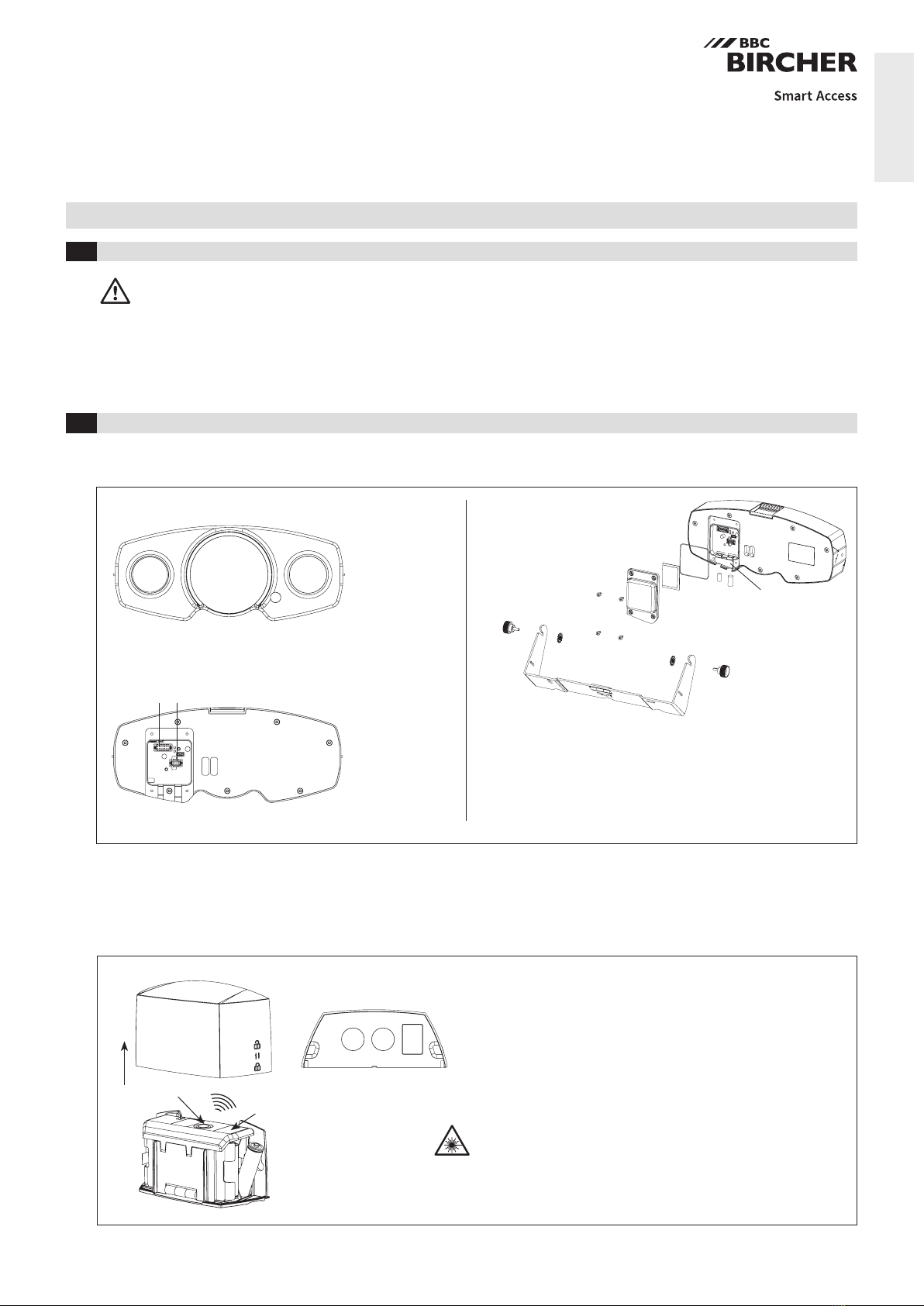
6.1 Hyperion 3D-M, Hyperion 3D-S
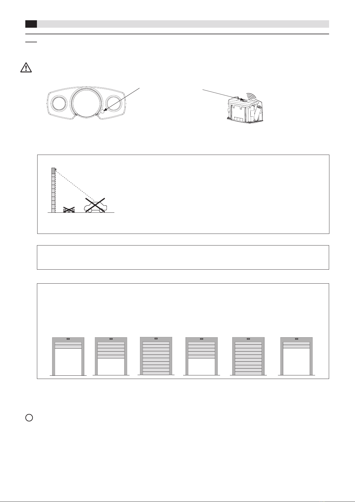
6.2 Hyperion 3D-H
Button LED Description Troubleshooting
Brief press
(< 1 s)
1x green Battery full
1x yellow Low battery Plan battery change
1x red Battery critical Change battery
Long press
(> 3 s,
LED ashes
white 1x/s)
Blue ashing Searching for master sensor
3x green Connection to master sensor
established successfully
3x red Connection to master sensor failed Repeat pairing to master sensor:
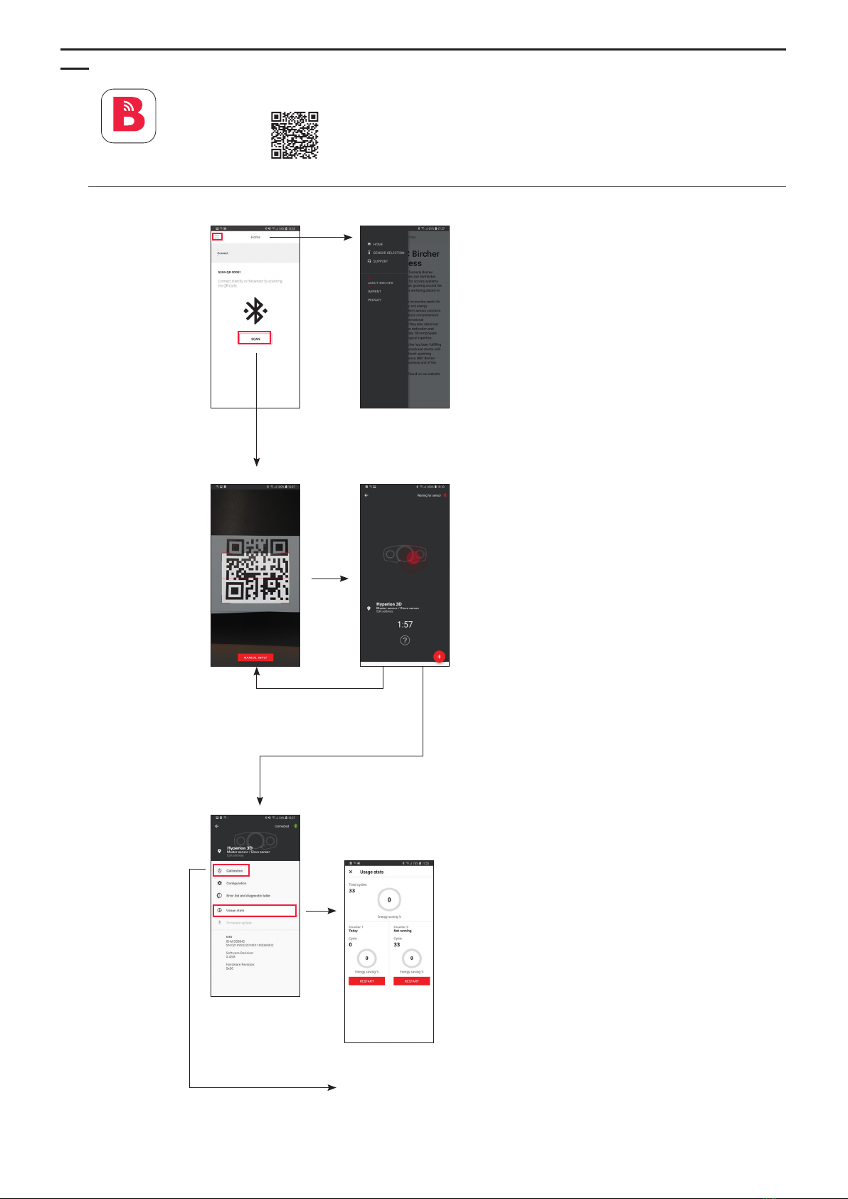
Use app Bircher SmartConnect
LED Description Troubleshooting
White Sensor powered,
ready for operation
Red Power-up The sensor will not detect objects or react to commands
Red blinking Conguration mode
(parameter change in progress)
The sensor will not detect objects.
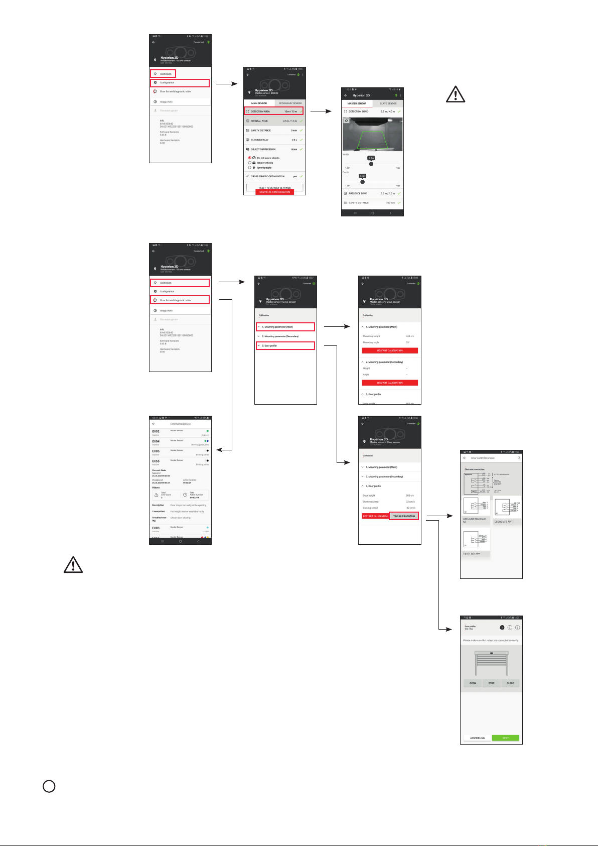
Exit access by app Bircher SmartConnect
Red/green/blue
blinking
Calibration
(1st time background teach-in)
The sensor will not detect objects or react to commands
Blue Vehicle approaching door To prevent door opening set people/vehicle parameter
Green Person approaching door To prevent door opening set people/vehicle parameter
Turquoise Unknown object approaching
door
Door might open to full height
Blue/green blinking Object in presence zone Free presence zone
White blinking Manual operation of door or
digital input (dig IN) active i.e.
sensor deactivated, see page 3
The automatic operation of the door will be ceased until the door gets
closed again by manual command.
red yellow Error Start calibration again by app Bircher SmartConnect or temporary
cutting power
red blue Error Press button on height sensor for 3s (remove cover), possibly start
calibration again
red yellow white Error Clean lenses on master sensor (slave sensor).
Check light condition > 50 lux.
red yellow blue Error Check power supply on master sensor, if error only on slave sensor ->
Check wiring from master sensor to slave sensor
red yellow yellow Error Observe temperature specication, possibly add weather hood
red yellow red Error Exchange master sensor (slave sensor)
red blue white Error Clean lenses on height sensor
red blue blue Error Check batteries on height sensor
red blue yellow Error Restart height sensor by temporary cutting power, possibly change
batteries. Check if door can be manually opened by door controller.
red blue red Error Exchange height sensor
red white blue Error Check wiring from master to slave sensor,
Exchange slave sensor
red white red Error Check opposite sensor
A list of previous errors can be found in the mobile app.

8
Made in Switzerland
BBC Bircher Smart Access, BBC Bircher AG, Wiesengasse 20, CH-8222 Beringen, www.bircher.com
8EU Declaration of Conformity
11 Contact
See attachment
10 FCC approval
9WEEE
Devices with this symbol must be treated separately during disposal. This must be done in accordance with the laws of
the respective countries for environmentally sound disposal, processing and recycling of electrical and electronic equipment.
This device meets the requirements of Part 15 of the FCC regulations and the RSS-210 standard of Industry Canada.
Warning: Changes or modications made to this device may void the FCC authorisation to operate this device.
7Technical data
Electrical data Master, slave
sensor
Height sensor
Supply voltage 24 V DC ±15% 4x AA batteries
Power consumption < 10 W (2way kit) > 2700 mAh
Outputs potential-free
max. 50 mA / 48 V
–
Digital input potential-free
max. 48 V (5 mA)
Threshold 15 V
–
System description Min. Max. Unit
Industrial door speed 0.1 1.5 m/s
height 2 10.0 m
Detection zone 1width 3 2x mounting height m
depth 2 2x mounting height m
Presence zone 1width 2 1.5x mounting height m
depth 0.1 3 m
1Objects up to 0.3 m height are ignored.
Mechanical data Master, slave
sensor
Height sensor
Dimensions
(W x D x H)
Approx.
260 x 110 x 55 mm
Approx.
135 x 55 x 75 mm
Material PC–ABS–GF20,
Aluminium
ABS
Color Black
IP protection class IP65
Operating temperature Min. –20°C
Max. +60°C
Storage temperature 0 – 40°C
Mounting height 2.5 m to 7.5 m
This manual suits for next models
4
Table of contents
Other BBC Bircher Accessories manuals