Lierda LSD4BTB-PBC1000001 User manual

LSD4BTB-PBC1000001
User Manual
Rev01 2020-12-16
User Guide

2
File revision history
Firmware
version
Document
revision date
Author
Change description
201216
L J
Initial Version

3
1 Features
An ultra-low power beacon device that supports iBeacon and Eddystone UID & URL.
2 APP communication protocol
APP sends instructions to the Beacon module through the FE61 channel. After receiving the instructions,
the module parses and executes the instructions, and returns the result of the instruction execution to the
APP through the FE62 channel. The whole process is shown in the following figure.
Figure 2 1 APP operation Beacon flow chart
2.1 Airbag structure
APP sends instructions to the Beacon module through Bluetooth. In order to facilitate module
recognition, the instructions must conform to a certain format; at the same time, the Bluetooth module will
return data to the APP in the agreed format after executing the instructions. The input frame command
format is as follows As shown in the table, the response frame command format is shown in the following
table.
Table 2 1 Input frame command format (hex)
Start
character
Command
ID
Command
length
Command
parameter
01 FC
xx
xx
xx……xx
Table 2 2 Response frame command format (hex)
Start
character
Command
ID
Command
length
Execution status
Response data

4
04 FC
xx
xx
xx
xx……xx
Start character: all command frames must start with "01 FC", and all response frames start with
"04 FC".
Command ID: The IDs of commands with different functions are unique. The following is an
enumeration and detailed explanation of all commands.
Command length: The input frame length is the number of bytes of the input frame command
parameters, and the response frame length is the sum of the execution status and the length of
the response data.
Command parameter: The command parameter of the command frame is the parameter of the
command execution.
Execution status: The execution status is the content contained in the response frame, 1 byte,
immediately after the length of the response frame, 00 means the command was successfully
received, and other non-zero means the reception/processing failed.
Response data: The response data is the data carried in the response frame. For details, see the
detailed explanation of the serial port command frame below.
Data unit: Each independent data unit with no less than 2 bytes in the instruction should be
transmitted in low-endian order, for example: The transmission order of 1000 (0x03E8) is E8 03.
2.2 Detailed instructions
ID
Command
function
Description
Drop
Electricity
Protect
Save
01
Set
Bluetooth
MAC
address
Format: 01 FC 01 06 MAC
MAC: 6-byte unsigned integer, MAC address.
Note: You need to restart the device to take effect.
Return: 04 FC 01 01 status
YES
02
Query
Bluetooth
MAC
address
Format: 01 FC 02 00
Returns: 04 FC 02 len status [MAC]
MAC: The mac address of the device.
/
03
Set device
name
Format: 01 FC 03 len Name
len: 1-byte unsigned integer, the number of bytes in the device name, range [1-20];
YES

5
Name: The name of the device, usually a visible string.
Return: 04 FC 03 01 status
04
Query
device
name
Format: 01 FC 04 00
Returns: 04 FC 04 len status [Name]
/
05
Set the
uuid
broadcast
by beacon
Format: 01 FC 05 len uuid
len: 1-byte unsigned integer, the length of uuid, fixed at 0x10. Big endian.
uuid: 16-byte unsigned integer, beacon specific uuid.
Return: 04 FC 05 01 status
YES
06
Query
beacon
broadcast
uuid
Format: 01 FC 06 00
Returns: 04 FC 06 len status [uuid]
/
07
Set the
major of
beacon
broadcast
Format: 01 FC 07 02 major
major: 2-byte unsigned integer, major beacon number, little-endian byte order.
Returns: 04 FC 07 01 state
是
08
Query the
major of
beacon
broadcast
Format: 01 FC 08 00
Returns: 04 FC 08 03 state[major]
/
09
Set the
minor of
beaco
broadcast
Format: 01 FC 09 02 minor
minor: 2-byte unsigned integer, the unique label under the major beacon number, in
little-endian byte order.
Returns: 04 FC 09 01 state
是
0A
Query the
minor of
beacon
broadcast
Format: 01 FC 0A 00
Returns: 04 FC 0A 03 state[minor]
/

6
3 Default parameters
Table 4 1 Module default parameter list
project
Default parameters
Production test
serial port baud
rate
115200bps
Broadcast
parameters
Broadcast interval: 100ms
Broadcast data: single ibeacon broadcast, if two kinds of broadcast carousels, the switching frequency is
1s.
Broadcast channel: 37, 38, 39
Scan response: switch between scan response format 1 and scan response format 2, see 5.3 for details.
The switching frequency is 1s.
Connection
parameters
Minimum connection interval -8ms
Maximum connection interval -100ms
Slave lurking-0
Connection loss monitoring timeout time 3 seconds
Transmit power
0dBm
Receive buffer
1 KB
mode
Factory mode
Battery level
detection
frequency
1 day/time
Temperature
detection
frequency
4 hour/time
Authentication
close
4 Main technical content
4.1 Introduction to Bluetooth Services and Features
S/C
Describle
UUID
Authority
Description

7
service
/
0xFE60
/
Lierda Bluetooth Low Energy Data Transmission Service
Eigenval
ues
Data M-S
0xFE61
WN/W
Command setting channel
Eigenval
ues
Data S-M
0xFE62
N
Command setting status return channel
M:Master,表示主机
S:Slave,表示从机
N:Notify
R:Read
W:Write
WN:Write no response,不回复的写入
4.2 Broadcast settings
Beacon broadcast includes three types: standard ibeacon broadcast, Eddystone UID broadcast and
Eddystone URL broadcast.
4.2.1Ibeacon Broadcast format

8
4.2.2Eddystone Broadcast format
4.2.3Standard broadcast format

9
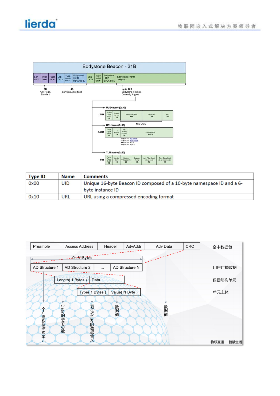
Type is a value with a common standard. You can check the meaning of the specific number on the
official website of the Bluetooth Alliance. The commonly used ones are as follows:
Incomplete 16Bit service UUID (0x02), incomplete 128Bit service UUID (0x06), device full name (0x08), device
abbreviation (0x09), vendor-defined data (0xFF), ···
When setting a custom broadcast, the broadcast data must conform to the format of the user data unit
shown in the figure above, otherwise the setting cannot be successful.
4.3 Application layer authentication processing flow
The application layer authentication mechanism is used to implement user access permission
restrictions at the application layer. This mechanism can be enabled when the standard
Bluetooth pairing encryption mechanism cannot meet the requirements.
After setting to enable application layer authentication in the encryption option (the
authentication control bit in the encryption option is set to 1), the module forces the access
user to pass the authentication mechanism to communicate normally. At the same time, the
encryption option, decryption option, and the use of random key encryption option should be
enabled to ensure the communication data.
All are transmitted in cipher text.
Figure 5 shows the authentication process after opening.
The host requests a random key, refer to the random key generation instruction (ID=0xA0);
The host receives the random key generated by the slave and encrypted (using the private
key to encrypt the random key AES128-ECB);
After the host encrypts the received random key (using the private key for AES128-ECB
encryption), it sends it back to the module through the command (ID=0xA0);
The module side verifies the random key and sends the verification result back to the
host side;
The host can send verification multiple times. After the verification is passed, the host
has the permission to access the slave. If the verification fails within 30 seconds, the module
will actively disconnect;
After the verification is passed, the module will encrypt the sent data with a random
key, and decrypt the received data with a random key.

10
4.4 Mode setting
Beacon has two modes: deployment mode and factory mode
Factory mode: In this mode, the device connection does not require an authentication process.
Deployment mode: After switching to this mode, the device needs to complete authentication within 10
seconds after being connected. The authentication method is to write the same configuration key as set in
the authentication channel to complete the authentication. If the authentication fails Pass to disconnect.
4.5 Temperature Sensor
The temperature sensor measures the mold temperature within the temperature range of the device. If the
application requires it, linear compensation can be implemented.
The main functions of TEMP are listed here:
•The temperature range is greater than or equal to the working temperature of the equipment
• The resolution is 0.25 degrees
Temperature detection is started by triggering the start task.
When the temperature measurement is completed, a DATARDY event will be generated, and the
measurement result can be read from the temperature register.
In order to achieve the measurement accuracy specified in the electrical specifications, a crystal oscillator
must be selected as the HFCLK source,
When the temperature measurement is completed, the temperature analog electronic power supply drops
to save power consumption.
TEMP only supports one operation, which means that every TEMP measurement must be done explicitly
Use start task to start.
4.6 Functional pins
Serial
number
Pin
Features
direction
instruction manual
1
P0.18
TX
output
Serial data output pin
2
P0.20
RX
Input
Serial data input pin
3
VCC
VCC
/
3.3V

11
4
GND
GND
/
Ground
5
RESET
RESET
input
Reset pin
High level: normal operation of the module
Low level: the module keeps reset
6
SWCLK
SWCLK
/
/
7
SWD
SWD
/
/
8
P0.16
INT
Input
The key pin is detected as low level at startup and enters the test
mode.
9
P0.00
LED2
output
Used to display the connection status, flashes at a frequency of
500ms after connection, and the disconnection light is off.

12
5 Warning to users
You are welcome to use the products of Lierda Technology Co., Ltd. Before using our products, please read
this warning; if you have started to use the instructions, you have read and accepted this warning.
Lierda Technology Co., Ltd. reserves the right of final interpretation and modification of all materials
provided, and subject to change without notice.
Prepared by: Lierda Technology Group Co., Ltd. Wireless Sensor Network
December 2020

FCC regulatory conformance:
This device complies with Part 15 of the FCC Rules. Operation is subject to the following two
conditions:
(1) This device may not cause harmful interference.
(2) This device must accept any interference received, including interference that may cause
undesired operation.
NOTE: This equipment has been tested and found to comply with the limits for a Class B
digital device, pursuant to part 15 of the FCC Rules. These limits are designed to
provide reasonable protection against harmful interference in a residential installation.
This equipment generates uses and can radiate radio frequency energy and, if not
installed and used in accordance with the instructions, may cause harmful interference to
radio communications. However, there is no guarantee that interference will not occur in
a particular installation. If this equipment does cause harmful interference to radio or
television reception, which can be determined by turning the equipment off and on, the
user is encouraged to try to correct the interference by one or more of the following
measures:
- Reorient or relocate the receiving antenna.
- Increase the separation between the equipment and receiver.
-Connect the equipment into an outlet on a circuit different from that to which the receiver
is connected.
-Consult the dealer or an experienced radio/TV technician for help
NOTE: The manufacturer is not responsible for any radio or TV interference caused by
unauthorized modifications to this equipment. Such modifications could void the user’s
authority to operate the equipment.
RF Exposure
This equipment complies with FCC radiation exposure limits set forth for an
uncontrolled environment. This equipment should be installed and operated with minimum
distance of 20 cm between the radiator and your body. This transmitter must not be
co-located or operating in conjunction with any other antenna or transmitter.
Table of contents
Other Lierda Security System manuals
Popular Security System manuals by other brands

Elektrotechnik Schabus
Elektrotechnik Schabus GX-C2 operating instructions

Eaton
Eaton EVT-300 Driver Instructions

HR
HR HRSBB056 Technical manual

Hamilton
Hamilton 5617-P installation manual

Interlogix
Interlogix Learn Mode Water Resistant Pendant Panic... installation instructions

iWorX
iWorX ALM2 Application guide