TABLE OF
CONTENTS
ONE YEAR
LIMITED
WARRANTY
WARNING
Warranty
Warning
Safety Precautions
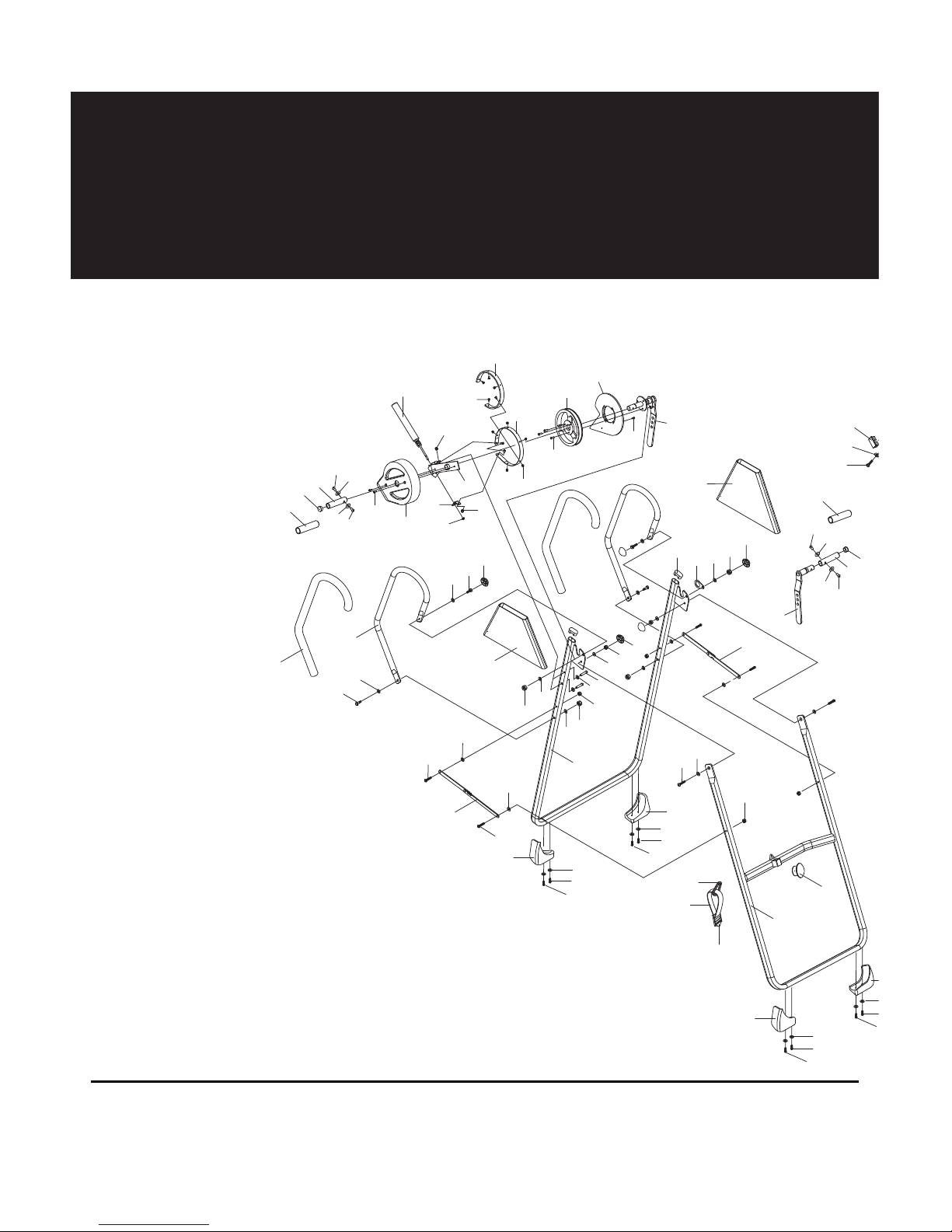
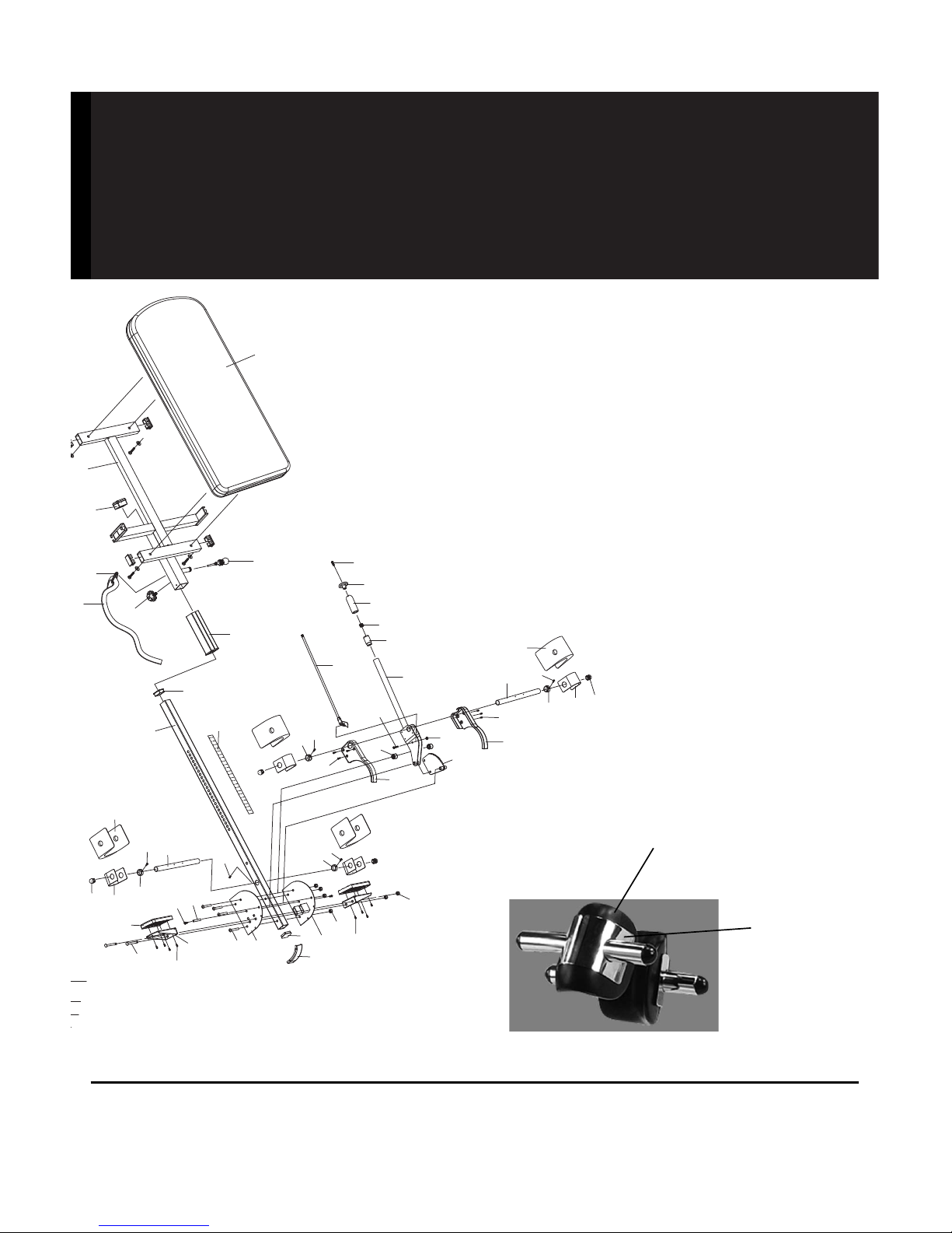
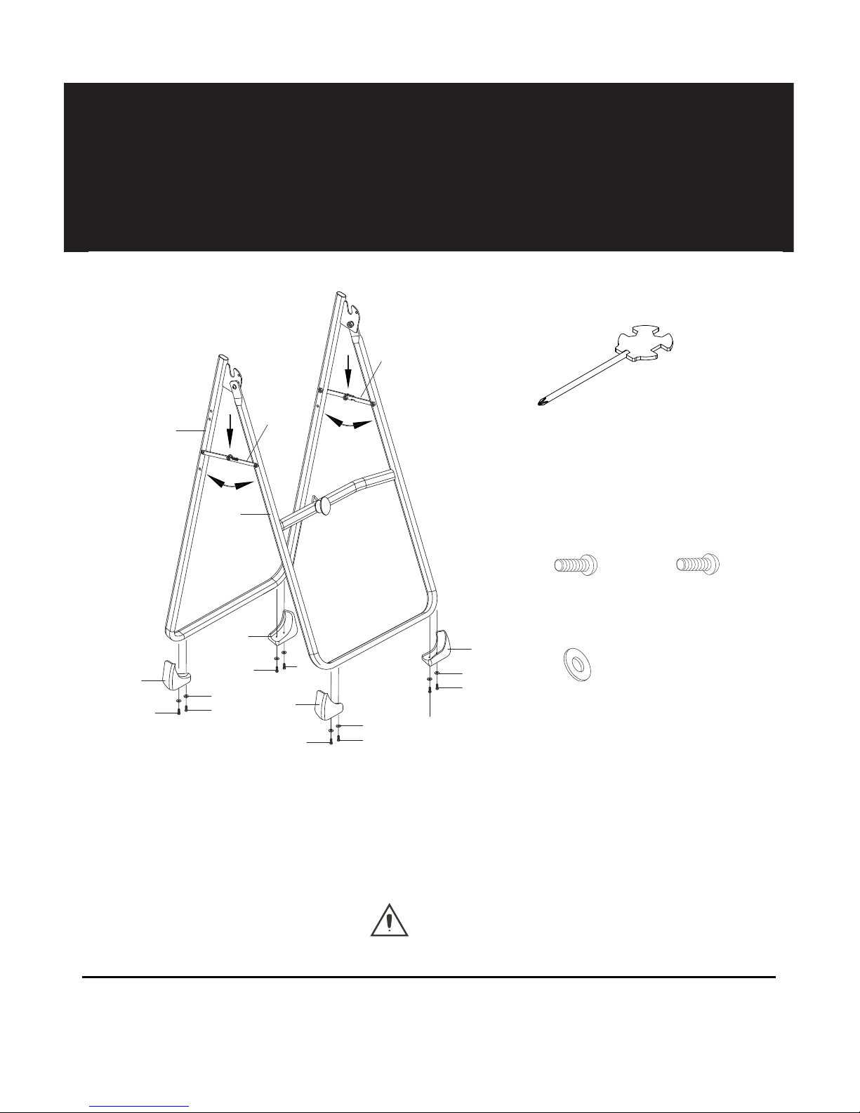
Overview Drawing
Parts List
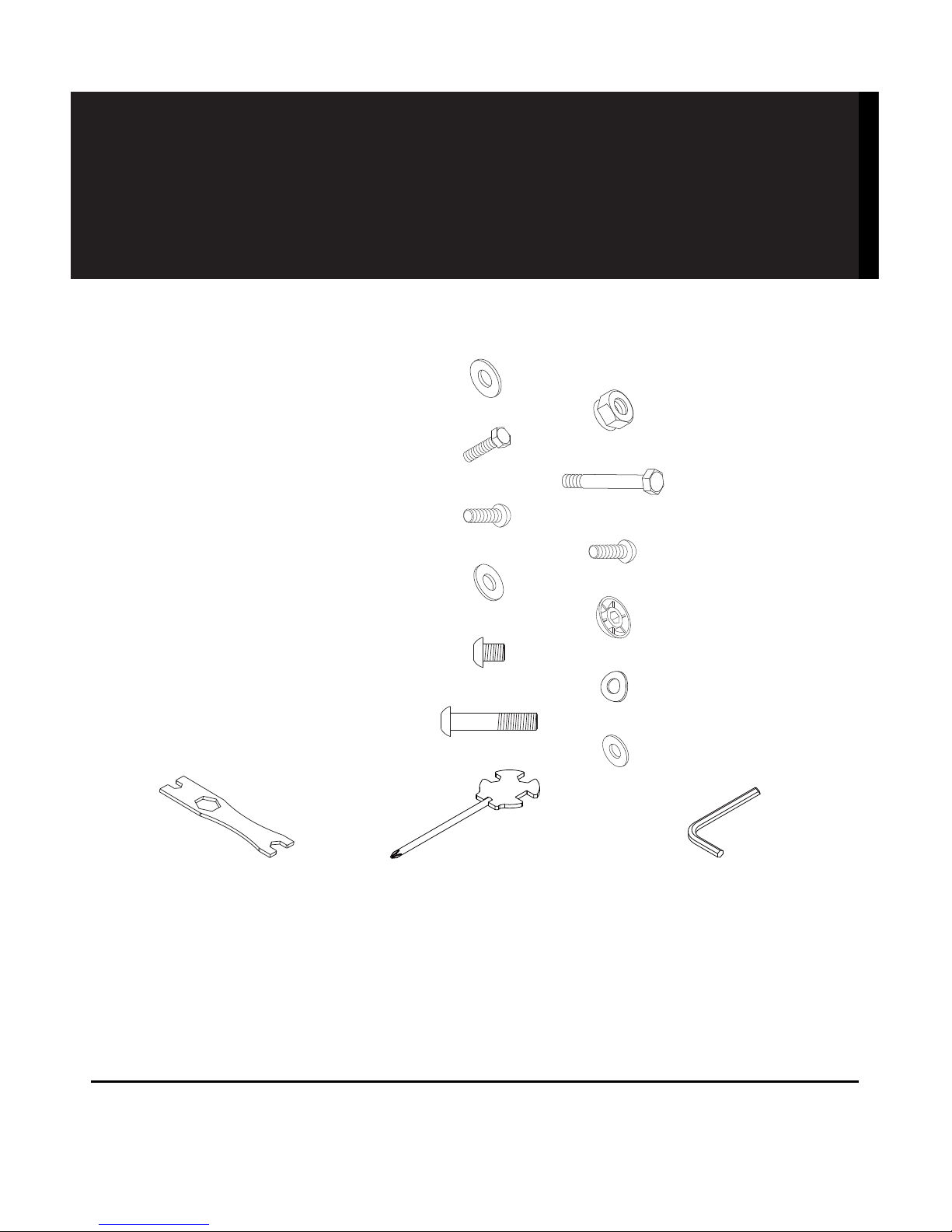
Hardware Packing List
Assembly Instructions
Safety Operating
Instructions
Operation and Adjustments
Storage
Troubleshooting
Section
Brake Handle
Adjustment
Warm Up and Cool
Down Routine
LifeGear Inc. warrants to the
original purchaser that this
product is free from defects in
material and workmanship when
used for the purpose intended,
under the conditions that it has
been installed and operated in
accordance with LifeGear’s
Owner’s Manual. LifeGear’s
obligation under this warranty is
limited to replacing or repairing,
free of charge, any parts which
may prove to be defective under
normal home use. This warranty
does not include any damage
caused by improper operation,
misuse or commercial
application.
From the date of purchase, the
frame is warranted to be free
from defects for 1 (one) year.
This warranty is offered only to
the original owner and is not
transferable. Proof of purchase
is required.
NOTE: Maximum Weight
Capacity for this product is
350lbs/160kgs.
Transport and Storage:
Humidity Between : 10% - 80%
Temperature Between : -20 c - 60 c
WARNING
Before using this product,
please consult your personal
physician for a complete
physical examination.
Frequent and strenuous
exercise should be approved
by your doctor. If any
discomfort should result from
your use of this product, stop
exercising and consult your
doctor. Proper usage of this
product is essential. Please
read your manual carefully
before exercising.
Please keep all children away
from the equipment during
use and when equipment is
unattended.
Always wear appropriate
clothing, including athletic
shoes when exercising. Do not
wear loose clothing that could
become caught during
exercise.
Make sure that all bolts and
nuts are tightened when
equipment is in use. Periodic
maintenance is required on all
exercise equipment in order to
keep it in good condition.
1