TABLEOF
CONTENTS ONEYEAR
LIMITED
WARRANTY
Warranty 1
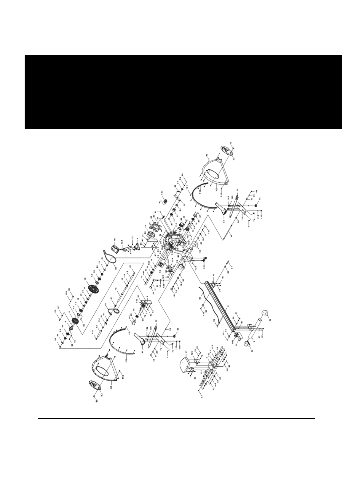
Overview Drawing 3
Parts List 4
Hardware List 7
Assembly
Instructions 9
How to Fold-Up the
Extrusion 14
How to Fold-Down
the Extrusion 15
Adjustment 16
How to Row 17
Computer Operation 18
LifeGear Inc. warrants to the
original purchaser that this prod-
uct is free from defects in mate-
rial and workmanship when
used for the purpose intended,
under the conditions that it has
been installed and operated in
accordance with LifeGear's
Owner's Manual. LifeGear's obli-
gation under this warranty is
limited to replacing or repairing,
free of charge, any parts which
may prove to be defective under
normal home use. This warranty
does not include any damage
caused by improper operation,
misuse or commercial
application.
From the date of purchase, the
frame is warranted to be free
from defects for 1(one) year. All
parts and workmanship,
including electronics and its con-
sole cases, upholstery, foam, ball
bearings, pulleys, cables, shocks,
all tension mechanisms, wheels,
pedals and hardware are to be
free from defects for 90 days,
This warranty is offerred only to
the original owner and is not
transferable. Proof of purchase is
required.
when ordering replacement parts
please have the following infor-
mation ready:
1. owner's manual
2. model number
3. description of parts
4. part number
5. date of purchase
1