Life RG1 24P Parts list manual

ISTRUZIONI E AVVERTENZE PER L’INSTALLAZIONE, L’USO E LA MANUTENZIONE.
INSTRUCTIONS AND WARNINGS FOR INSTALLATION, USE AND MAINTENANCE.
INSTRUCCIONES Y ADVERTENCIAS PARA LA INSTALACIÓN, EL USO Y EL MANTENIMIENTO.
INSTRUÇÕES E ADVERTÊNCIAS PARA A INSTALAÇÃO, USO E MANUTENÇÃO.
INSTRUKCJE I WSKAZÓWKI DOTYCZĄCE MONTAŻU, UŻYTKOWANIA I KONSERWACJI.
3DP0 750 000 - 03/2007
RG1 24P
CENTRALI DI COMANDO PER CANCELLI AD ANTA.
CONTROL UNITS FOR LEAF GATES.
UNIDADES DE CONTROL PARA CANCELAS DE UNA HOJA.
CENTRAIS DE COMANDO PARA PORTÕES DE BATENTE.
CENTRALE STERUJĄCE DO BRAM PRZESUWNYCH.

RICAMBI
SPARE PARTS
RECAMBIOS
SOBRESSALENTES
CZĘŚCI ZAMIENNE
1
1AH001
2
1AH009
!
INSTALLAZIONE STANDARD
STANDARD INSTALLATION
INSTALACIÓN ESTÁNDAR
INSTALAÇÃO STANDARD
INSTALACJA STANDARDOWA
Componenti e dispositivi di un’automazione tipo, RG1 24P.
Components and devices of a typical automation, R G1 24P.
Componentes y dispositivos de un automatismo tipo, RG1 24P.
Componentes e dispositivos de uma automação tipo, RG1 24P.
Części i urządzenia napędu typu, RG1 24P.

2 A
RG1 24P
WHITE
WHITE
WHITE
WHITE
INDICATOR LIGHT
FOTO (N.C. PROGRAMMABLE)
24 Vdc 3W max
24 Vdc 25W max
24 Vdc 15W max
COURTESY LIGHT
FLASHING
ORANGE
ORANGE
OUTPUT 24 Vdc 200 mA max
STEP
CLOSE
OPEN
STOP
L11
L10
L9
L8
L7
COMMANDS COMMON
1
2
AB
3
4
5
6
10
7
8
9F1
F2
6
7
8
9
10
11
12
13
14
15
16
17
18
19
RG58-50ohm
AERIAL
N.C.
N.C.
N.O.
N.O.
N.O.
&
5
3
%
OUTPUT 24 Vac 200 mA max
1
2
S
S
U
U
F
F
E
E
M1 M2
LN
FUSE
6AC
6AC
6AC
6AC
6AC
6AC
AGECH
MOTOR
ENCODER
LIMIT
SWITCHES
BLACK
RED
BLUE
RED
BLUE
WHITE
WHITE
GREEN
BROWN
230V
V0
V2
1
V42
MOC
ONCN
RX
V
0
V
21
V4
2
TX
6
11
18
19
1
2
14
16
12
16
1
2
3
4
5
6
15
16
24 Vdc 15w max
SPL24
24 Vdc 3w max
6
7
10
CNON MO
C
IMPIANTO ELETTRICO
ELECTRIQUE
EQUIPO ELèCTRICO
INSTALAÇÃO ELÉCTRICA
INSTALACJA ELEKTRYCZNA
N.C.
L7 L8
L9
L10
L11

Declaration of conformity
under Directive 98/37/EC, appendix II, part B (Manufacturer’s Declaration of CE Conformity)
LIFE Home Integration
Via 1 Maggio, 37
31043 FONTANELLE (TV) – Italy
declares that the following product:
RG1 24P control unit
satisfies the essential requisites established in the following directives:
• Low voltage directive 73/23/EEC and subsequent amendments,
• Electromagnetic compatibility directive 89/336/EEC and subsequent amendments,
• Radio and telecommunications equipment directive 1999/5/EC and subsequent amendments.
and satisfies the following standards:
• EN 12445:2000
Industrial, commercial and garage doors and gates – Safety in the usage of motorised doors –
testing methods
• EN 12453:
Industrial, commercial and garage doors and gates – Safety in the usage of motorised doors –
Requisites
• EN 60204-1:1997 Machinery safety – Electric equipment of the machine – Part 1: general rules.
• EN 60950 Information technology equipment - Safety - Part 1: General requisites
• ETSI EN 301489-3:2001 Electromagnetic compatibility for radio equipment and appliances.
• EN 300220-3:2000 Radio equipment and systems – short band devices – Technical characteristics and testing methods for
radio apparatus with a frequency of 25 to 1000 MHz and powers of up to 500mW.
The Manufacturer also declares that it is not permitted for the abovementioned components to be used until such time as the
system in which they are incorporated is declared conform to directive 98/37/EC.
Fontanelle ____________ Name of Signor: Faustino Lucchetta
Position: Managing Director
Signature: __________________
!

HSILGNE
2
5
5
5
5
6
7
7
8
8
8
8
8
9
9
9
10
11
11
11
11
12
12
12
12
13
13
13
13
14
14
14
14
15
15
15
15
15
16
16
17
17
17
18
18
18
18
19
19
19
19
20
20
20
20
20
20
20
20
21
21
21
21
21
21
22
22
22
22
22
22
1
RAPID INSTALLATION .
1 WIRING AND CONNECTIONS.
1.1 List of electric cables.
1.2 Setting up the electric system and connection
to the mains supply.
1.3 Control unit connections.
1.3.1 Diagram of right side of the RG1 24P board.
1.3.2 RG1 24P Control unit wiring diagram of the
lower part.
1.3.3 Indicator LEDs.
2 STARTING UP.
2.1 Description of the keyboard.
2.2 Radio control identification.
2.2.1 Step command identification.
2.2.2 Pedestrian command identification.
2.2.3 Radio control resetting.
2.2.4 Resetting all identified radio controls.
2.2.5 Identification without using the keyboard.
2.3 Initialisation.
2.3.1 Direction, travel and speed indentification.
3 ADJUSTMENTS.
3.1.1 Card initialisation.
3.1.2 Resetting travel and functions.
3.1.3 Resetting the travel.
3.2 Function modes.
3.2.1 Dead man.
3.2.2 Semi-automatic.
3.2.3 2-step automatic.
3.2.4 4-step automatic.
3.2.5 4-step automatic with stop
3.2.6 Condominium.
3.3 Functions.
3.3.1 Blackout.
3.3.2 Pre-flashing.
3.3.3 Flashing in pause.
3.3.4 Photo test.
3.3.5 Photo 1.
3.3.6 Close after photo.
3.3.7 Opening ram blow.
3.3.8 Force.
3.3.9 Pause time.
3.3.10 Courtesy light.
3.3.11 Deceleration in opening and closure.
3.3.12 Obstacle detection.
3.3.13 Pedestrian opening.
3.4 Fuses.
3.4.1 Frontal fuses.
3.4.2 Card fuse.
3.5 Preset functions F1 & F2.
4 TROUBLESHOOTING.
4.1 Malfunctions indicated on the control unit.
5 BUFFER BATTERIES (OPTIONAL).
5.1 Battery installation in the GEBOX.
6 AUTOMATION USE.
6.1 Flashing light functions.
6.2 Automation malfunction.
7 GENERAL INFORMATION.
7.1 Information on the manufacturer.
7.2 Intended use.
8 SAFETY INSTRUCTIONS AND WARNINGS.
8.1 General instructions and warnings.
8.2 Storage instructions and warnings.
9 INSTALLATION.
9.1 Instructions and warnings for installations.
10 TESTING AND TRIAL RUN.
10.1 Testing.
10.2 First usage.
11 SAFETY INSTRUCTIONS AND WARNINGS.
11.1 Instructions and warnings for use.
12 MAINTENANCE.
12.1 Maintenance instructions and warnings.
12.2 Routine maintenance.
13 DEMOLITION AND DISPOSAL.
CONTROL UNITS FOR LEAF GATES RG1 24P
Instructions and warnings for installation, use and maintenance.
MANUAL DESTINED FOR USE BY PROFESSIONAL FITTERS ONLY
Installation may only be performed by professional fitters.
INDEX

CM
N
O
230V
ON
L7
L8
L9
L10
L11
&
&
.
%3
%
2
0
/
-
/
5%4 !-/
4
5
!)
-
%
3/#
)4
!
-
/
4
5!0
/#
)
4)
3
3
!
4
5
/
(
#
!
,"
!
-
/
4
5
!0
/
#
)4 )
3
3
!
%
,
!)
.
)
-
/
$./
#
/)'
'
%
0
-
!
,
%
2
0.
)
/
)
'
'
%
0
-
!
,0!
3
5
!
/
4
/
&
0%$
5
)(
#/
$
.
!3
3
!
4
3
%
4
/
4/&
4
%)
2
!
{$
/0
,
/
#%
2
/
#
)
$
%
#
5
,!
)
3
%
4
2
%
0
!
,,
!
2!
2
5
4
2
%
0! 4 %
,
!
.
/
$%
0
!
:
2
/
&
0
/
0
-
%
4!
3
5
!
4.
%,
,
!
25
3
5
)
(#
.
)
/
4
.%
-! !
2
4)
,
)
")
3
.
%
3/
4/
-
{
!
&
&
%
4
.
%
3
%
2
0
/-
/
5!
-
/4
5
!)
-
%
3/
#
)
4
!
-
/
4
5
!0
/
#
)
4)
3
3!
4
5/
(
#
!
,
"
!
-
/4
5
!0
/
#
)
4)
3
3
!
%
,
!
)
.
)
-
/
$
.
/
#
/
)'
'
%
0
-
!
,
%
2
00
.)
/
)
'
'
%
0
-
!
,!
3
5
!
/
4/
&
0
%
$
5
)
(
#/
$
.
!
3
3
!
43
%
4
/
4
/
&
%4
%
)
2
!
{
$
/
0
,/
#
2
/
#
)
$
%#
5, !
)
3
%
4
2
%0
!
,
,
!
2!
2
5
4
2
%0!
4%
,
!
.
/
$
%
0
!
:
2
/
&
0
/
0
-
%4 !
3
5
!
4.
%
,
,
!
2!
2
5
3
5
)
(
#
.
)
/
4.
%
-
!
4
)
,
)
"
)
3
.
%
3/
4
/
-
{
!
"
X 2
2
RAPID INSTALLATION
PHASE 1
LEAF POSITIONING
a) Release the automation by opening the door.
b) Position gate at approximately 50 cm from the closure
position.
c) Close the door.
d) Manually move the gate until the automation re-locks.
a) Switch on the system’s power supply and check that
the two red LEDs flash.
b) C
heck that the lateral LEDs , L7 and L11 are switched on.
c) C
heck that the lateral LEDs L8, L9 and L10 are switched off.
PHASE 2
PHASE 3
RADIO CONTROL IDENTIFICATION ON THE STEP COMMAND (A)
a) Press , the red LED (SX) will start to flash.
b) Hold down the radio control key until the green LED
lights briefly. The green light indicates that the radio
control has been identified.
c) Wait for 15 secs or press twice to exit.
UNBLOCKING

HSILGNE
3
&
!"
&
5/-/0
2
%3%
.4
%3
%
-)!54
/-!
4
)#
/
!54
/-!
4
)#
/0
!33)
"
,!#
(/
54
!54
/-!4) #/ 0
!3
3
)
#
/.$/-).
)!
,%
0
2
%
,!-0
%
'
'
)/ ,!-0%
'')/
).
0!53
!
&
/4
/
#()5$%
0
!33!.$/
&
/4/4
%
34
#
/,0
/${!2
)%
4
%
,5#%
$)#
/2
4
%
3
)!
2
!,,!0%
2
4
52
!
!0%
2
4
0
%
$/.!,%
&
/2:!
4%-0
/0! 5 3!
2
!,,%.4
!-%
.4/).
#
()5
352!
3%.3)"),)4
!{-/4
/
OFF
230V
OFF
ON
230V
ON
&
&
5/-/0
2%3%.4
%3%-)!54
/-!
4
)#
/
!54
/-!4)#
/0
!3
3
)
"
,!#
(/
54
!54
/-!
4
)#
/0
!33)
#
/.$/-).
)!,%
0
2
%
,!-0%'
'
)/ ,!-0
%
'
'
)/
).
0!53
!
&
/4/
#
()5
$%
0
!3
3!.$/
&
/4
/4%3
4
#/,0
/${!2)%4 %
,5#
%$)
#/2
4
%
3
)!
2
!,,!0%2
452
!
!0
%
2
4
0
%
$/.!,%
&
/2
:!
4
%- 0
/0
!53
!
2
!,,%
.4
!-%
.4/).
#()5
3
52
!
3%.3
)"
),
)4!{-/4
/
!"
"
CLOSE
"
OPEN
"
#
a) Switch off power supply.
b) Simultaneously press and hold down and and
switch on the power supply to the system to light the
first LED.
c) Release keys and , the two red LEDs will now
flash.
PHASE 4
CARD INITIALISATION
a) Press and hold down the radio control key (A). The
gate will close slowly.
If the gate opens, release and then re-press the key:
the gate will move in the opposite direction.
Hold the key down until the gate reaches the closure
stop plate.
b) Ensure that when the gate is closed, one of the two
red LEDs (closure stop plate) lights and the other
continues to flash.
PHASE 5
CLOSURE STOP PLATE IDENTIFICATION
a) Press and hold down the radio control key (A): the
gate will open.
b) When it reaches the opening stop plate, ensure that
one red led (opening stop plate) is lit and the other
one continues to flash.
PHASE 6
OPENING STOP PLATE IDENTIFICATION:

"
CLOSE
N
O
230V
ON
FFO
230V
OFF
&
&
%
4
.%3
%
20
/
-/
5!
-
/
4
5
!
)-
%
3/
#
)
4
!
-
/4
5
!0
/
#
)
4)
3
3!
4
5
/
(
#!
,
"
!
-
/
4
5
!0
/
#
)
4)
3
3
!
%,!)
.
)
-
/
$
.
/
#
/
)
''%0-
!,
%
2
00.)
/
)
'
'
%
0
-
!, !
3
5
!
/
4
/
&
0
%
$
5
)
(
#/
$
.
!
3
3!
43
%
4
/
4
/
&
%
4
%
)
2
!{$
/
0
,
/
#
2
/
#
)$
%
#5
,!
)
3
%
4
2
%0
!
,
,!2 !
2
5
4
2
%
0
!
4%
,
!
.
/
$
%
0
!
:
2
/
&
0
/
0-%
4!
3
5
!
4
.
%
,
,
!
2!2
5
3
5)(
#
.
)
/
4
.
%-!
4
)
,
)
"
)
3
.
%3 /4/
-
{!
4
a) Press and release radio control key (A): the gate closes
at a normal speed.
b) Once it is closed, ensure that the two green LEDs flash
and that one red led (closure stop plate) flashes.
PHASE 7
SPEED IDENTIFICATION
a) Switch off the system’s power supply.
b) Press and switch on the system’s power supply
until all four LEDs light.
RESETTING THE CONTROL UNIT
The automation is now programmed.
The control unit is in SEMIAUTOMATIC mode.
If you are dissatisfied with the result obtained, reset the control unit and repeat procedure from start.

HSILGNE
1 WIRING AND CONNECTIONS
• Before commencing wiring and connection work, read the SAFETY INSTRUCTIONS AND WARNINGS and INSTALLATION INSTRUCTIONS
AND WARNINGS Chaps carefully.
• All wiring and connection operations must be carried out with the control unit disconnected from the electricity supply. If the disconnection
device is not in view, display a sign reading: “ATTENTION: MAINTENANCE WORK IN PROGRESS”.
1.1 List of electric cables
The cables needed may vary depending on the installation and type and quantity of devices installed.
The cables used in the installation must be IEC 60335 compliant.
ATTENTION: the cables used must be suited to the type of installation. It is the Fitter’s
responsibility to choose appropriate material.
•
The power cable may be no lighter than 60245 IEC 57 ( HO5RN-F).
• Inside the power cable, one wire must be yellow and green.
• The power cable coating must be composed of a polychloroprene sheath.
• All wires must be unsheathed as little as possible (6mm at the most) and as close as possible
to the connection terminals, in order to prevent accidental contact with live parts in the event
that cables disconnect from the terminals.
• Do not pre-seal cables to be fastened to the terminals using screws.
• If it is possible that wires subject to voltage higher than 50 Volt RMS and very low voltage
safety wires may come into contact with one another, wires with voltage higher than 50 volt
RMS must be insulated with a sheath; or the very low voltage safety wire must have an
insulating sheath at least 1mm thick
• All external connection cables must not be of the flat twin tinsel cord type.
• A power cable fastening device must be provided. Assemble the power cable so that if it comes out of its fastening device, the neutral and live wires
are taut before the earth wire.
1.2 Setting up the electric system and connection to the mains supply
This manual does not describe how the electrics system should be prepared for connection to the mains. It does, however, give the following warnings:
• The electricity supply line must be installed and connected by an authorised electrician or professional fitter.
• The electricity supply must be adequately protected against short circuits and static discharge.
• The power supply network must contain an omnipolar disconnection device with an opening distance of the contacts equal or greater than 3.5 mm
that assures the complete disconnection of the power supply.
1.3 Control unit connections
Fitters must make the connections of the 230 Vac 50 Hz electricity supply, and the various automation devices.
Connections between the control unit, motor, encoder and transformer have already been performed by the Manufacturer.
• Once the connections to the control unit have been made, the Fitter must use bands to join adjacent wires into groups of 2, 3 or 4 in order to prevent
them coming away from the terminal board: bands must be attached as close as possible to the terminals, no more than 10mm away, taking care
not to damage wire insulation. No cable may remain unpaired.
• The bands are only for unsheathed cables (sheathed cables are held in place by the sheath).
• Pay careful attention not to pair wires with voltages higher than 50 Volt RMD with lower voltage wires.
• The wiring performed internally by the manufacturer is already equipped with clamping bands.
ATTENTION: for safety reasons, it is essential to earth the motor.
5
Pos. Type of cable
%LECTRICITYSUPPLYLINE
&LASHINGLIGHT
2ADIOAERIAL
4X0HOTO
2X0HOTO
3ELECTOR
%NCODER
3CREENED2'
CABLE
CABLE
CABLE
CABLE
CABLE
CABLE
CABLE
CABLE
Connection

Terminals
Description (VEDI SCHEMA ELETTRICO A Pag. 2A)
AERIAL: aerial sheath input Use a RG58- 50ohm cable
AERIAL: aerial cable input
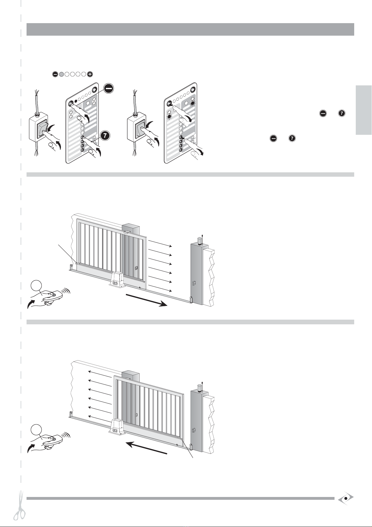
1
2
6
6 - 8
6 - 7
COMMAND AND PHOTOCELL COMMON: for stop, open, close, step, photo and +12V inputs.
OPEN: NO input, commands gate opening.
16 + FLASHING OR COURTESY LIGHT POWER SUPPLY COMMON.
6 - 9 CLOSE: NO input, commands gate closure.
STOP*: programmable NC input, commands gate stoppage.
Can be connected to safety devices such as an emergency stop button.
When the command is released automatic closure never occurs and a new movement command must be given.
Leave jumpered if no device is envisaged.
11 PHOTO*: NC input for photocells or safety devices. Does not intervene during gate opening; during closure causes reversal of gate
motion until open
Leave jumpered if no device is envisaged
14 - 16 FLASHING LIGHT: 24 Vdc 25W max output for connecting a SPLENDOR SPL24 flashing light characterised by three flashing modes:
1) slow during door opening; 2) fast (flashing times halved) during closure. 3) three flashes and a pause to indicate a fault state or travel
identification.
COURTESY LIGHT: 24 Vdc 40W max. output for connecting a courtesy light that switches on at the start of each movement (openingor
closure) and is characterised by an adjustable on time.
12 - 16 INDICATOR LIGHT: 24Vac 3W max output, for connecting an indicator light that copies the function of the flashing light during movement
and that remains on when the gate is open.
15 - 16
6 - 10 STEP: NO input, commands gate movement according to the following cycles:
SEMI-AUTOMATIC MODE: Open, stop, close, stop.
4-STEP MODE Open, pause, close, pause.
2-STEP MODE Open – close.
CONDOMINIUM MODE: Open.
30 V ac OUTLET: power supply for various devices, 200 mA max.
16 +
17 -
24 V ac OUTLET: power supply for various devices, 200 mA max.
18
19
* 6-76-11 are NC inputs that can be set as photo, photo1, photo2, stop, and pause.
Photo: NC input for photocells or safety devices. Does not intervene during gate opening; during gate closure it causes a brief reversal of motion until open.
Photo1: NC input for photocells or safety devices. It causes the stoppage of the gate both in opening than in closure. The motion restart in opening
when photocell or safety deciveces is disengaged.
Photo2: NC input for photocells or safety devices. Does not intervene during gate closure; during gate opening it causes a brief reversal of motion,
followed by stoppage until a new command is given.
Stop: commands gate stoppage. When the command is released, automatic closure never occurs and a new movement command must be given.
Pause: Causes a pause in the door’s motion. If automatic closure at the end of the pause time is active, it causes re-closure, otherwise it waits fora new command.
Pedestrian: the command causes partial and adjustable opening of a single leaf. Can be given using a remote control or the terminal board. Obtained
from the terminal board by jumpering terminal 8 OPEN with terminal 9 CLOSE, this jumper then connects with a switch to terminal 6 COMMON.
When given from the terminal board, the PEDESTRIAN command excludes the OPEN and CLOSE commands.
N.C. = normally closed contact – NO = normally open contact.
6
1.3.1 Diagram of right side of the RG1 24P board

HSILGNE
1.3.2 RG1 24P Control unit wiring diagram of the lower part
ATTENTION: the connections pre-wired by the manufacturer may not be altered under any circumstances.
1.3.3 Indicator LEDs
There is a row of 6 LEDs on the right hand side of the board, under the terminals. These LEDs are lit when the corresponding signal is present. For
the NC inputs, stop, photo and photo1, the corresponding LEDs L7, L8 and L12 are normally lit; for the NO inputs close, open and step, the corre-
sponding LEDS L8, L9, L10 and L11 are off. These LEDs therefore indicate any malfunction of the connected devices.
N.C. jumpered input Layout tipical installation photocells
Terminals
Description (VEDI SCHEMA ELETTRICO A Pag. 2A)
LTRANSFORMER POWER SUPPLY 230Vac 50Hz
WHITE CABLE
ORANGE CABLE
ORANGE CABLE
20
WHITE CABLE
GEAR MOTOR POWER SUPPLY 24Vac.
Gear motor release switch.
21
22
23
24
0
16
0
24 AGECH
N
ELECTRONICS POWER SUPPLY 16 Vac
0,5 A
CAVO ROSSO
CAVO NERO
MOTOR POWER SUPPLY: 24 Vdc
CAVO BLU
FINECORSA 2
26
25
FINECORSA 1
-
32
31
+
COMUNE
STOP PLATE
27
CAVO VERDE
CAVO BIANCO
CAVO BLU
CAVO ROSSO
CAVO MARRONE
+
29
28
SEGNALE
-
ENCODER
30
7
L7 L8
L9
L10
L11

1
2
AB
3
4
5
6
10
7
8
9F1
F2
SX DX
&
&
%
4.
%
3
%
2
0
/
-
/
5!-
/
4
5!
)
-%
3/
#
)
4
!
-
/4
5
!0
/
#)
4)
3
3
!
4
5
/
(
#
!
,
"
!
-
/
4
5
!0
/
#
)4 )
3
3
!
%
,
!
)
.
)
-
/$.
/#
/)''%0
-
!
,%
2
00
.
)
/
)
'
'
%0-
!
,!
3
5
!
/
4/&
0%$5
)
(
#/
$
.
!
3
3
!
4
3%
4
/
4
/
&
%
4
%
)2
!
{
$
/
0
,
/
#
2/
#
)
$
%
#5
,!
)
3%
4
2%
0
!
,
,
!
2!25
4
2
%
0
!
4%
,
!
.
/$
%
0
!
:
2
/
&
0
/
0
-%
4!
3
5
!
4
.
%,
,
!
2!
2
5
3
5
)
(
#
.
)
/
4
.
%-
!
4
)
,
)"
)
3
.%
3/
4/
-
{
!
"
&
&
%4
.
%
3
%
2
0
/
-/
5!
-/
4
5
!
)-
%
3/
#
)
4
!
-
/
4
5
!0
/
#
)
4)3
3
!
4
5
/
(
#!
,
"
!
-
/
4
5
!0
/
#)
4)3
3
!
%
,
!
)
.
)
-
/
$
.
/
#
/
)'
'
%
0
-
!,%
2
00
.
)
/
)
'
'
%
0
-
!
,!
3
5
!
/
4
/&
0
%
$
5
)
(
#/
$.
!
3
3!
43%
4
/
4
/&
%
4
%
)
2
!
{$
/
0
,
/
#
2
/
#
)
$
%
#
5
,!
)
3%
4
2
%
0
!
,
,
!2!
2
54
2
%
0
!
4%
,
!.
/
$
%0
!:
2
/
&
0
/
0
-%4 !
3
5
!
4
.
%
,
,!2 !
2
5
3
5
)
(
#
.
)
/
4
.
%
-!
4
)
,)
"
)
3
.
%
3/
4
/
-
{
!
&
&
%
4.
%
3
%
2
0
/
-
/
5!
-
/
4
5!
)-
%
3/
#
)4
!
-
/
4
5
!0
/
#
)
4)
3
3
!
4
5
/
(#!
,
"
!
-/
4
5
!0
/
#
)4)
3
3
!
%,
!
)
.
)
-/$
./
#
/
)
'
'
%
0
-!
,
%
2
00
.
)
/
)
'
'
%
0
-
!, !
3
5
!
/
4
/
&
0
%
$5
)
(
#/
$
.
!3
3!
43
%
4
/4
/
&
%4%
)
2
!{
$
/0
,
/
#
2
/
#
)$
%#
5
,!
)
3
%
4
2%
0
!
,
,
!
2!
25
4
2
%0
!
4%
,
!
.
/
$
%
0
!
:
2
/
&
0
/0-
%4 !
3
5
!
4
.
%
,
,!
2!
2
5
3
5
)
(
#
.
)
/4
.
%
-
!
4
),
)
"
)
3
.
%
3/4
/
-
{!
X1
&
&
%4
.%3
%
2
0
/
-
/5 !-
/
4
5!
)
-
%
3/
#
)
4
!
-
/
45!0
/
#
)4 )
3
3
!
4
5
/
(
#
!
,
"
!-/4
5
!0
/
#
)4 )
3
3
!
%
,
!
)
.
)-
/
$
.
/#
/
)''%
0
-!,%
20 0
.
)
/
)
''
%
0-
!
,!
35
!
/
4
/
&
0
%
$
5
)
(
#/
$.
!
3
3
!
4
3
%4
/4
/
&
%
4
%)2
!{
$
/0
,
/
#
2
/
#
)$
%
#5, !)
3
%
4
2%
0
!
,,
!
2!2
5
4
2
%
0
!
4%
,!
.
/
$
%0
!:
2/
&
0
/
0
-
%
4!
3
5
!
4
.
%
,
,
!
2!
2
5
35
)
(
#
.
)
/
4
.
%-
!
4
)
,
)
"
)
3
.
%3 /
4/
-
{
!
X 2
&
&
%
4
.
%
3
%
2
0
/
-
/
5!
-
/
4
5
!
)
-
%3 /
#
)4
!
-
/
4
5
!0
/
#
)
4)
3
3!
4
5
/
(
#
!
,
"
!
-
/
4
5
!0
/
#
)4 )3
3
!
%
,
!
)
.
)
-
/
$
.
/#
/
)
'
'
%0
-
!
,
%
2
00
.
)
/
)
'
'
%
0
-
!
,!
3
5!
/
4
/&
0
%
$
5)
(
#/
$
.
!
33
!
4
3
%
4
/
4
/
&
%4
%)
2
!
{
$
/
0
,
/
#
2
/
#
)
$
%
#
5
,!
)
3
%
4
2
%
0
!
,
,
!
2!
2
5
4
2
%
0
!
4%
,
!
.
/
$
%
0
!
:
2
/&
0
/
0
-
%
4!
3
5
!
4
.
%
,,
!
2!
2
5
3
5
)
(
#
.
)
/
4
.%
-
!
4
)
,
)
"
)
3
.
%
3/
4
/-
{
!
"
&
&
%4
.
%
3
%
2
0
/
-
/
5!
-
/
4
5
!
)
-
%
3/
#
)
4
!
-/
4
5! 0
/
#
)
4)
3
3
!
4
5
/
(
#
!
,
"
!
-
/
4
5
!0
/
#
)
4)
3
3
!
%
,
!
)
.
)
-
/
$
.
/
#
/
)
'
'
%0
-
!
,
%
2
00
.
)/
)
'
'
%
0
-
!
,!3
5
!
/4
/
&
0
%
$
5
)
(
#/
$
.!
3
3!
4
3
%
4
/
4
/
&
%
4
%
)
2
!
{
$
/
0
,
/
#
2
/
#
)
$
%
#
5, !
)
3
%
4
2%
0
!
,
,
!
2!
2
5
4
2%
0!
4%,
!.
/
$
%
0
!
:
2
/
&
0
/
0
-
%
4!
3
5!
4
.
%
,
,
!
2!2
5
3
5
)
(
#
.
)
/
4
.
%-
!
4
)
,
)
"
)
3
.
%
3/
4
/
-
{!
&
&
%
4
.
%
3
%
2
0
/
-
/
5!
-
/
4
5!
)
-
%
3/
#
)
4
!
-/
45!0
/
#
)
4)
3
3
!
4
5
/(#
!
,
"
!
-
/
45
!0
/#
)
4)3
3
!
%
,
!
)
.
)
-/
$.
/
#
/
)''
%
0
-
!
,
%
2
00
.
)
/
)
'
'
%0
-
!
,!3
5
!
/
4
/
&
0
%$
5
)
(
#/$
.
!
3
3
!
4
3
%
4
/
4
/&
%
4
%
)
2
!
{$
/0
,
/
#
2/
#
)$
%#5
,!
)
3
%
4
2
%
0
!
,
,
!2 !
2
5
4
2
%
0
!
4%
,
!
.
/
$
%0
!
:
2/
&
0
/
0
-
%
4!
3
5
!
4
.
%
,
,
!
2!
2
5
3
5
)
(
#
.
)/
4
.
%-
!
4
)
,
)"
)
3
.
%3 /
4
/
-
{!
X2
&
&
%
4
.
%3
%
2
0
/
-
/
5!
-
/
4
5
!
)
-
%3 /
#
)
4
!-
/
4
5! 0
/
#
)
4)
3
3
!
4
5
/
(
#
!
,"
!-
/
4
5
!0
/
#
)4 )
3
3!
%
,
!).
)-
/
$
./
#
/
)
'
'
%0-
!
,
%
20 0
.
)
/
)
'
'
%
0
-
!, !
3
5!
/
4
/
&
0
%
$
5)
(
#/
$
.
!
3
3
!
4
3
%
4/
4
/
&
%
4
%
)
2
!
{
$
/
0
,
/
#
2
/
#
)
$
%#
5
,!
)3
%
4
2
%
0
!
,
,
!
2!
2
5
4
2
%
0!
4%
,
!
.
/
$
%
0
!
:2
/
&
0/
0-
%
4!
3
5
!
4
.
%
,,
!
2!
2
5
35
)
(
#
.
)
/
4
.
%
-
!
4
)
,)
"
)3
.
%
3/
4
/
-
{
!
X 2
8
2 STARTING UP
2.1 Description of the keyboard
The keyboard on the control unit makes it possible to set all the functions necessary for a safe and
controlled functioning of the automation.
• It is constituted by a membrane keyboard divided by a central column of keys, (from to
) into two vertical areas: the right-hand keyboard (black/blue) and the left-hand keyboard
( grey/yellow). Each vertical keyboard manages and memorises certain operation parameters.
• The selection of the right or left keyboard takes place by pressing one of the two buttons with
the symbol (A) or (B): the button Aactivates the TERMINAL STRIP (SX), and button B
selects the TERMINAL STRIP (DX).
• Keyboard de-selection takes place automatically after a certain interval of time from the last
key pressed with the exception of the FORCE function, which remains active until another
function is selected.
• When the LEDs (DX) and (SX) flash alternately, it is possible to set parameters from to .
• The buttons and are used to vary the values or parameters.
• The horizontal row of red LEDs from 1 to 5 indicates the value set for a given
parameter: the more LEDs lit, the higher the parameter value. They are also used as a status
indicator for certain parameters.
• The lateral red LEDs indicate a non-set parameter status if they flash: , and they indicate
the detection of the stop plate signal (right or left) when they are lit: .
• the lateral green LEDs indicate a parameters set or correct function status according to the
keyboard selected.
2.2 Radio control identification
The control unit is fitted with a built-in radio receiver with a 1000-code memory and 2 channels with a 433.92 MHz frequency with LIFE Rolling
Code and Auto code encoding.
2.2.1 STEP command identification
1) Press , the red LED (SX) will flash slowly and the
SPLENDOR flashing light (if present) will emit a single flash.
2) Press the key (A) on the radio control(s) that one wants
to identify and hold down until the green LED (SX) and
the SPLENDOR flashing light light briefly.
3) To exit identification, wait approximately 15 seconds until
the two red LEDs flash if the travel has not yet been
identified, or the two green LEDs flash when the travel
has already been identified.
4) It is possible to exit without waiting the automatic exit
time by pressing twice.
2.2.2 PEDESTRIAN command identification
1) Press , the red LED (DX) will flash slowly and the
SPLENDOR flashing light (if present) will emit double flashes.
2) Press the key (A) of the radio control(s) that one wants
to identify and hold down until the green LED (DX) and
the SPLENDOR flashing light light briefly.
3) To exit identification, wait approximately 15 seconds
until the two red LEDs flash if the travel has not yet
been identified, or the two green LEDs flash when the
travel has already been identified.
4) It is possible to exit without waiting the automatic exit
time by pressing twice.

HSILGNE
&
&
%
4
.
%3%
2
0
/
-
/
5!
-
/
4
5!
)
-
%
3/#
)
4
!
-
/
4
5
!0
/#
)
4)
3
3!
4
5
/
(
#
!
,
"
!-
/
4
5
!0
/
#
)
4)
3
3!
%
,
!
)
.
)
-
/
$
.
/
#
/)
'
'
%
0-
!
,
%
20 0
.
)
/
)
'
'
%0
-
!
,!
3
5
!
/
4
/
&
0
%
$
5
)
(
#/
$
.
!
3
3
!
4
3
%
4
/
4
/
&
%
4
%)
2
!
{
$
/
0
,
/
#
2
/
#
)
$
%
#
5
,!
)3
%4
2%
0
!
,
,
!
2!
2
5
4
2
%
0
!
4%
,!
.
/
$
%
0
!
:
2
/
&
0
/
0
-
%
4!
3
5
!
4
.
%
,
,
!
2!
2
5
3
5
)
(
#
.)
/4
.
%-
!
4
)
,)
")
3
.
%
3/4
/-
{
!
&
&
%
4
.
%
3
%
2
0
/
-
/
5!
-
/45
!
)
-
%
3/
#
)
4
!
-
/
4
5
!0
/
#
)
4)
33
!
45
/
(
#
!,
"
!
-
/
4
5! 0
/
#
)4 )
3
3
!
%
,
!)
.
)
-
/
$
.
/
#
/
)
'
'%
0
-!
,
%2
00
.
)
/
)
'
'
%
0
-
!, !
3
5
!
/
4
/
&
0
%
$
5
)(
#/
$
.
!
3
3
!
4
3
%
4
/4
/
&
%
4%)
2
!{$
/0,
/
#
2
/
#
)$
%#5
,!
)3
%
4
2
%
0
!
,
,
!
2!
2
5
4
2
%
0!
4%
,
!
.
/$
%
0
!
:
2
/&
0
/
0
-%
4!3
5!
4
.
%
,
,
!
2!
2
5
3
5
)
(#
.
)
/
4
.
%
-
!
4
),
)
")
3
.
%
3/
4
/-
{
!
&
&
%
4
.
%
3%2
0
/
-
/
5!
-
/
4
5
!
)
-
%
3/
#
)
4
!
-
/
4
5! 0
/#
)
4)
3
3
!
4
5
/(
#
!
,"
!
-
/
45
!0
/
#
)
4)
3
3
!
%
,
!
)
.
)
-
/
$.
/
#
/
)
'
'%
0
-!,
%
2
00
.)
/
)
''
%
0-
!
,!
3
5
!
/
4
/
&
0
%
$
5
)
(# /
$.
!
33!
4
3
%
4
/
4
/
&
%
4%
)
2
!
{
$
/
0
,
/
#
2
/
#
)
$
%
#
5
,!
)
3
%4
2
%
0
!
,
,
!
2!
2
5
4
2
%
0
!
4%
,
!.
/
$
%0
!
:
2
/&
0
/
0-
%
4!
3
5
!
4
.
%
,
,
!
2!
2
5
35
)
(
#
.
)
/
4
.
%-
!
4)
,
)
"
)
3
.%3 /
4
/
-
{
!
&
&
%
4
.
%
3
%2
0
/
-
/
5!
-
/
45
!
)
-
%
3/
#
)
4
!
-/
4
5
!0
/
#
)
4)
3
3
!
4
5
/
(
#
!
,
"
!
-/
45
!0
/
#
)
4)
3
3
!
%
,
!).)
-
/
$.
/
#
/
)
'
'
%
0
-
!
,
%
2
00
.
)
/
)
''
%0
-!
,!3
5
!
/
4
/
&
0%
$
5
)
(
#/
$
.
!
3
3
!
4
3%4
/
4
/
&
%
4
%)
2
!
{
$
/
0
,
/#
2
/
#
)
$
%#5
,!)
3
%
4
2%
0
!
,
,!
2!
2
5
4
2
%
0
!
4%
,
!
.
/
$%
0
!
:
2
/
&
0
/
0
-
%
4!
35!
4.
%
,
,!
2!
2
5
35)
(
#
.)
/
4
.
%-!
4
)
,
)
")
3.%
3/
4
/
-
{
!
X 2
"
X 1
X3
9
&
&
%
4
.
%
3
%
2
0
/
-
/
5!
-
/
4
5
!
)
-
%
3/
#
)
4
!
-
/
4
5
!0
/
#
)
4)
3
3
!
4
5
/
(
#
!
,
"
!
-
/
4
5
!0
/
#
)
4)
3
3
!
%
,
!
)
.
)
-
/$
.
/
#
/
)
'
'
%
0-
!
,
%
2
00
.
)
/
)
'
'
%
0
-
!
,!
3
5
!
/
4
/
&
0
%
$
5
)
(
#/
$
.
!
3
3
!
4
3
%
4
/
4
/
&
%
4
%
)
2
!
{
$
/
0
,
/
#
2
/
#
)
$
%
#
5
,!
)
3
%
4
2
%
0
!
,
,
!
2!
2
5
4
2
%
0
!
4%
,
!
.
/
$
%
0
!
:
2
/
&
0
/
0
-
%
4!
3
5
!
4
.
%,
,
!
2!
2
5
3
5
)
(#
.)
/
4
.
%
-
!
4
)
,
)
"
)
3
.
%
3/
4
/
-
{
!
&
&
%
4
.
%
3
%
2
0
/
-/
5!
-
/
4
5
!
)
-
%
3/
#
)
4
!
-
/
4
5
!0
/
#
)
4)
3
3
!
4
5
/
(
#
!
,
"
!
-
/
4
5
!0
/
#
)
4)
3
3
!
%
,
!
)
.
)
-
/
$
.
/
#
/
)
'
'
%
0
-
!
,
%
2
00
.)
/
)
'
'
%
0
-
!, !
3
5
!
/
4
/
&
0
%
$
5
)
(
#/
$
.
!
3
3
!
4
3
%
4
/
4
/
&
%
4
%)
2
!
{
$
/
0
,
/
#
2
/
#
)
$
%
#
5
,!
)
3
%
4
2
%
0
!
,
,
!
2!
2
5
4
2
%
0
!
4%
,
!
./
$
%
0
!
:
2
/
&
0
/
0
-
%
4!
3
5
!
4
.
%
,
,
!
2!
2
5
3
5
)
(
#
.
)
/
4
.
%
-
!
4
)
,
)
"
)
3
.
%
3/
4
/
-
{
!
X1
&
&
%
4
.
%
3
%
2
0
/
-
/
5!
-
/
4
5
!
)
-
%
3/
#
)
4
!
-/
4
5
!0
/
#
)
4)
3
3
!
4
5
/
(
#
!
,
"
!
-
/
4
5
!0
/
#
)
4)
3
3
!
%
,
!
)
.
)
-
/
$
.
/
#
/
)
'
'
%
0
-
!
,
%
2
00
.
)
/
)
'
'
%
0
-
!
,!
35
!
/
4
/
&
0
%
$5)
(
#/
$
.
!
3
3
!
4
3
%
4
/
4
/
&
%
4
%
)
2
!
{
$
/
0
,
/
#
2
/
#
)
$
%
#
5
,!
)
3
%
4
2
%
0
!
,
,
!
2!
2
5
4
2
%
0
!4 %
,
!
.
/
$
%
0
!
:
2
/
&
0
/
0
-
%
4!
3
5
!
4
.
%
,
,
!
2!
2
5
3
5
)
(
#
.
)
/
4
.
%
-
!
4
)
,
)
"
)
3
.
%
3/
4/
-
{
!
EL0018
&
&
%
4
.
%
3
%
2
0
/
-
/
5!
-/
4
5
!
)
-
%
3/
#
)
4
!
-
/
4
5! 0
/
#
)
4)
3
3
!
4
5
/
(
#
!
,
"
!
-
/
4
5
!0
/
#
)
4)
3
3
!
%,
!
)
.
)-
/
$
.
/
#
/
)
'
'
%
0
-
!
,
%
20 0
.)
/
)
'
'
%
0
-
!
,!
3
5
!
/
4
/
&
0
%
$
5
)
(
#/
$
.
!33
!
4
3%4
/4/
&
%
4
%
)2!{$
/
0
,
/
#
2/
#
)
$
%
#
5
,!
)
3
%
4
2%0
!
,
,
!
2!
2
5
4
2
%
0
!
4%,
!.
/
$
%0
!
:
2
/
&
0
/
0
-
%
4!
35
!
4
.
%
,
,
!
2!
2
5
3
5
)
(
#
.
)
/
4
.
%
-!
4
)
,
)
")
3.
%
3/4
/
-
{
!
X3
X2
&
&
%
4
.
%
3
%
2
0
/
-
/5 !-
/4
5
!
)
-
%
3/
#
)
4
!
-
/
4
5
!0
/#
)
4)
33
!
4
5
/
(
#
!
,"
!-/
4
5
!0
/
#
)
4)
3
3
!
%
,
!
)
.
)
-
/
$
.
/
#
/
)
'
'%0
-
!
,
%
2
00
.
)
/
)
'
'
%
0
-!
,!
35!
/4
/&
0
%
$
5
)
(
#/
$
.
!
33!
4
3
%
4
/
4
/
&
%
4
%
)
2
!
{
$
/
0
,
/
#
2
/#
)
$
%
#
5
,!
)
3
%
4
2
%
0!
,
,
!
2!
2
5
4
2%
0
!
4%
,!
.
/
$
%
0
!:2
/
&
0
/
0
-%
4!
3
5!
4
.
%
,
,
!
2!
2
5
3
5
)
(
#
.
)
/4
.
%
-
!
4
)
,
)
"
)
3
.
%3 /
4
/
-
{
!
&
&
%
4
.
%
3
%
2
0
/
-
/
5!
-
/
4
5
!
)-%3 /
#
)4
!
-
/4
5
!0
/
#)
4)
33
!
4
5
/
(#
!
,"
!-
/
4
5
!0
/
#
)
4)
3
3!
%,
!
)
.
)
-
/
$
.
/
#
/
)
'
'
%0
-
!,
%
2
00
.
)
/
)
'
'
%
0
-
!
,!3
5
!
/
4
/
&
0
%$
5
)
(
#/
$
.
!
3
3
!
4
3
%
4
/4
/
&
%
4
%)
2
!
{
$
/0,
/
#
2
/
#
)
$
%
#
5
,!
)
3
%
4
2
%
0
!
,
,
!
2!
2
5
4
2
%
0
!
4%
,
!
.
/
$%
0
!
:
2
/
&
0
/0
-
%4 !
3
5
!
4
.
%,,!
2!
2
5
3
5
)
(
#
.
)
/
4
.
%
-
!
4
)
,
)"
)
3
.%
3/
4
/-
{!
X1
&
&
%
4
.%
3
%
2
0
/
-
/
5!
-
/
4
5
!
)-
%
3/#
)
4
!
-
/
4
5
!0
/
#
)
4)
3
3
!
4
5
/
(
#
!
,
"
!
-
/
4
5
!0
/
#
)
4)
3
3
!
%
,
!
)
.
)
-
/
$
.
/
#
/
)
'
'
%0
-
!
,
%
2
00
.
)
/
)
'
'
%
0
-
!, !3
5
!
/
4
/
&
0
%
$
5
)
(
#/
$
.
!
3
3
!
4
3%
4
/
4
/
&
%
4
%
)
2
!{
$
/
0
,
/
#
2
/
#
)
$
%
#5, !
)
3
%
4
2
%
0!
,,
!
2!
2
5
4
2
%
0
!
4%
,
!
.
/$
%
0
!
:
2
/
&
0
/
0
-
%
4!3
5
!
4
.
%
,
,
!
2!
2
5
3
5
)
(
#
.
)
/
4
.
%
-
!
4
)
,
)
"
)
3
.
%
3/4
/
-
{
!
"
&
&
%
4
.
%
3%
2
0
/
-
/5 !-
/
4
5
!
)
-
%3 /#
)
4
!
-
/
4
5! 0
/
#
)
4)
3
3
!
4
5
/
(
#!
,
"
!
-
/
4
5
!0
/
#
)
4)
3
3
!
%
,
!
)
.
)
-
/
$
.
/
#
/
)
'
'%
0
-
!
,
%
2
00
.
)
/
)
'
'
%0
-
!
,!
3
5!
/
4
/
&
0
%
$
5
)
(
#/
$
.
!
3
3
!
4
3
%
4
/
4/
&
%
4%
)
2
!
{
$
/
0
,
/
#
2
/
#
)
$
%#
5
,!
)
3
%
4
2
%
0
!,
,
!
2!
2
5
4
2
%
0
!
4%
,
!.
/
$
%
0
!
:
2
/
&
0
/
0
-%4 !
3
5!
4
.%
,
,
!
2!
2
53
5
)
(
#
.
)
/
4
.
%
-
!
4)
,
)
"
)
3
.
%
3/4
/
-
{!
X2
2.2.3 Radio control resetting
1) Press twice: the two right LEDs and two left LEDs
flash alternately while the flashing light emits a triple flash.
2) Press the key (A) on the radio control(s) that one wishes
to reset.
3) To exit identification, wait approximately 15 seconds
until the two red LEDs flash if the travel has not yet
been identified, or the two green LEDs flash when the
travel has already been identified.
4) It is possible to exit without waiting the automatic exit
time by pressing once.
2.2.4 Resetting all identified radio controls
1) Press on the control unit twice, the two right LEDs
and the two left LEDs will flash alternately, whilst the
SPLENDOR flashing light emits a triple flash.
2)
Simultaneously press and , check the
alternate flashing of the red LEDs and
.
3) Wait until the LEDs switch off.
4) To exit identification, wait approximately 15 seconds
until the two red LEDs flash if the travel has not yet
been identified, or the two green LEDs flash when the
travel has already been identified. It is possible to exit
without waiting the automatic exit time by pressing
once.
2.2.5 Identification without using the keyboard
Definition of a master radio control
It is possible to create one or more master radio controls able to make the memory of the radio receiver accessible without using the keyboard.
Creation of the master
1) Identify the step and the pedestrian command on the
radio control (A), on two different keys, as described
in the previous chap.
2) Press on the control unit and check that the red
LED (SX) flashes slowly and the SPLENDOR light
(if present) emits a single flash.
3) Simultaneously press the two keys (A) identified
previously and hold down until the green LED (SX)
and the SPLENDOR flashing light light briefly.
4) To exit identification, wait approximately 15 seconds
until the two red LEDs flash if the travel has not yet
been identified, or the two green LEDs flash when
the travel has already been identified. It is possible to
exit without waiting the automatic exit time by pressing
twice.

2.3 Initialisation
ATTENTION: LIFE cards are multipurpose and may be used for several applications; therefore, on activation they require the identification
of the type of automation that they will serve.
a) The control unit must NOT be powered electrically.
b) Release the actuator, position the leaf at approximately 50 cm from the closure position and re-lock.
c) Press and , and holding them down, switch on the power supply to the control unit.
d) Release the keys when the red LED lights .
N.B. The operations described in point c) and d) allow operator identification and have already been performed by the Manufacturer, it is therefore
sufficient to switch on the power supply and check:
a) That the 2 red LEDs flash.
b) Check that the lateral LEDs , L7 and L11 are switched on.
c) Check that the lateral LEDs L8, L9 and L10 are switched off.
If this does not occur, check the connections and effectiveness of the various devices, assure that the NC inputs for which no device
is connected are jumpered.
"
12
34
2
1
&
&
%
4
.
%
3
%2
0
/
-
/
5!
-
/
45
!
)
-
%
3/
#
)
4
!
-/
4
5
!0
/
#
)4 )
3
3
!
45/
(
#
!
,
"
!
-
/
45
!0
/
#
)
4)
3
3
!
%
,
!
).)-
/
$
.
/#
/
)
'
'
%
0
-
!,
%
2
00
.
)
/
)
'
'
%
0
-
!
,!35
!
/
4
/
&
0
%
$
5)(
#/
$.
!
3
3
!
43
%
4
/
4/
&
%
4
%)
2
!
{$
/0
,
/
#
2
/
#
)
$
%
#
5, !
)
3
%
4
2
%
0
!,
,
!
2!2
5
4
2
%
0
!
4%
,
!
.
/
$
%
0
!
:
2
/&
0
/
0
-
%
4!
35
!
4
.
%,,
!
2!
2
5
35
)
(
#.
)
/4
.
%
-
!
4
),
)
"
)
3
.
%
3/
4
/
-
{
!
X1
&
&
%
4
.
%3
%
2
0/-
/
5!
-
/
4
5!
)
-
%
3/
#
)
4
!
-
/
4
5
!0
/
#
)4 )
33
!
4
5/
(
#!
,
"
!
-
/45
!0
/
#
)4 )
3
3
!
%
,
!)
.
)
-
/
$
.
/
#
/
)
''
%
0
-
!
,
%
2
00
.
)
/
)
'
'
%
0-!
,!
3
5
!
/
4
/
&
0
%
$5)(
#/$
.
!3
3
!
4
3
%
4
/
4
/
&
%4
%
)
2
!
{
$
/
0
,
/
#
2/
#
)
$
%
#
5
,!
)
3
%
4
2
%
0
!,
,
!
2!
2
5
4
2
%
0
!
4%
,!.
/
$%0
!
:
2
/
&
0
/
0
-
%
4!3
5
!
4
.
%,
,
!
2!
2
5
3
5
)
(
#
.
)
/4
.
%
-!
4
)
,
)
"
)
3
.%3 /4/
-
{
!
1)
"
L7 L8
L9
L10
L11
10
Using the master
To access the radio receiver memory simultaneously press the two keys (1) and (2) identified on the master remote control and press repeatedly to
switch from one function to the next in the following order:
1) Step command identification: red LED will flash
slowly and the flashing light will emit single flashes.
Press the key (A) on the radio control(s) (not master)
that one wants to identify and hold down until the green
LED
(SX) and the SPLENDOR flashing light light for a
brief moment.
2) Pedestrian command identification the red LED
(DX) will flash slowly and the flashing light will emit
double flashes.
Press the key (A) on the radio control(s) (not master)
that one wants to identify and hold down until the green
LED (DX) and the SPLENDOR flashing light light briefly.
3) Radio control resetting: the red and green LEDs
(DX) and (SX) will flash alternately and the flashing
light will emit a triple flash.
Press the key (A) on the radio control(s) (not master)
that one wants to reset and hold down until the green
LED and the SPLENDOR flashing light light briefly.
4) Exit programming.
&
&
%
4.
%
3
%
2
0
/
-
/
5!
-
/
45
!)
-
%
3/
#
)
4
!
-
/
45
!0
/
#
)
4)3
3
!
4
5
/
(
#
!
,
"
!-
/
4
5
!0
/#)
4)
3
3
!
%
,
!
).
)
-/
$
.
/
#
/
)
'
'
%0-!
,
%
2
00
.
)
/
)
'
'
%
0-
!
,!
3
5!
/
4
/
&
0
%
$
5
)
(
#/
$
.
!
3
3
!
4
3
%4
/
4
/
&
%
4
%
)
2
!
{
$
/
0
,
/#
2
/
#
)$
%
#
5
,!
)
3%
4
2
%
0
!
,
,
!
2!
2
5
4
2
%
0
!
4%
,
!
./
$
%
0
!
:
2
/
&
0
/
0
-
%
4!
3
5
!
4
.
%
,
,!
2!2
5
3
5
)
(
#
.
)
/
4
.
%
-
!
4
)
,
)
"
)
3
.
%
3/
4/
-
{!
&
&
%
4
.
%
3%
2
0
/-
/
5!
-
/4
5
!
)
-
%
3/#
)
4
!-
/
4
5
!0
/
#
)
4)
3
3
!
4
5
/
(
#
!
,"
!
-
/
4
5
!0
/#
)
4)3
3!
%
,
!
)
.
)
-
/
$
.
/
#
/
)
'
'
%
0
-
!,
%
2
00
.
)
/
)
'
'%
0
-
!
,!
35!
/4
/
&
0
%
$
5
)
(
#/
$
.
!
3
3!
4
3
%
4
/
4
/
&
%
4
%
)
2
!
{
$
/
0
,
/
#
2
/
#
)$
%
#
5, !
)
3
%
4
2
%
0
!
,
,!
2!
2
5
4
2
%
0
!
4%
,
!
.
/
$
%
0
!
:
2
/
&
0
/
0
-
%4 !
35!
4
.
%
,,
!
2!
2
5
3
5
)
(
#
.
)
/
4
.
%
-!
4
)
,
)"
)3
.
%
3/4
/-
{
!
&
&
%
4
.
%
3
%
2
0
/
-
/
5!
-
/
4
5
!
)
-
%
3/
#
)
4
!-
/
4
5
!0
/
#
)
4)
33
!
45
/
(#
!
,
"
!-
/
4
5! 0
/
#
)
4)33
!
%,
!
)
.
)
-
/
$
.
/
#
/)'
'
%
0
-
!
,%
2
00
.
)
/
)
'
'
%0
-!
,!
35!
/
4
/&
0
%
$
5
)
(
#/
$
.
!
33
!
4
3
%
4
/
4
/
&
%
4
%
)
2
!{
$
/0
,
/
#
2
/
#
)
$
%
#
5
,!
)
3%
4
2
%
0
!
,
,
!2 !
2
5
4
2
%
0
!
4%
,
!
.
/
$
%
0
!
:
2
/
&
0
/
0
-
%4 !
3
5
!
4
.
%
,
,
!
2!
2
5
3
5
)
(
#
.
)
/
4
.
%-
!
4
)
,
)
"
)3
.
%
3/
4
/
-
{
!
&
&
%
4
.
%
3
%
2
0
/
-
/
5!
-
/
4
5
!
)-
%
3/
#
)
4
!
-
/
4
5
!0
/
#
)4 )
3
3
!
4
5
/
(#
!
,
"
!
-/
4
5
!0
/
#
)
4)
3
3
!
%
,
!
)
.
)-/
$
.
/
#
/
)
'
'
%
0
-!
,%
20 0
.
)
/
)
'
'
%
0-!
,!3
5
!
/
4
/
&
0
%
$
5
)
(
#/
$
.
!
3
3
!
4
3%
4
/
4
/
&
%
4
%
)
2
!
{
$
/
0
,
/
#
2
/
#
)
$
%#
5
,!
)
3
%4
2
%
0
!
,
,
!
2!
2
5
4
2
%
0
!
4%,
!
.
/
$%
0
!
:
2
/
&
0
/
0
-
%
4!
3
5
!
4
.
%
,
,!
2!
2
5
3
5
)(
#
.
)
/4
.%
-
!
4
),
)
"
)
3
.
%
3/
4
/
-{
!
"
&
&
%
4
.
%
3
%
2
0
/
-
/5 !
-
/
4
5
!
)
-
%
3/
#
)
4
!
-
/4
5
!0
/
#
)
4)
3
3
!
45
/
(
#
!
,
"
!-/
4
5
!0
/
#
)
4)
3
3
!
%
,
!
)
.
)
-
/
$
.
/#
/
)'
'
%
0-
!
,
%
2
00
.
)
/
)
'
'
%
0
-
!
,!
3
5
!
/
4
/&
0
%$
5
)
(
#/
$
.
!3
3
!
4
3
%
4
/
4
/
&
%
4
%
)
2
!{
$
/
0
,
/
#
2
/
#
)$
%
#5,!
)
3
%
4
2
%
0
!
,
,
!
2!
2
5
4
2
%
0
!
4%
,
!.
/$
%
0
!
:
2
/
&
0
/
0
-
%
4!
3
5
!
4.
%
,
,
!
2!2
5
3
5
)
(
#
.
)
/
4
.
%
-!
4
)
,
)
"
)
3
.
%
3/
4
/-
{
!
"
X2 X3
2) 3)

HSILGNE
2.3.1 Direction, travel and speed indentification
1) CLOSURE STOP PLATE IDENTIFICATION
a. Press and hold down the radio control key (A). the gate will close slowly.
If the gate opens, release and then re-press the key: the gate will move in the opposite direction.
Hold the key down until the gate reaches the closure stop plate.
If the gate does not move or struggles to move, it is necessary to raise the force value:
1. Press Aand then FORCE .
2. Press to increase the basic force values: the LEDs will light.
3. Press
Bto exit.
b. Ensure that when the gate is closed, one of the two red LEDs (closure stop plate) lights and the other continues to flash.
2) OPENING STOP PLATE IDENTIFICATION
a. Press and hold down the radio control key (A): the gate will open.
b. When it reaches the opening stop plate, ensure that one red led (opening stop plate) is lit and the other one continues to flash.
3) SPEED IDENTIFICATION
a. Press and release radio control key (A): the gate closes at a normal speed.
b. Once it is closed, ensure that the two green LEDs flash and that one red led (closure stop plate) flashes.
The automation is now programmed.
The control unit is in SEMIAUTOMATIC mode.
If you are dissatisfied with the result obtained, reset the control unit and repeat procedure from start.
&
&
%
4
.
%
3
%
2
0
/
-
/
5!
-
/
4
5
!
)-%
3/
#
)
4
!
-
/45
!0
/
#
)
4)
3
3
!
45
/
(
#
!
,
"
!
-
/
45! 0
/
#
)
4)
3
3
!
%
,
!
)
.
)
-
/
$
.
/
#
/
)
'
'
%
0
-!,
%
2
00.
)
/
)
'
'
%
0-
!, !
3
5
!
/
4
/&
0
%
$
5)
(
#/$
.
!
3
3
!
43%
4
/
4
/
&
%4%
)
2!
{
$
/
0,
/
#
2
/
#
)
$
%
#
5
,!
)
3%4
2
%
0
!
,
,!
2!
2
5
4
2
%
0!
4%
,
!
./
$%
0
!
:
2/
&
0
/
0
-
%
4!3
5
!
4
.
%
,
,
!
2!
25
3
5)
(
#
.)
/4
.
%-
!
4
)
,
)
"
)
3
.
%
3/
4/
-
{
!
&
&
%
4
.
%3
%
2
0
/-
/
5!
-/
4
5
!
)-%
3/#
)4
!
-/
45
!0
/
#
)
4)
3
3
!
4
5
/
(
#
!
,
"
!
-
/
4
5
!0
/
#)
4)
3
3
!
%
,
!
)
.
)
-
/
$
.
/
#
/
)
'
'
%
0
-
!
,
%
2
00
.)
/
)
'
'%
0
-
!,!
35!
/
4
/
&
0
%
$
5
)
(
#/
$
.
!3
3
!
4
3
%
4
/4
/&
%4
%
)
2
!
{$
/
0
,/
#
2
/
#)
$
%
#
5
,!
)
3
%
4
2%0!
,
,
!
2!
2
54
2%
0!
4%
,
!
./
$
%
0
!:
2
/
&
0
/
0
-%4 !
3
5
!
4
.
%
,
,
!
2!2535
)
(
#
.
)
/4
.
%
-!
4
)
,
)
"
)
3
.
%
3/4
/
-
{
!
N
O
230V
ON
F
F
O
230V
OFF
11
&
&
%
4
.
%
3
%
2
0
/
-
/
5!
-
/
4
5
!)
-
%
3/
#
)
4
!
-
/
4
5
!0
/
#
)
4)
3
3
!
4
5
/
(
#
!
,
"
!
-
/
4
5
!0
/
#
)
4)
3
3!
%,
!
)
.
)-
/
$
.
/
#
/)
'
'
%0
-
!,%
20 0
.)
/)
'
'
%
0-
!
,!
3
5!
/
4
/
&
0
%
$
5
)
(# /$
.
!33
!
43%4/
4
/&
%
4
%
)
2
!{
$
/
0
,
/#
2/
#
)
$
%
#
5
,!
)
3%
4
2
%0
!
,
,
!
2!2
54
2
%
0!
4%
,
!
.
/
$%0
!
:2
/
&
0
/
0
-
%4 !
3
5!
4
.
%
,
,
!
2!
2
535
)
(
#
.
)
/4
.
%-!
4
)
,
)")3.
%
3/
4
/
-
{
!
&
&
%
4
.
%
3
%
2
0
/
-
/
5!
-
/
4
5
!
)
-
%
3/
#
)
4
!
-/
4
5
!0
/#
)
4)
3
3!
4
5
/
(
#
!
,
"
!
-
/
4
5
!0
/
#
)
4)3
3
!
%,!
)
.
)
-
/
$./#
/
)
'
'
%0
-
!,
%
2
00
.
)
/
)
'
'
%
0
-
!
,!3
5
!
/
4
/
&
0
%
$
5
)
(
#/
$
.
!
3
3
!
43
%
4
/
4
/
&
%
4
%
)
2
!{
$
/
0,
/
#
2
/
#
)$
%
#5
,!
)
3
%
4
2
%0
!,
,
!2 !
2
54
2
%
0
!
4%
,
!
./
$
%
0
!
:
2
/
&
0/
0
-%
4!3
5
!
4.
%
,
,
!
2!
2
5
3
5)(
#
.
)
/4
.
%
-
!
4
)
,)
"
)
3
.
%
3/
4/
-
{!
NO
230V
ON
F
F
O
230V
OFF
3 ADJUSTMENTS
3.1.1 Card initialisation
All the values previously stored on the card are erased and the automation is defined.
a) Switch off power voltage.
b)
Simultaneously press and hold down and ,
and
switch the power supply back on.
c) After a few seconds the led will light: .
d) Release keys and , the two red LEDs will now
flash:
3.1.2 Resetting travel and functions
The travel, function modes and functions set are erased.
a) Switch off power supply.
b) Press hold it down and simultaneously switch the
power supply back on.
c) After a few seconds the LEDs will light.
d) Now release , the two red LEDs will now flash.

&
&
%
4.
%
3
%
2
0/
-
/
5!
-
/
4
5
!
)
-
%
3/
#
)
4
!-/
4
5
!0
/
#
)
4)3
!
4
5
/
(
#
!
,
"
!
-/
4
5
!0
/
#
)
4)
3
3
!
%
,
!
)
.
)
-
/
$
.
/
#
/
)
'
'
%
0
-
!
,
%
20 0
.
)
/
)
'
'
%
0-
!
,!
3
5
!
/
4
/
&
0
%
$
5
)
(
#/
$
.
!3
3
!
4
3
%
4
/
4
/
&
%
4
%
)
2
!
{
$
/
0
,
/
#
2
/
#
)
$
%
#
5
,!
)
3
%
4
2
%
0!
,
,
!
2!
2
5
4
2
%
0
!
4%
,!
.
/
$
%0
!
:
2
/
&
0
/
0
-
%
4!
3
5
!
4
.
%,
,
!
2!
2
53
5
)
(
#
.
)
/
4
.
%
-!
4
)
,
)
"
)3
.
%3 /
4
/
-
{
!
%
4
.%
3
%2
0
/
-
/
5!
-
/45
!
)
-
%
3/
#
)
4
!
-
/4
5
!0
/
#
)
4)
3
3
!
4
5
/
(#
!
,
"
!
-
0
/
#
)
4
)
3
3
!
0
.
)
/
)
'
'%
0
-
!
3
5!
EL0018
A
%
4.
%
3
%
2
0
/
-
/
5!
-
/
45
!
)
-
%
3/
#
)
4
!
-
/4
5
!0
/
#
)
4)
3
3
!
4
5
/
(#
!
,"
!
-
0
/
#
)4
)
3
3
!
0
.
)
/
)
'
'
%
0
-
!
3
5
!
A
&
&
%
4
.
%
3
%
2
0/
-
/
5!
-/
4
5
!
)
-
%
3/
#
)
4
!
-
/
4
5
!0
/
#)4)
3
3
!
4
5/
(
#
!
,
"
!
-/
4
5
!0
/#
)
4)
3
3
!
%
,
!
)
.
)-/
$
.
/
#
/
)''
%
0
-
!
,
%
2
00
.
)
/
)
'
'
%
0-!
,!3
5
!
/
4
/
&
0
%
$
5
)(# /
$
.
!
33
!
4
3%
4
/
4
/
&
%
4
%
)2
!
{
$/
0
,
/#
2
/
#
)
$
%#
5, !
)
3
%
4
2
%
0!
,
,
!
2!
2
5
4
2
%
0
!
4%
,!.
/$
%
0
!:
2
/
&
0
/
0
-
%
4!
3
5!
4
.
%
,
,
!
2!
2
5
3
5
)
(#
.
)
/
4
.
%
-
!
4
),
)
"
)
3
.%
3/
4
/
-
{!
%
4
.
%
3
%
2
0/
-
/
5!
-
/
4
5
!
)
-
%
3/
#
)
4
!
-
/
4
5
!0
/
#
)
4)
3
3
!
4
5
/
(
#
!,
"
!
-
0
/
#)
4
)
3
3!
0
.
)
/)
'
'
%
0-
!
3
5
!
%4.
%
3
%
20
/
-
/
5!
-
/
4
5
!
)
-%
3/
#
)
4
!-
/4
5
!0
/
#
)
4)
3
3
!
4
5
/
(
#
!
,
"
!
-
0
/
#
)
4
)3
3
!
0
.)
/)
'
'
%
0
-
!
3
5
!
B
B
12
&
&
%
4
.
%
3
%
2
0
/
-
/
5!
-
/
4
5
!)
-%
3/
#
)
4
!
-
/
4
5
!0
/
#
)
4)
3
3
!
4
5
/
(
#
!
,
"
!
-
/
4
5
!0
/
#
)
4)
3
3!
%
,
!
)
.
)
-
/
$
.
/
#
/
)
'
'
%
0
-
!
,
%
2
00
.
)
/
)
'
'
%
0
-!
,!
3
5
!
/
4
/
&
0
%$
5)(
#/
$
.
!
3
3
!
4
3
%4/
4
/
&
%
4
%
)2!
{
$
/
0
,
/
#
2
/
#
)
$
%#
5
,!
)
3
%
4
2
%
0
!
,
,!
2!
2
5
4
2
%
0
!
4%,
!
.
/
$
%
0
!
:
2
/
&
0
/
0
-
%
4!
3
5
!
4
.
%
,
,
!
2!
2
5
3
5
)
(
#
.)
/
4
.
%
-
!
4
)
,
)
"
)
3
.
%3/
4
/
-
{
!
&
&
%
4
.
%
3
%
2
0
/
-
/
5!
-/
4
5
!
)
-
%
3/
#
)
4
!
-
/
4
5
!0
/
#)
4)
3
3
!
45
/
(
#
!
,
"
!
-/
4
5
!0
/
#
)
4)33
!
%
,
!
)
.
)
-
/
$
.
/
#
/
)
'
'
%
0
-
!
,
%
2
00
.
)
/
)
'
'
%
0
-
!
,!
3
5
!
/
4
/
&
0%
$
5)(# /
$
.
!3
3
!
4
3
%4
/
4
/
&
%
4
%
)
2!
{
$
/
0
,
/
#
2
/
#
)
$
%#
5, !
)
3
%
4
2
%
0
!
,
,!
2!
2
5
4
2
%
0
!4 %
,
!
.
/
$%
0
!
:
2
/
&
0
/
0
-
%
4!
3
5
!
4
.
%
,
,
!
2!
2
5
3
5
)
(
#
.
)
/
4.
%
-!
4
)
,
)
"
)3
.
%
3/
4/
-
{
!
NO
230V
ON
FF
O
230V
OFF
3.1.3 Resetting the travel
The travel values and function modes are erased; the previously set function values remain.
a) Switch off power supply.
b) Press , hold it down and simultaneously switch the
power supply back on.
c) After a few seconds the LEDs will light.
d) Release , the two red LEDs will now flash.
3.2 Function modes
5 different selectable function modes are envisaged: DEAD MAN, SEMI-AUTOMATIC, 2-STEP AUTOMATIC, 4-STEP AUTOMATIC and CONDOMI-
NIUM. The selection of one mode excludes the others.
3.2.1 Dead man
In this mode, gate movement only takes place if the ‘step’ key is held down (remote control, selector) and it stops when the key is released.
Press Aand then DEAD MAN :
if green LED (SX) is lit: mode enabled,
if red LED (SX) is lit: press Ato enable.
3.2.2 Semi-automatic
Automatic re-closure is not enabled.
In this mode, by pressing the ‘step’ key on the remote control the gate changes its motion according to the sequence 1 – OPEN 2 – STOP 3 – CLOSE 4 – STOP
for example, if the gate is opening and one selects the step command on the remote control, the gate stops; conversely, if the gate is closed, when the
command is given it opens.
Press Band then SEMI-AUTOMATIC:
if green LED (DX) is lit: mode enabled,
if red LED (DX) is lit: press Bto enable.
OPEN » STOP » CLOSE » STOP

HSILGNE
%
4
.
%3
%
2
0
/-
/
5!
-
/4
5
!
)
-
%
3/
#
)4
!-
/
4
5
!0
/
#
)
4)
3
3!
4
5
/
(
#!
,
"
!
-
/
4
0
/
#
)
4)
3
3!
0
.
)
/
)
'
'
%
0
-!
!
3
5
!
%
4
.
%
3%2
0
/
-
/
5!
-
/
45
!
)
-
%3 /
#
)
4
!
-
/
4
5! 0
/#
)
4)
3
3
!
45
/
(
#
!,
"
!
-
0
/
#
)
4
)
3
3
!
0
.
)
/
)
'
'%
0
-
!
3
5
!
2
B
%
4
.
%
3
%
2
0/
-/
5!
-
/
4
5!
)-
%
3/
#)
4
!
-/
4
5
!0
/#
)
4)
3
3
!
4
5
/
(
#!
,
"
0
/
#
)
4
)
3
3
!
0
.
)
/
)
'
'
%
0
-
!
3
5!
B
%4
.
%
3%
2
0
/-
/
5!
-/4
5
!
)
-%3 /
#
)
4
!
-
/
4
5
!0
/
#
)4)
3
3
!
4
5/
(
#
!
,
"
!
-/
45
!0
/
#)
4)
3
3
!
%,
0
.
)
/
)
''
%
0
-
!
,!3
5
!
/
%
4
.
%
3
%
2
0
/
-/
5!
-
/
4
5
!)
-
%
3/
#
)4
!
-
/4
5
!0
/
#)
4)3
3
!
4
5
/
(
#
!
,
"
!
-
/
4
5
!
0
/
#
)
4)
33
!
0
.
)
/
)
''
%
0
-!
,!3
5
!
A
A
%
4
.
%
3
%
2
0
/
-
/
5!
-
/
4
5
!
)-
%
3/
#
)
4
!
-
/
4
5
!0
/
#
)4 )
3
3
!
4
5
/
(
#
!
,
"
!
-
/4
5
!
0
/
#
)
4)
3
3
!
0
.
)
/
)
'
'
%
0
-!
,!
3
5
!
2
13
%
4
.%
3
%2
0
/
-
/
5!
-
/
4
5
!
)
-
%
3/
#
)
4
!
-
/
4
5
!0
/
#
)
4)
3
3
!
4
5
/
(
#
!
,"
!
-/45
!0
/
#
)
4)
3
3
!
%
,
!
)
.
)-
/
$.
/
#
/
)
'
'
%
0
-
0
.
)
/
)
'
'
%
0
-
!
,!
3
5
!
/
4
/
&
0
%
$
/
$
.
!
3
3
!
%
4
.
%
3
%
2
0
/
-
/
5!
-/
4
5
!
)
-
%
3/
#
)
4
!
-
/
4
5
!0
/
#
)
4)
3
3
!
4
5
/
(#
!
,
"
!-
/
4
5
!0
/#
)
4)
3
3
!
%
,
!
)
.
)
-
/
$
.
/#
/
)'
'
%
0
-
!
0
.
)
/
)'
'
%
0-
!
,!
3
5
!
/
4
/
&
0
%
$
5
/
$
.
!
3
3
!
%
4
.
%
3
%
2
0
/
-/
5!
-/
4
5
!
)
-
%
3/
#
)
4
!
-
/
4
5
!0
/
#
)
4)
3
3
!
4
5
/
(#
!
,
"
!-
/
4
5
!0
/#
)4 )
3
3
!
%
,
!
)
.
)
-
/
$
.
/#
/
)
'
'
%
0
-
!
0
.
)
/
)'
'
%
0-
!
,!
3
5
!
/
4
/
&
0
%
$
5
/
$
.
!
3
3
!
A A
3.2.3 2-step automatic
Automatic closure is enabled. In this mode, by pressing the ‘step’ key on the remote control the gate changes its motion according to the sequence 1 –
OPEN 2CLOSE; for example, if the gate is opening and one selects the step command on the remote control, the gate stops and starts to close; conversely,
if the gate is closed, when the step command is given it opens. The gate closes automatically after the period set in the PAUSE TIME function.
Press Band then 2AUTOMATIC 2-STEP:
if green LED (DX) is lit: mode enabled,
if red LED (DX) is lit: press Bto enable.
OPEN » CLOSE
3.2.4 4-step automatic
Automatic closure is enabled. In this mode, by pressing the ‘step’ key on the remote control the gate changes its motion according to the sequence 1 –
OPEN 2 – PAUSE 3 – CLOSE 4 – PAUSE; for example, if the gate is opening and one selects the step command on the remote control, the gate pauses;
conversely if the gate is closed, when the command is given it opens.
Press A; and then AUTOMATIC 4 STEPS 2:
if green LED (SX) is lit: mode enabled,
if red LED (SX) is lit: press Ato enable.
OPEN » PAUSE » CLOSE » PAUSE
3.2.6 Condominium
Automatic closure is enabled. The gate closes automatically after the period set in the PAUSE TIME function.
The ‘step’ command only works as an opening command. The CLOSE command is only enabled when the gate is fully open.
Press Aand then CONDOMINIUM :
if green LED (SX) is lit: mode enabled,
if red LED (SX) is lit: press Ato enable.
OPEN
%
4
.
%
3
%
2
0
/-
/
5!
-/
45!
)
-
%3 /
#
)
4
!
-
/4
5
!0
/
#
)
4)
3
3
!
4
5/
(
#
!
,
"
!
-/
0
/
#)
4
)
3
3
!
0
.
)
/
)
''
%
0
-
!
!3
5
!
%
4
.%
3
%2
0/-/
5!
-
/
4
5
!
)-
%
3/
#
)
4
!-
/
4
5! 0
/
#
)
4)
33
!
4
5
/
(
#
!
,"
!
-
/
0
/
#
)
4
)
3
3!
0
.)
/
)
''
%
0
-
!
!
3
5
!
%
4
.%3
%
20
/
-
/
5!
-
/
4
5
!
)
-
%
3/
#
)
4
!-
/
4
5
!0
/
#
)4 )
3
3
!
4
5/
(#
!
,
"
!
-
/
0
/#
)
4
)
3
3!
0
.
)
/)
'
'
%
0
-
!
!
3
5
!
2
A
3.2.5 4-step automatic with stop
Automatic closure enabled. This mode is the fusion of the 4-step automatic with the semi-automatic. The function, at the step command follow the
sequence 1 OPEN -2 PAUSE - 3 CLOSE - 4 PAUSE, if during the opening or closing the step command is selected, it works like STOP.
Press A; followed by 4-STEP AUTOMATIC 2:
Press one time, the first led is lit .
OPEN PAUSE CLOSE PAUSE
OPEN STOP CLOSE STOP (If one give the step command before the reaching of the limit switch).

%
4
.
%3
%
2
0
/
-
/
5!
-
/
4
5
!)
-
%
3/
#
)4
!
-
/
45
!0
/#
)4 )3
3
!
4
5
/
(
#!
,
"
!
-
/
4
5!0
/#
)
4)
3
3
!
%
,!
)
.
)
-
/
$
.
/
#
/
)
'
'
%
0
-
!
,
%
20 0
.
)
/
)
'
'%
0
-
!
,!
35!
/
4
/
&
0
%$
5
)
(
#/
$
.!3
3
!
4
3
%
4
/
4
/
&
!
)
&
&
%4
.
%
3
%
20
/
-
/
5!-/
4
5!
)-
%
3/
#
)4
!
-
/
4
5
!0
/
#
)
4)
3
3!
45
/
(#
!
,
"
!
-
/
4
5!0
/#
)
4)33!
%
,
!
)
.
)
-/
$
.
/
#
/
)
'
'
%
0-!
,%20 0
.
)
/
)
'
'
%
0
-
!
,!
3
5
!
/
4
/
&
0
%
$
5
)(
#/
$
.
!
3
3
!
4
3
%4
/4
/
&
%
4
%
)2!
{
$/0,
/
#
2/#
)
$
%
#
5
,!)
3
%
4
2
%0
!
,
,
!
2!
2
5
4
2
%
0
!
4%
,!
.
/
$
%
0
!
:
2/
&
0
/
0
-
%
4!
3
5!
4
.
%
,
,!2!
25
3
5
)
(
#
.)
/
4
.
%
-
!
4
)
,
)
"
)
3
.
%
3/
4
/
-
{
!
EL0018
A
%
4
.
%
3
%
20
/
-
/
5!
-
/
45
!
)-
%
3/
#
)
4
!
-/
4
5
!0
/
#
)
4)
3
3
!
4
5/
(
#
!
,
"
0
)
3
3
!
0
.
!
3
5
!
A
%
4
.
%3
%
20/
-
/
5!
-/
4
5
!
)-
%
3/
#
)
4
!
-
/
4
5
!0
/#
)4 )
3
3
!
4
5
/
(
#
!
,
"
!
-
/
4
5
!0
/
#
)
4)
3
3
!
%
,
!)
.
)
-
/
$
.
/#
/)
'
'
%0
-
!
,%
2
0
0.)
/
)
'
'%
0
-
!
,!
3
5
!
/4
/&
0
%
$
5
)
(
#
/
$
.
!
3
3
!
%
4
.
%
3
%
2
0
/
-
/
5!
-
/
4
5
!)
-
%
3/
#
)4
!
-
/
4
5
!0
/
#
)4 )
3
3
!
4
5
/
(
#
!,
"
0
)
3
3
!
0
.
!
3
5
!
B
&
&
%
4
.
%
3
%2
0
/
-
/
5!
-
/
45
!
)
-
%
3/
#
)
4
!
-
/
4
5
!0
/
#
)
4)
3
3
!
4
5/(
#
!
,"
!
-
/
4
5
!0
/
#)
4)3
3
!
%
,
!)
.
)
-/
$
./
#
/
)
'
'
%
0
-
!
,%
2
00.
)
/
)'
'%
0
-
!
,!
3
5
!
/4/
&
0
%$
5
)
(
#/
$
.
!
3
3
!
4
3
%
4
/
4
/&
%
4
%)
2
!
{
$
/0,
/
#
2
/
#
)
$%#5, !
)
3%
4
2
%
0
!
,,
!
2!
2
5
4
2%
0
!4%,
!
.
/
$%
0
!
:
2
/
&
0
/
0
-
%
4!
35!
4
.
%,
,!
2!
2
5
3
5
)
(
#
.
)/
4
.
%
-
!
4
),)
"
)
3
.%
3/
4/
-{
!
B
14
%
4
.
%
3
%
2
0
/
-
/
5!
-
/
4
5
!
)
-
%
3/
#
)
4
!
-
/4
5
!0
/
#
)
4)
3
3
!
4
5
/
(
#!
,
"
!
-
/
4
5
!0
/
#
)
4)
3
3
!
%
,!
)
.
)
-
/
$.
/
#
/
)
'
'
%
0
-
!
,%
2
00
.
)
/
)
'
'
%
0-
!, !
3
5!
/4
/&
0
%
$
5
)
(
#/
$
.
!33
!
&
&
%
4
.
%
3
%2
0
/
-
/
5!
-
/
4
5
!
)
-
%3 /
#
)
4
!-/
4
5
!0
/#)
4)
3
3
!
4
5
/
(
#
!
,
"
!
-
/
4
5
!0
/
#
)
4)33
!
%
,
!
)
.
)
-/
$
.
/#
/
)
''
%
0-!,
%2
00
.
)
/
)
'
'
%
0
-
!, !
3
5
!
/
4
/&
0
%
$5
)
(
#/
$
.
!
3
3
!
43
%4
/
4/
&
%
4%
)
2
!
{$
/0
,
/
#
2/
#
)
$
%
#
5,!
)
3
%
4
2
%
0
!
,
,
!
2!
2
5
4
2
%
0
!
4%
,
!
.
/
$
%
0
!
:
2/
&
0
/0
-
%
4!
3
5
!
4.
%,
,
!
2!253
5
)
(#
.
)
/
4
.
%
-
!
4
)
,
)
"
)
3
.%3 /
4
/
-
{!
B
%
4
.
%
3%
20
/
-
/
5!
-
/
4
5
!
)
-
%
3/
#
)4
!-
/4
5! 0
/
#)4 )
3
3
!
4
5
/
(
#
!
,
"
0
)
3
3
!
0
.
!
3
5
!
B
3.3 Functions
3.3.1 Blackout
The RG1 24P card reacts differently to power failure depending on whether the stop plate micro is enabled:
Blackout not activated:
• Stop plate enabled: the operator reverts to normal operation.
• Stop plate disabled: the automation remains immobile, when the first command is given, it closes slowly.
Blackout not activated:
• Stop plate enabled: the operator reverts to normal operation.
• Stop plate disabled: when the power supply is switched back on, it waits 30 seconds and automatically performs a slow closure.
Press Band then BLACKOUT:
if green LED (DX) is lit: enabled,
if red LED (DX) is lit: mode not enabled, press
B
to enable.
3.3.2 Pre-flashing
This function enables 4-second pre-flashing by the flashing light before starting the closure or opening motion.
To enable press Aand then PRE-FLASHING :
if green LED (SX) is lit: mode enabled,
if red LED (SX) is lit: mode not enabled, press A
to enable.
3.3.3 Flashing in pause
This function enables the operation of the flashing light during the pause before starting the automatic closure cycle.
Press Band then FLASHING IN PAUSE,
if green LED (DX) is lit: enabled,
if red LED (DX) is lit: mode not enabled, press
B
to enable.

HSILGNE
15
3.3.4 PHOTO TEST
Function not enabled.
PHOTO
PHOTO 1
PHOTO 2
STOP
PAUSE
LED FUNCTION
Press Band then PHOTO 1,
if green LED (DX) is lit: programming outputs 6-7.
if red LED (DX) is lit: programming outputs 6-11.
Press Bto reverse terminal programming.
Having selected the input, press or to choose the
function, referring to the lighting of the horizontal LEDs
according to the following table:
Press B, and then CLOSE AFTER PHOTO,
if green LED (DX) is lit: enabled,
if red LED (DX) is lit: mode not enabled, press
B
to enable.
3.3.5 PHOTO 1
This function makes it possible to set for the inputs to the terminals 6- 7and 6– 11 one of the following functions: PHOTO, PHOTO1, PHOTO2, STOP
%4
.
%
3
%
2
0/
-
/
5!
-
/
4
5!
)
-
%
3/
#
)
4
!
-
/
4
5
!0
/
#
)4 )
3
3
!
45
/
(
#
!
,
"
0
)
3
3
!
0
.
!3
5
!
B
&
&
%
4
.
%3%
20
/
-
/
5!
-
/
4
5
!
)-
%3 /
#
)4
!
-
/
4
5
!0
/
#
)4 )
33!
4
5/
(
#
!,
"
!
-
/
4
5
!0
/
#
)
4)
3
3
!
%,!
)
.
)
-
/
$
.
/
#
/
)
'
'
%
0-
!
,%
2
00
.
)
/
)
'
'
%
0
-
!
,!
35
!
/4
/
&
0
%
$5
)
(
#/
$
.
!
3
3
!
4
3%
4
/
4
/
&
%4
%
)2
!
{$
/
0
,
/
#
2
/
#
)
$
%
#
5
,!
)
3
%4
2
%0!
,,
!
2!2
5
4
2
%
0
!
4%,
!
./
$
%
0
!
:
2
/
&
0
/
0
-
%4 !
3
5!
4.
%
,,!
2!
2
5
3
5)
(
#
.)
/
4
.
%
-
!
4
)
,
)
"
)3
.
%
3/
4
/-
{!
B
%4
.%3%
20
/
-
/
5!
-
/
4
5
!
)
-
%
3/#
)
4
!-
/4
5
!0
/
#
)
4)
3
3!
4
5
/
(
#
!
,
"
!
-
/
4
5
!0
/#
)
4)
33
!
%
,
!
).
)
-
/
$
.
/
#
/
)
'
'
%
0
-!,
%
2
00
.
)
/
)
'
'
%
0-!
,!
3
5
!
/
4
/
&
0
%
$
5
)(
#/$
.!
3
3!
4
3
%
4
/
4
/&
%
4
2
/
!
)
3
%
4
&
&
%4.%
3
%
20
/
-
/
5!
-
/
4
5
!)
-
%3 /
#
)4
!
-
/
4
5! 0
/
#
)
4)
3
3
!
4
5
/
(
#!
,
"
!
-
/
4
5
!0
/
#
)
4)
3
3
!
%
,
!
).
)
-/
$
./#
/)
'
'
%
0
-
!
,
%
2
00
.
)
/
)
'
'%
0
-!
,!
35!
/
4
/&
0
%
$5
)
(
#/
$
.
!
3
3
!
4
3
%
4
/
4
/
&
%
4
%)
2
!{
$
/
0
,
/
#
2
/
#
)
$
%
#
5
,!
)
3
%
4
2
%
0
!
,
,
!
2!
2
5
4
2
%
0
!4%
,
!
.
/
$
%
0
!
:
2
/
&
0
/
0
-
%
4!
35
!
4
.%
,
,
!
2!
2
5
3
5
)
(
#
.
)
/
4
.
%
-
!
4
)
,)
"
)
3
.
%3 /
4
/
-
{!
B
&
%
4
.
%
3
%
2
0/
-
/
5!
-
/
4
5
!
)
-
%
3/
#
)
4
!
-
/
4
5! 0
/
#
)
4)
33!
4
5
/
(
#
!
,"
!
-
/
4
5!0
/
#
)
4)
3
3
!
%
,
!).
)
-
/
$.
/
#
/
)
'
'
%
0
-!
,
%20 0
.
)
/
)
'
'
%
0
-
!
,!35!
/4
/
&
0
%
$
5
)
(
#/
$.
!
3
3
!
4
3
%
4
/
4
/
&
%
4
%)
2
!
{$
/0
,
/
#
2
/
#
)
$
%
#
5
,!
)
3
%
4
2
!
2
5
4
!:2
3.3.6 Close after photo
This function activates the automatic closure of the gate after the beam of the photocell programmed as PHOTO has been crossed; if the gate is opening
it continues the opening motion and only closes again after total opening.
3.3.7 Opening ram blow
Do not use this function.
3.3.8 Force
The force function regulates the thrust and the speed of the operator. Force is adjusted using the FORCE .
The total force is obtained by adding two components:
TOTAL FORCE= BASE FORCE + DYNAMIC FORCE
The BASE FORCE is a constant component over all phases. The DINAMIC FORCE is an indipendently adjustable component over the 4 phases:
OPENING, DECELERATION IN OPENING, CLOSURE, DECELERATION IN CLOSURE.

16
&
&
%
4
.%
3
%
2
0
/
-
/
5!
-
/
45
!
)
-
%
3/
#
)4
!
-
/
4
5
!0
/
#)
4)
3
3
!
4
5
/
(#!
,
"
!
-
/
4
5
!0
/
#
)
4)
33!
%
,
!)
.
)
-
/
$.
/
#
/
)
'
'
%
0
-!
,
%20 0
.
)
/
)
'
'
%
0
-
!
,!
3
5
!
/4/
&
0
%
$
5
)
(
#/$
.!
3
3!
4
3
%
4
/
4
/
&
%
4
%
)
2
!
{
$
/
0,/#
2
/
#
)
$
%#
5
,!
)
3
%
4
2
%
0
!
,
,
!
2!
2
5
4
2
%
0!
4%
,
!
.
/
$
%
0
!
:
2/
&
0
/
0
-
%
4!3
5
!
4
.%
,,!
2!2
53
5
)
(
#
.
)
/
4
.
%
-
!
4
)
,
)
")
3
.
%
3/
4
/-
{
!
&
&
%
4
.
%3
%
2
0/-
/
5!
-
/
4
5
!
)
-%
3/
#
)
4
!
-
/
4
5
!0
/
#
)
4)33
!
4
5
/
(#
!
,
"
!
-
/
4
5
!0
/#
)
4)
3
3
!
%
,!
)
.
)
-
/
$
.
/#
/
)
'
'%0
-
!
,
%
2
00
.
)
/
)
'
'
%
0
-!
,!
3
5
!
/
4
/
&
0
%
$
5
)
(
#/
$.
!
3
3
!
43
%
4
/
4
/
&
%
4
%
)2
!{
$
/0
,
/#
2
/
#
)
$
%
#
5
,!
)
3
%
4
2
%
0
!
,
,
!
2!
2
5
4
2
%
0!
4%,
!
.
/
$
%
0
!
:
2
/
&
0
/
0
-
%
4!
3
5
!
4
.
%
,
,
!
2!
2
5
3
5
)(
#
.
)
/
4.
%
-!
4
)
,
)"
)3
.%
3/
4
/-
{
!
B VALUE
LEDS ON
20 s
40 s
80 s
120 s
160 s
200 s
&
&
%
4.
%3
%
2
0
/
-
/
5!
-
/
45
!
)
-
%
3/#)
4
!
-
/
4
5
!0
/
#
)
4)
33
!
4
5
/
(
#
!
,
"
!
-/
4
5
!0
/
#
)
4)
33
!
%
,
!
)
.)
-
/
$.
/
#
/
)
'
'
%
0
-
!,
%
20 0
.
)
/
)
''
%
0
-
!, !
3
5!
/
4
/&
0
%$
5
)
(
#/
$
.
!
3
3
!
4
3
%
4
/
4
/&
%
4
%)
2
!
{
$
/
0
,
/
#
2/
#
)
$
%
#
5
,!
)
3
%
4
2
%
0
!
,
,
!
2!
2
5
4
2
%
0! 4 %
,
!
.
/$
%
0
!:
2
/
&
0
/
0
-
%
4!
35
!
4
.
%
,
,!
2!
2
5
3
5)
(
#
.
)
/4.
%
-
!
4
)
,)
"
)
3
.
%
3/
4
/
-
{
!
&
&
%
4
.
%
3
%
2
0
/
-
/
5!
-
/
4
5
!
)
-
%
3/
#
)
4
!
-
/
4
5
!0
/
#
)
4)
3
3
!
4
5
/
(
#
!
,
"
!
-
/
4
5
!0
/
#)
4)
3
3!
%
,!)
.
)
-
/$
./
#
/
)
'
'
%
0
-
!
,
%
20 0
.
)
/
)
'
'
%
0
-
!, !35
!
/4
/
&
0
%$5
)
(
#/
$
.
!3
3
!
4
3
%
4
/
4/
&
%4%
)
2
!{
$
/
0
,
/
#
2
/
#
)
$
%
#5
,!
)
3%
4
2
%
0
!
,
,
!
2!
2
5
4
2
%0
!
4%
,
!
.
/
$
%
0
!
:2
/
&
0
/
0
-
%4!3
5
!
4.%
,,!
2!
2
53
5
)(
#
.)
/
4
.
%
-
!
4
),
)
")
3
.
%
3/
4
/-
{
!
LEDS ON
AUTOMATIC RE-CLOSURE
DISABLED
AUTOMATIC RE-CLOSURE
DISABLED
A
A
0 s
5 s
10 s
15 s
20 s
25 s
50 s
75 s
100 s
125 s
Press Aand then PAUSE TIME :
if green LED (SX) is lit: time scale access from 5 to 20 seconds,
if red LED (SX) is lit: time scale access from 25 to 125 seconds.
The various times are set by pressing and .
Press Ato change the response scales.
3.3.9 Pause time
This function regulates the pause time before automatic re-closure.
3.3.10 Courtesy light
The courtesy light function switches on a light during any gate movement. The light can remain on after the last manoeuvre for a settable time of 20 – 200 s.
Press
B
and then COURTESY LIGHT.
The various times are set by pressing and .
MINIMUM
MAXIMUM
LEDS ON FORCE VALUE
For the FORCE function automatic exit of programming is not envisaged. To quit force programming, press B.
&
&
%
4
.
%
3%
2
0
/
-
/
5!
-/
4
5
!
)
-
%
3/
#
)
4
!
-
/
4
5
!0
/
#
)
4)
33
!
4
5
/
(#!,"
!
-
/
4
5
!0
/#
)
4)
3
3
!
%
,
!
)
.
)
-
/
$
.
/
#
/
)'
'
%
0
-
!
,
%2
00
.
)
/
)
'
'
%
0
-!
,!
3
5
!
/
4
/
&
0
%
$
5)
(
#/
$
.
!
3
3
!
4
3
%
4
/
4
/
&
%
4
%
)2!
{
$
/
0
,/
#
2
/
#
)
$
%
#
5
,!
)
3%
4
2
%
0
!
,
,
!
2!
2
54
2
%
0
!4 %
,
!
.
/$
%
0
!
:
2
/
&
0
/
0-
%4 !
3
5!
4
.%
,
,
!
2!
2
5
35
)
(#
.
)
/4
.
%
-
!
4
)
,
)
"
)3
.
%
3/
4
/
-
{
!
EL0018
BASIC FORCE Adjustment:
The basic force is adjustable when the gate is still.
Press Aand then FORCE :
The force value is set by pressing and .
DINAMIC FORCE Adjustment:
The dinamic force is adjustable during the 4 movement
phases of the leaf.
The force value is set by pressing and .
Table of contents
Other Life Control Unit manuals