Lifebreath Lifebreath TFP3000HEPA Specification sheet

Overview ............................................2
TFPQuestions&Answers ..............................3
Installation ...........................................3
MaterialsSupplied.....................................3
Preferred Installation Options . . . . . . . . . . . . . . . . . . . . . . . . . . . .3
Specifications ........................................4
Type1Installation ...................................5-6
Type2Installation.....................................7
Type3Installation ...................................8-9
Operating Instructions and Annual Check-up . . . . . . . . . . . . . . .10
WiringDiagram......................................11
Table of Contents
69-TF -3000
0911
NOTE: Due to ongoing research and product development, specifications, ratings and dimensions are subject to change without notice.
Operation and Installation Manual
Whole House Air Cleaner
Model
TFP3000HEPA

Overview
The Lifebreath TFP Air Cleaner uses "Turbulent Flow
Precipitation" to remove the millions of dangerous airborne
particles in your home. This technology is based on the Dullien
Principle which removes tiny airborne particles which enter the
lungs and can cause respiratory problems.
The quiet operating unit has a 2-speed selector switch, along with
a high efficiency fan motor, and a foil faced insulated cabinet that
is easy to clean.
HEPA
F
ilt
er
TI-128HEPA
Part #65-502
TFP
Collector
TI-127TFP
Part #65-503
Replace collector
annually
Replace filter
every3 years
(Due to the performance
characteristics of the
TFP collector,the Hepa
filter only needs to be
replaced every 3 years)
60-TFPC-3000
CAUTION/ATTENTION
BLUE
BLACK
BLACK
BLACK
G
Neutral WHITE
Line BLACK
Ground GREEN
HIGHSPEED
OFF
LOWSPEED
DEFOND
SWITCH
120VAC
60Hz
FANMOTOR
1
2
3
TRANSFORMER
TERMINALBLOCK
BLACK
WHITE
RED
BLUE
WHITE
RED
BLACK
BLACK
BLUE
RED
WHITE
WHITE
WHITE
BROWN
G
GREEN/YELLOW
370V50/60HZ
CAPACITOR
10UF
TFPCONSOLE MODEL
WIRINGDIAGRAM
Exhaust
Air
Supply
Air
ModelTFPC3000
TFP
Collector
TFP
Collector
Washprefilter (foam)
every 6 months
PrimaryTFP Collector
Replacecollector
annually
SecondaryTFP Collector
Replacecollector
every2years
(Dueto the performance
characteristicsof the
TFPcollector the secondary
collectorneeds to be
replacedonly every
2years)
Rubbermounting
padsfor TFPC
tostand on
Exhaust
Air
Supply
Air
ModelTFPC3000HEPA
HEPA
F
ilt
er
TFP
Collector
Replacecollector
annually
Replacecollector
every3years
(Dueto the performance
characteristicsof the
TFPcollector the Hepa
filteronly needs to be
replacedevery3 years)
CONSOLE
MODEL
Exhaust Air
Supply Air
Rubber mounting
pads for TFPC to
stand on
Particles are forced out into
areas of no turbulence... and stay
there because there is no airflow
Fabric particle collector
and aluminum spacer panels
Particles in
airstream
Velocity fluctuations
force particles to areas
of no flow
No airflow between
these lines
Clean air
The Turbulent Flow Precipitation Principle
Turbulent
airflow
Turbulent
airflow
TFP
Collector
Part#65503
Fabric particle
collector and
aluminum
spacer panels
Foam gasket
Magnified detail of collector panel
TFP3000 Flow Thru Collector
Model
TFP3000HEPA
NOTE
Collector and HEPA Filter life
expectancy is based on normal
household use.
2

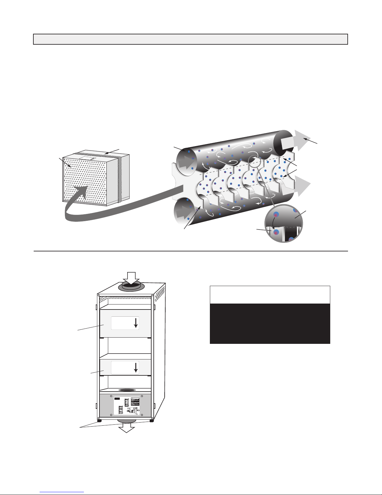
TFP (Turbulent Flow Precipitator) Technology removes health
threatening particles from the air far more effectively than most
other residential cleaners. It operates continuously at maximum
efficiency without the need for constant adjustment and cleanout.
Unlike some air cleaners, it introduces absolutely no ozone into
your home. It cleans the air throughout your home, benefiting all
the family, all the time. The TFP allows air to circulate freely,
without putting any extra load on your air distribution system.
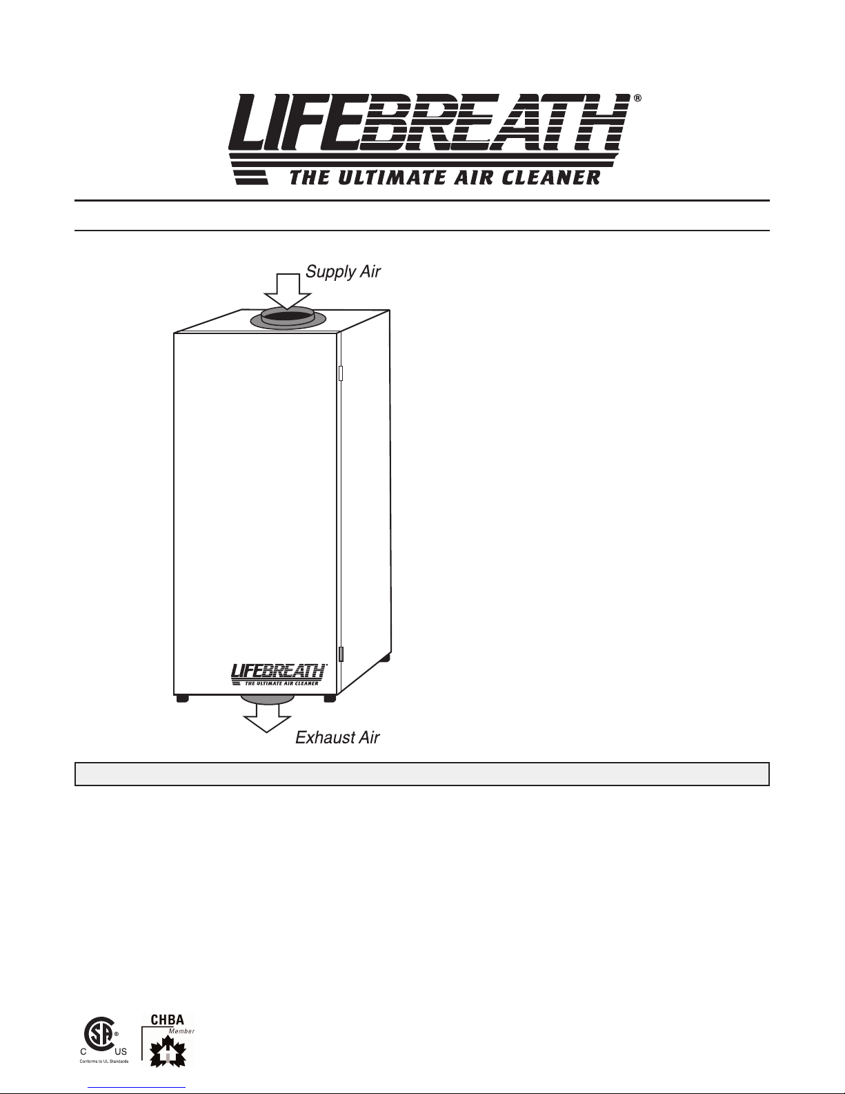
Why do I need a TFP Air Cleaner?
The air in today's homes is 3 to 5 times more polluted than outdoor
air creating health problems such as asthma, allergies, headaches,
and fatigue for the home's occupants. The Lifebreath TFP Air
Cleaner will remove 99% of these polluting particles from your
home creating a clean and comfortable environment for you and
your family.
Will I notice a difference in the amount of dust in
my home?
We have received numerous testimonials from satisfied customers
attesting to the significant drop in dust found in the homes where a
TFP is installed.
Does the TFP generate harmful ozone?
The TFP series is an induced airflow system which requires no
electric charge.
Is the TFP a patented unique technology or just
another filter?
Airia Energy Systems hold the patent for this TFP technology.
The TFP series are the only one of its kind.
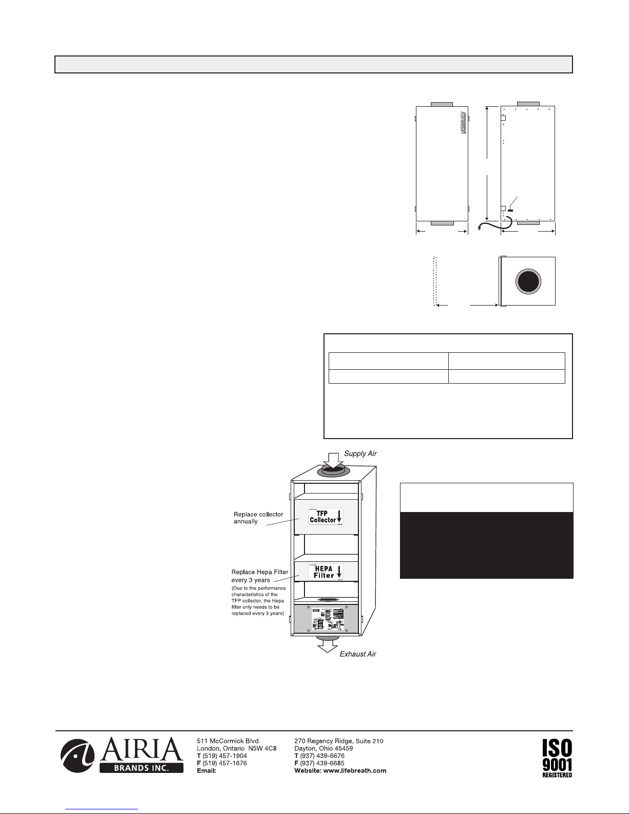
How much maintenance is involved? How often do
the filters need to be replaced?
As tested under average household dust loading, the TFP should
be inspected annually. Typically the primary collector should be
replaced annually and the secondary collector should be replaced
every 2 years.
Optional Installation Kit: Part# 99-7TFP
Includes:
– two 7” Duct Connection Collars
– 12.5’ of 7” Duct
– four Nylon Duct Zip Ties
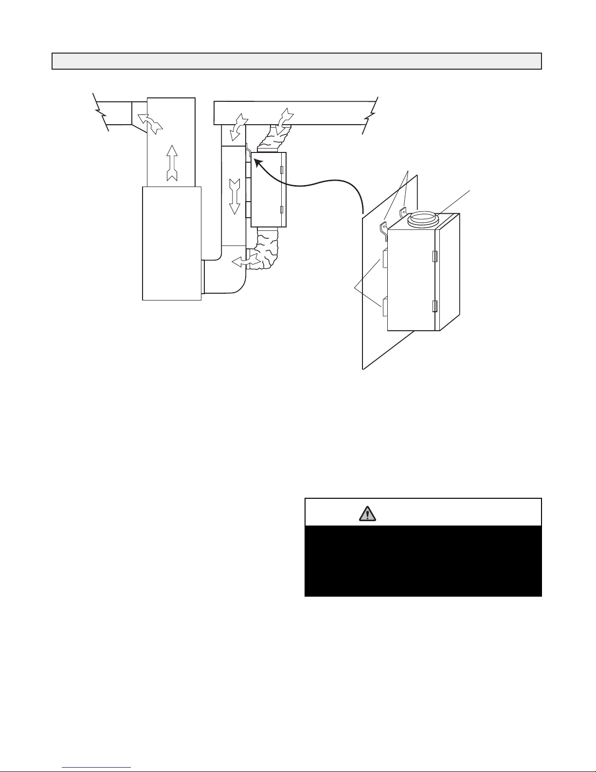
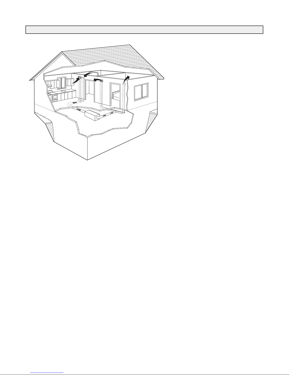
Location
The TFP should be installed in a conditioned space with easy
access for maintenance and an annual check up. A TFP is usually
installed in a basement area where air flow noise will be negligible
to the occupants.
1 TFP
4 Mounting Brackets
4 Hanging Straps
2 Collar Connections
4 Port Collar Screws
8 Mounting Bracket Screws
4 Pieces of Mounting Foam
1 Set of Installation/Operating Instructions
1 Wiring Diagram
1 Warranty Card
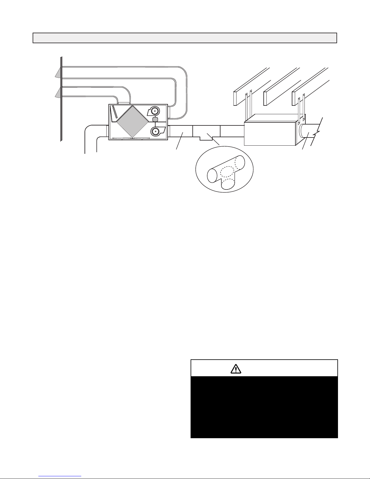
There are two basic installation options. Select the best method
for your needs.
1. TFP to a Forced Air System; use Return/Return Method
(horizontal or vertical TFP installation)
2. TFP to a Fully Dedicated HRV System
- recommended when you wish to clean the incoming air from
the HRV
3
Options
InstallationOverview
TFP uestions & Answers
Materials Supplied
Preferred Installation Options

info@lifebreath.com
4
Model TFP3000HEPA Particle Capture Rate
• Model TF 3000HE A - 99.97% efficient at .3 microns.
• A human hair is 100 microns wide.
• Spores and pollen are all larger than 8 microns.
• A micron is 1/1000 of a millimeter, or less than 1/2 of 1/10,000 of an
inch.
Note:
Minimum 16"
(406 mm) required
for service
All duct connections are 7" (178 mm)
OFF/LOW/HIGH
SWITCH
34.25"
870 mm
14.5"
368 mm 14.75"
375 mm
16"
406 mm
FRONT SIDE
END
Particle Size (microns) Percentage Caught
.3 or more 99.7%
Specifications TFP3000HEPA
Date: ___________________________________________
Tag: _____________________Qty:___________________
roject: _________________________________________
Engineer: _______________________________________
Contractor: ______________________________________
Supplier: ________________________________________
Quote#: _________________________________________
Submitted by: ____________________________________
NOTE
The TFP3000HEPA may be
installed vertically or
horizontally.
Model TFP3000HEPA
Motors and Blowers
2 speed, high efficiency PSC Motor - 150 cfm/75 cfm.
110 watts - 120 VAC - standard three prong plug to receptacle.
The TFP is equipped with a standard power supply on 5’5”
(1.6 meters) cable.
OFF/LOW/HIGH Speed Selector Switch
Select 75 cfm (Low) or 150 cfm (High).
Airflow
150cfm @ .4" WC (High Speed)
75 cfm @ .4" WC (Low Speed)
Mode TFP3000HEPA - One replaceable TFP
collector and one replaceable HEPA filter
• Easy to remove for cleaning and replacement
• Annual inspection recommended
Case
Twenty gauge prepainted galvanized steel ( 60) for superior
corrosion resistance
Weight
55 lbs. (24.4 Kgs)
Electrical Codes
Conforms to CSA and UL standards
Mounting the Wholehouse TFP - very flexible
a. Mount to the furnace return
b. Mount between the HRV and the furnace
c. Hang from a joist and duct to the furnace
d. Stand alone installation
Warranty
Units carry a five year warranty on all replacement
parts except the collectors/filters.
Options
65-503R - One replacement TFP Collector
65-502R - One replacement HEPA filter
Optional Installation Kit: Part # 99-TFP
Includes - two 7” Duct Connection Collars
- 12.5’ of 7” Non-insulated Flex Duct
- four Nylon Duct Zip Ties

Metal Hanging
Straps (Supplied)
& Mounting Bolts
7" Collar
Foam
Air
Cleaner
Return Air
Forced Air
Furnace
Return Air
Supply Air
TFP Directly Connected to Forced Air
Heating System
1. Install 7” collar (provided) on top and bottom of TFP
(Fig. 1). Use (4) 8/32” X 3/8” screws (provided).
2. Remove protective backing from pieces of foam and
stick them to the 4 corners of the TFP on the side being
mounted against the plenum.
3. Remove the 4 mounting bolts from the back of the TFP
cabinet. (Fig. 1)
4. Attach top and bottom mounting brackets (provided)
vertical to the TFP cabinet and reinstall mounting bolts.
5. Lift the TFP into position. Edge of TFP must be
positioned on plenum to allow clearance needed for
latches.
6. Install the (4) 8/32” X 3/4” mounting screws (provided)
through the brackets and into position. Tighten and
secure.
7. TFP should now sit securely against the plenum with the
foam in between.
8. Cut 2 - 7" holes in the return air plenum. Install ducting
to join TFP to the return air plenum (Fig. 2).
OTE: Do not support the weight of the TFP on the
duct. Duct must be open and not pinched.
OTE: Due to possib e noise transfer through the duct
system, it may be preferab e in some situations to hang
the TFP a short distance from the p enum, and connect
by running f exib e ducting between them. Four ny on
hanging straps are provided for this option.
TYPE 1 INSTALLATION - Option A Standard Design
The furnace fan and/or HRV must operate
continuously for Type 1 and Type 2 installations.
If they do not operate continuously, then
interlocking them electrically with the TFP is
acceptable. Consult a certified electrician.
ATTENTION
Figure 1
Figure 2

6
TYPE 1 INSTALLATION - Option B Horizontal Design
minimum 40 inches
ForcedAir
Furnace
Return Ai r
Supply Air
Air
Cleaner
The furnace fan and/or HRV must operate
continuously for Type 1 and Type 2 installations.
If they do not operate continuously, then
interlocking them electrically with the TFP is
acceptable. Consult a certified electrician.
ATTENTION
TYPE 1 INSTALLATION - Option C Vertical Design
Use Option B when Option A is not practical.
ForcedAir
Furnace
Return Ai r
Supply Air
Air
Cleaner
The furnace fan and/or HRV must operate
continuously for Type 1 and Type 2 installations.
If they do not operate continuously, then
interlocking them electrically with the TFP is
acceptable. Consult a certified electrician.
ATTENTION
Use Option C when Option A
is not practical.

TFP Connected to Heat Recovery Ventilator
Location
Locate the TFP in the main trunk of the fresh air to house line,
after the Heat Recovery Ventilator (HRV) and before any branch
lines. (Fig. 3)
Mounting
1. Locate and remove the mounting bolts (4) (used for vertical
mounting) from the sides of the TFP cabinet (Fig. 3).
2. Measure distance between the mounting bolt holes and mark
this distance on the floor/header joists at the mounting
location.
3. Use either wide head nails or screws and washers to fasten two
pairs of hanging straps to the floor joists at the mounting
location.
4. Insert the hanging bolts through prepunched holes in the
hanging straps and lift the TFP into position. Tighten and
secure bolts.
Ducting
1. Install (2) 7” collars (provided) on TFP cabinet with the (8)
8/32” X 3/8” sheet metal screws provided.
2. The ducting between the TFP and the HRV, and between the
TFP and the main supply trunk line to the house, should be
kept as straight as possible.
3. A relief opening or breathing T is required to prevent pressure
differences.
4. A short piece (1-2 foot) of flexible ducting should be used on
both sides of the TFP (Fig. 3) to reduce vibration and noise
transfer.
OTE: P ease refer to the HRV insta ation manua for proper
ducting of that app iance.
Breathing T
The “Breathing T” is designed to assist in neutralizing pressure
differences which can occur between the HRV and the TFP when
joined together. The “Breathing T” should be situated in an area
with suitable indoor air quality (IAQ). Avoid mechanical rooms
and workshops. If required, an external connection should be made
from the “Breathing T” to an area with suitable IAQ (the air
should be free of fumes, vapors, odors, or large airborne
particles etc.).
The room in which the “breathing T” is open
should be free of combustion equipment such as
gas hot water tanks and furnaces. If the “T”
must be exposed in these areas, a pressure test
(spillage or backdraft test) should be conducted
on the combustion equipment after everything is
installed.
CAUTION
TYPE 2 INSTALLATION To a Fully Dedicated HRV System
Breather Tube
(Standard
Galvanized
"Tee" Fitting)
Fresh Air
to House
Fresh Air
to House
Stale Air
from house
Air
Cleaner
HRV/ERV
Breather
Tee
Outdoors
Figure 3
7

8
TFP Independent Installation No HRV,
Radiant Heating System
Location
1. A TFP is usually installed in a basement area where air flow
noise will be negligible to the occupants.
2. A central location between the clean air supply grille and
return grille is recommended.
Mounting
Refer to “Mounting” under Type 2 Installations.
Ducting
1. Install (2) 7” collars (provided) on TFP cabinet with (8)
8/32” X 3/8” sheet metal screws provided (Fig.4).
2. Ducting will usually consist of one return with grille from one
side of the home, and one supply with grille at the opposite
end of the home (Fig. 4).
3. Ductwork should be no smaller than the size of
the port collars (7”) on the TFP.
4. Ductwork should be kept as short and straight as possible to
allow for good air circulation.
ote: For insta ations of more than one return or supp y
(greater than .5 e.s.p.), it is often necessary to add an in- ine
fan to the system as a booster.
TYPE 3 INSTALLATION Independent Duct System (No HRV)
This installation configuration is
recommended for homes without
forced air systems (i.e. radiantly
heated homes). The duct should be
sized and designed to achieve a
sweeping action from one end of the
home to the other. Considerations
may include strategic clean air
placement for allergy or asthma
sufferers.
Suggested Air Cleaner locations:
•Mechanical Room
•Attic (Extra consideration
is required to ensure heat loss
through duct work is minimized)
•Closet
Figure 4

9
TFP3000HEPA
Office or Classroom
conditioned space
TFP3000HEPA
TYPE 3 INSTALLATION Alternative Applications
Office or Classroom Application
Work Table Application

10
Operating Instructions and Annual Check-up
Operating Instructions
It is recommended the unit run continuously to provide the full
benefits of particulate removal. Use the OFF/LOW/HI H speed
selection switch to select high (150cfm) or low (75(cfm) speed.
Maintenance
Annual inspection is recommended for cleaning and replacement
of the Collectors/HEPA filter. Discard and replace the collectors
when required. Normally the primary collector is replaced
annually and the secondary collector is replaced every 3 years.
As each home differs in size, occupancy, location, infiltration rates
and homeowner needs, an estimation of when to change the
collectors is difficult.
The collectors will slide out. Some discoloration of the collector
medium can be expected. If loose dust falls from the collector, it is
time to replace it. Turn off the TFP, furnace fan and HRV. Open
the door and slide out the collectors to check buildup and do an
annual inspection of the overall unit. Before replacing any
collectors, vacuum any dust inside the cabinet or from the
surrounding area.
When replacing the collectors, make sure the directional arrows
are noted and the collectors are installed correctly. Close the door
and restart the TFP, furnace and HRV fan.
If your TFP is installed with a forced air heating system, you are
still required to use the recommended furnace filter. This may be a
good time to inspect this filter as well.
When new collectors are required, call your dealer.
Model TF 3000HE A - 1 TF Collector, 1 HE A filter
Disconnect all power sources before attempting
any service.
CAUTION

Wiring Diagram
BLUE
BLACK
BLACK
BLACK
G
Neutral WHITE
Line BLACK
Ground GREEN
HIGH SPEED
OFF
LOW SPEED
DEFOND
SWITCH
120 VAC
60 Hz
FAN MOTOR
1
2
3
TRANSFORMER
TERMINAL BLOCK
BLACK
WHITE
BLUE
WHITE
BLUE
BLACK
BLACK
BLUE
RED
WHITE
RED
G
GREEN/YELLOW
370V~50/60HZ
CAPACITOR
10UF
DOOR
SWITCH
RED
RED
BROWN
CAUTION /ATTENTION
11

12
info@lifebreath.com
LEAVE FOR HOMEOWNER
TO BE COM LETED BY CONTRACTOR AFTER INSTALLATION
Installing Contractor _________________________________________Telephone / Contact _____________________
Serial Number______________________________________________Installation Date ________________________
Model _________________________________________________________________________________________
Register for your warranty at www.lifebreath.com
Airia will require the Model and Serial Number to register the unit.

12
LAISSEZ CE MANUEL CHEZ LE PR PRIÉTAIRE
SECTI N QUE L'ENTREPRENEUR D IT REMPLIR APRÈS L'INSTALLATI N
Entrepreneur installateur _____________________________________Téléphone / Contact _____________________
Numéro de série ____________________________________________Date d'installation _______________________
Modèle ________________________________________________________________________________________
Pour enregistrer votre garantie, visitez le site ww.lifebreath.com
Vous devez avoir les numéros de modèle et de série pour valider la garantie.

Schéma de câblage
BLEU
NOIR
NOIR
NOIR
T
Neutre BLANC
Ligne NOIR
Terre VERT
HAUTE VITESSE
ARRÊT
BASSE VITESSE
COMMUTATEUR
DEFOND
120 VCA
60 hertz
MOTEUR DU
VENTILATEUR
1
2
3
TRANSFORMATEUR
BLOC À BORNES
NOIR
BLANC
BLEU
BLANC
BLEU
NOIR
NOIR
BLEU
ROUGE
BLANC
ROUGE
T
VERT/JAUNE
CONDENSATEUR
370 V - 50/60Hz
10µF
COMMUTATEUR
DE PORTE
ROUGE
ROUGE
BRUN
CAUTION /ATTENTION
11

10
Instructions d'utilisation et vérification annuelle
Instructions d'utilisation
Pour profiter d'une élimination maximale des particules qui
flottent dans l'air, on vous conseille de laisser marcher l'appareil
continuellement. Servez-vous du sélecteur de vitesse
ARRÊT/BASSE/HAUTE pour choisir la vitesse élevée
(150 pi cu/min) ou la vitesse réduite (75 pi cu/min).
Entretien
On recommande de faire une inspection annuelle pour procéder au
nettoyage et au remplacement des collecteurs et/ou du filtre
HEPA. Jetez et remplacez les collecteurs quand c'est nécessaire.
Habituellement, le collecteur primaire est remplacé chaque année,
tandis qu'on remplace le collecteur secondaire à tous les trois ans.
Comme chaque maison est différente en ce qui concerne les
dimensions, le nombre de personnes, l'emplacement, les taux
d'infiltration et les besoins du propriétaire, il est difficile d'estimer
quand les collecteurs devront être changés.
On glisse les collecteurs pour les sortir. Il faut s'attendre à une
certaine décoloration du médium filtrant et, quand on remarque
qu'il tombe de la poussière d'un collecteur, cela veut dire qu'il est
temps de le remplacer. Arrêtez l'épurateur à PFT, le ventilateur
rotatif de la fournaise et le ventilateur à récupération de chaleur
(VRC). Ouvrez la porte et sortez les collecteurs pour voir s'il y a
une accumulation de saleté. Procédez en même temps à une
inspection annuelle de tout l'appareil. Avant de remettre des
collecteurs en place, servez-vous d'un aspirateur électrique pour
enlever la poussière à l'intérieur du caisson et aux alentours. Au
moment d'introduire les collecteurs, tenez compte de la position
des flèches directionnelles et installez-les correctement. Fermez la
porte et remettez l'épurateur à PFT, la fournaise et le VRC en
marche.
Si votre épurateur à PFT a été installé avec un système de
chauffage à air pulsé, vous devez continuer d'utiliser le filtre
recommandé pour la fournaise. Vous devriez profiter de cette
vérification annuelle pour inspecter le filtre de la fournaise.
Quand vous avez besoin de nouveaux collecteurs, appelez votre
concessionnaire.
odèle TFP3000HEPA - Un collecteur PFT, un filtre HEPA
Avant de commencer n'importe quelle tâche
d'entretien, il faut débrancher toutes les sources de
courant.

9
TFP3000HEPA
Bureau ou salle de classe
Espace climatisé
TFP3000HEPA
INSTALLATION DE TYPE 3 Autres utilisations possibles
Dans un bureau ou une salle de classe
Sous une table de travail

8
Installation indépendante de l'épurateur à PFT -
pas de V C - système de chauffage par
rayonnement
Emplacement
1. L'épurateur à PFT est habituellement installé dans le sous-sol
où le faible bruit qu'il produit ne dérangera pas les personnes
qui habitent la maison.
2. Nous recommandons un endroit central entre la grille
d'alimentation en air propre et la grille de retour ou reprise.
Montage
Consultez la section “ ontage” des instructions d'installation de
type 2.
Conduits
1. Posez les deux (2) colliers de 7 po (fournis) sur le caisson de
l'épurateur à PFT avec les huit (8) vis à tôle de 8/32 po x 3/8 po
qui sont fournies (Fig. 4).
2. Les canalisations comprendront habituellement un conduit de
reprise ou retour avec une grille sur un côté de la maison et un
conduit de distribution avec une grille à l'extrémité opposée de
la maison (Fig. 4).
3. Ces canalisations ne doivent jamais être plus petites que le
diamètre des colliers d'orifice (7 po) sur l'épurateur à PFT.
4. Afin d'assurer une bonne circulation de l'air, les conduits
doivent être aussi courts et droits que possible.
Remarque : Pour les installations comprenant plus d'un
conduit de reprise ou de distribution (avec une pression
statique extérieure dépassant 0,5), il aut souvent ajouter un
ventilateur en ligne pour ren orcer le système.
INSTALLATION DE TYPE 3 Système à conduit indépendant (pas de V C)
On recommande cette configuration
d'installation pour les maisons sans système à
air pulsé (c'est-à-dire pour les résidences
dotées d'un système de chauffage par
rayonnement). La canalisation devrait être
dimensionnée et conçue de manière à obtenir
une action généralisée d'un bout à l'autre de
la maison. Il faut tenir compte des besoins
particuliers en air propre des personnes qui,
par exemple, souffrent d'allergies ou
d'asthme.
Emplacements suggérés pour l'épurateur d'air
:
• Salle des appareils mécaniques
• Grenier (mais en s'efforçant de minimiser
la perte de chaleur dans la canalisation)
• Placard
Figure 4

7
Épurateur à PFT raccordé à un ventilateur à
récupération de chaleur
Emplacement
L'épurateur à PFT devrait être placé dans la canalisation principale
de l'adduction d'air neuf vers la maison, après le ventilateur à
récupération de chaleur (VRC) et avant toute canalisation
secondaire (Fig. 3).
Montage
1. Pour une suspension verticale (Fig. 3), trouvez les boulons de
montage (4) sur le côté du caisson de l'épurateur à PFT et
ôtez-les.
2. esurez la distance entre les boulons et marquez-la sur la
solive de plancher ou le linçoir qui servira à suspendre
l'épurateur à PFT.
3. Attachez les courroies de suspension aux solives de plancher,
en utilisant des clous ou des vis à tête évasée avec des
rondelles.
4. Introduisez les boulons de suspension à travers les trous déjà
percés dans les courroies et soulevez l'épurateur à PFT en place.
Serrez bien les boulons.
Conduits
1. Avec les huit (8) vis à tôle de 8/32 po x 3/8 po qui sont
fournies, installez les deux (2) colliers de 7 po (fournis) sur le
caisson de l'épurateur à PFT.
2. Il faut garder aussi droite que possible la canalisation entre
l'épurateur à PFT et le ventilateur à récupération de chaleur
(VRC), ainsi qu'entre l'épurateur à PFT et l'adduction d'air
principale à la maison.
3. Un orifice de sûreté ou un T d'aération est nécessaire pour
prévenir les différences de pression.
4. Sur les deux côtés de l'épurateur à PFT (Fig. 3), vous devrez
utiliser une courte pièce (1 à 2 pieds) de gaine flexible. Vous
réduirez ainsi la transmission de la vibration ou du bruit, le cas
échéant.
REMARQUE : Pour bien canaliser cet appareil, n'oubliez pas
de consulter le manuel d'installation du ventilateur à
récupération de chaleur (VRC).
T d'aération
Le “T d'aération” a pour fonction d'aider à neutraliser les
différences de pression qui peuvent se produire entre le VRC et
l'épurateur à PFT, lorsque ces deux appareils sont raccordés
ensemble. Il faut placer ce “T d'aération” dans un endroit où la
qualité de l'air intérieur (QAI) est assez bonne. Évitez les ateliers
de travail et les salles d'appareils mécaniques. Au besoin, effectuez
un raccordement externe entre le “T d'aération” et un endroit où la
qualité de l'air intérieur (QAI) est convenable. (L'air devrait être
exempt d'émanations, de vapeurs, d'odeurs, de grosses particules
en suspension, etc.).
INSTALLATION DE TYPE 2 À un système V C entièrement spécifique
La salle ou pièce dans laquelle le “T d'aération” est
ouvert devrait être exempte d'appareils à
combustion comme des chauffe-eau et/ou des
fournaises à gaz. Si le “T” doit être exposé dans un
tel endroit, il faut soumettre l'équipement à
combustion à un essai de pression (un test de
débordement ou de contre-courant) après avoir
achevé l'installation de tout l'équipement prévu.
Tube reniflard
(raccord en T
galvanisé
standard)
Air neuf
vers la maison
Air neuf
vers la maison
Air vicié
provenant
de la maison
Épurateur
d'air
VRC/VRE
T d'aération
Extérieur
Figure 3

6
INSTALLATION DE TYPE 1 - Option B Conception horizontale
INSTALLATION DE TYPE 1 - Option C Conception verticale
Choisissez l'option B lorsque l'option A n'est pas pratique.
Fournaise
à air pulsé
Air repris
Air alimenté
Épurateur
d'air
Choisissez l'option C lorsque l'option A
n'est pas pratique.
minimum 40 pouces
Fournaise
à air pulsé
Air repris
Air alimenté
Épurateur
d'air
le ventilateur rotatif de la fournaise doit fonctionner
sans interruption pour des installations de type 1.
le ventilateur rotatif de la fournaise doit fonctionner
sans interruption pour des installations de type 1.

5
Bandes de suspension
en métal (fournies)
et boulons de montage
Collier de 7 po
Mousse
Épurateur
d'air
Return Air
Fournaise
à air pulsé
Air repris
Air alimenté
Épurateur à PFT raccordé directement au système
de chauffage à air pulsé
1. Posez les colliers de 7 po (fournis) au sommet et au bas
de l'épurateur à PFT (Fig. 1). Servez-vous de quatre (4)
vis de 8/32 po x 3/8 po (fournies) pour chaque collier.
2. Enlevez l'endos protecteur des morceaux de mousse et
collez-les aux quatre coins de l'épurateur à PFT sur le
côté qui sera monté contre le plénum.
3. Retirez les quatre boulons de montage de l'arrière du
caisson de l'épurateur à PFT (Fig. 1).
4. Attachez les supports de montage (fournis) du haut et du
bas verticalement par rapport au caisson de l'épurateur à
PFT et remettez les boulons de montage en place.
5. Soulevez l'épurateur à PFT pour le mettre place. Le bord
de l'épurateur à PFT doit être placé sur le plénum, de
manière à laisser des espaces libres suffisants pour les
loquets.
6. Posez les quatre (4) vis de montage de 8/32 x 3/4 po
(fournies) dans les supports et en position. Serrez-les
pour bien assujettir l'assemblage.
7. L'épurateur à PFT devrait maintenant être bien ajusté
contre le plénum, avec une couche de mousse entre les
deux surfaces.
8. Découpez deux trous de 7 pouces de diamètre dans le
plénum de reprise d'air (Fig. 2)
REMARQUE : e supportez pas le poids de l'épurateur à
PFT à partir du conduit. Le conduit doit être ouvert et jamais
pincé.
REMARQUE : À cause de la transmission possible du bruit
dans le réseau de canalisations, il pourrait être pré érable,
dans certains cas, de suspendre l'épurateur à PFT à une courte
distance du plénum et de les raccorder au moyen d'une gaine
lexible. On vous ournit quatre courroies de suspension en
nylon pour cette option.
INSTALLATION DE TYPE 1 - Option A Conception standard
Figure 1
Figure 2
le ventilateur rotatif de la fournaise doit fonctionner
sans interruption pour des installations de type 1.
Other manuals for Lifebreath TFP3000HEPA
1
Table of contents
Other Lifebreath Air Cleaner manuals
Popular Air Cleaner manuals by other brands

Aerus
Aerus Pure & Clean Plus A1041A manual

Pure n Natural Systems
Pure n Natural Systems LA-1000-FM Installation manual and user's guide

Field Controls
Field Controls 46377000 manual

Flanders
Flanders FFI Alpha 2000 Specification sheet

Daikin
Daikin MC70LBFVM Operation manual

Rabbit Air
Rabbit Air MinusA2 SPA-700A quick start guide