Description
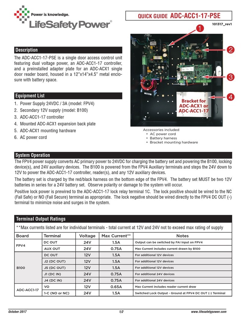
The ADC-AC-X1100-4PSE is a four door access control unit
featuring dual voltage power and contains one prewired
ADC-X1100 and one prewired ADC-X100 expansion board.
The 20”x 16”x 4.5” metal enclosure includes battery space.
Equipment List
1. Pre installed AC power cord
2. Power Supply 24VDC / 3A (model: FPV4)
3. Pre-installed ADC-X1100 controller
4. Secondary 12V supply (model: B100)
5. Distribution module (model: F8P)
6. Pre-installed ADC-X100 expansion module
QUICK GUIDE ADC-AC-X1100-4PSE
1/2 www.lifesafetypower.com
Terminal Output Ratings
**Max currents listed are for individual terminals - total current at 12V and 24V not to exceed max rating of supply
Board Terminal Voltage Max Current** Notes
FPV4 DC OUT 24V 3A Set for continuous output. FAI controlled by F8P
AUX OUT 24V 1.5A For additional 24V devices
B100 DC OUT 12V 2A For additional 12V devices
F8P Outputs 7 & 8 12 or 24V 2.5A For additional 12V or 24V devices with or without FAI control
ADC-X1100 OUT1 (NO or NC) 24V 1.5A Switched Lock Output - Ground at F8P OUT3 (-) Terminal
OUT3 (NO or NC) 24V 1.5A Switched Lock Output - Ground at F8P OUT4 (-) Terminal
ADC-X100 OUT1 (NO or NC) 24V 1.5A Switched Lock Output - Ground at F8P OUT5 (-) Terminal
OUT3 (NO or NC) 24V 1.5A Switched Lock Output - Ground at F8P OUT6 (-) Terminal
System Operation
The FPV4 power supply converts AC primary power to 24VDC for charging the battery set and powering the ADC-X1100
controller, ADC-X100 expansion module, B100, locking device(s), and 24V auxiliary devices. The B100 is powered from
the FPV4 main output terminals and steps the 24V down to 12V to power reader(s) and other 12V auxiliary devices. The
F8P distribution module provides 8 separate Class 2 outputs, each of which can be set for 12V or 24V and for fire alarm
control.
The battery set is charged by the red/black harness in the top right corner of the FPV4. The battery set MUST be two 12V
batteries in series for a 24V battery set. Observe polarity or damage to the system will occur.
Positive lock power is prewired to the ADC-X1100 and ADC-X100 lock relay Common terminals. The lock positive should
be wired to the NC (Fail Safe) or NO (Fail Secure) terminal as appropriate. Each lock negative should be wired directly to
the F8P (-) terminal to minimize noise and surges in the system.
September 2020
Accessories included
• AC power cord
• Battery harness
090920_rev1


