manuals.online logo
Brands
  1. Home
  2. •
  3. Brands
  4. •
  5. LifeSafety Power
  6. •
  7. Control Unit
  8. •
  9. LifeSafety Power ADC-ACC1-17-PSE User manual

LifeSafety Power ADC-ACC1-17-PSE User manual

Description
The ADC-ACC1-17-PSE is a single door access control unit
featuring dual voltage power, an ADC-ACC1-17 controller,
and a preinstalled adapter plate for an ADC-ACX1 single
door reader board, housed in a 12”x14”x4.5” metal enclo-
sure with battery space.
Equipment List
1. Power Supply 24VDC / 3A (model: FPV4)
2. Secondary 12V supply (model: B100)
3. ADC-ACC1-17 controller
4. Mounted ADC-ACX1 expansion back plate
5. ADC-ACX1 mounting hardware
6. AC power cord
QUICK GUIDE ADC-ACC1-17-PSE
Bracket for
ADC-ACX1 or
ADC-ACC1-17
Accessories included
• AC power cord
• Battery harness
• Bracket mounting hardware




October 2017 1/2 www.lifesafetypower.com
Terminal Output Ratings
**Max currents listed are for individual terminals - total current at 12V and 24V not to exceed max rating of supply
Board Terminal Voltage Max Current** Notes
FPV4 DC OUT 24V 1.5A Output can be switched by FAI Input on FPV4
AUX OUT 24V 0.75A Max Current includes current drawn by B100
B100
DC OUT 12V 1.5A For additional 12V devices
J2 (DC OUT) 12V 1.5A For additional 12V devices
J5 (DC OUT) 12V 1.5A For additional 12V devices
J1 (DC IN) 24V 0.75A For additional 24V devices
J4 (DC IN) 24V 0.75A For additional 24V devices
ADC-ACC1-17 VO 12V 0.65A Max Current includes reader current draw
1-C (NO or NC) 24V 1.5A Switched Lock Output - Ground at FPV4 DC OUT (-) Terminal
System Operation
The FPV4 power supply converts AC primary power to 24VDC for charging the battery set and powering the B100, locking
device(s), and 24V auxiliary devices. The B100 is powered from the FPV4 Auxiliary terminals and steps the 24V down to
12V to power the ADC-ACC1-17 controller, reader(s), and any 12V auxiliary devices.
The battery set is charged by the red/black harness on the bottom edge of the FPV4. The battery set MUST be two 12V
batteries in series for a 24V battery set. Observe polarity or damage to the system will occur.
Positive lock power is prewired to the ADC-ACC1-17 lock relay terminal 1C. The lock positive should be wired to the NC
(Fail Safe) or NO (Fail Secure) terminal as appropriate. The lock negative should be wired directly to the FPV4 DC OUT (-)
terminal to minimize noise and surges in the system.
101317_rev1
LifeSafety Power Inc.
750 Tower Road, Unit B
Mundelein, IL 60060 USA
www.lifesafetypower.com
Tel (888) 577-2898
info@lifesafetypower.com
Important: All information, including illustrations, is believed to be reliable. Users, however, should independently evaluate
the suitability of each product for their particular application. LifeSafety Power makes no warranties as to the accuracy or
completeness of the information, and disclaims any liability regarding its use. LifeSafety Power’s only obligations are those
in the LifeSafety Power Standard Terms and Conditions of Sale for this product, and in no case will LifeSafety Power or its
distributors be liable for any incidental, indirect, or consequential damages arising from the sale, resale, use, or misuse of
the product. Specifications are subject to change without notice. In addition, LifeSafety Power reserves the right to make
changes—without notification to Buyer—to processing or materials that do not affect compliance with any applicable specification.
ADC-ACC1-17-PSE QUICK GUIDE 2
October 2017 2/2 www.lifesafetypower.com
DC OUT
BR BR
DC IN
DC OUT
DC IN
FAULT
DC IN
DC OUT
+
–
i
Power Supply voltage
factory pre-set for 24V
DO NOT CHANGE!
L L V- I- I+ V+ NC NC
NO NOC C _+
BATTERY
24VDC
24VDC
TB1
TB2
TB3
TB5 TB4
TB1
TB5
ADC-ACC1-17
B100
FPV4
IN1
IN2
VO
LED
LED BZR
BZR CLK
CLK DAT
DAT GND
VO
GND
VIN
GND
NO
1-CNC
NO
2-C
NC
CAT5
24V
+
+
-
24VDC
12VDC
12VDC
24VDC
24 to 12V converter
24V PS/Charger
L N
AC ON
FAI
AUXILIARY MAIN
DC
AUX
SYS FLT AC FLT
FAI INPUT
J7
Connect Lock to either
NO or NC based on type
of lock and system requirements
ORN/BLK
BLUE
VIO/BLK
RED/BLK
Cabinet
Tamper
Switch
Reference ADC-ACC1-17 Manual
for Reader and Input Information
Locking
Device
+
-
Attach AC Line cord to
FPV4 AC Input Terminals
B100 Screw Terminals
May be used for
12V Aux Power
12V
Battery
- +
12V
Battery
- + Vo Terminal may be
used for 12V Aux Power
(650mA Max w/ Reader)
DC OUT Terminals
may be used for
24V Aux Power
CURRENT DRAW
From Terminal Typical Maximum
FPV4 - 24V MAIN OUT 0.5A 1.5A
FPV4 - 24V AUX OUT 0.25A 0.75A
B100 - 12VDC OUT 0.5A 1.5A
Power Budget
Wiring Diagram

Other LifeSafety Power Control Unit manuals

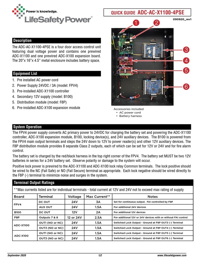
LifeSafety Power ADC-AC-X1100-4PSE User manual

LifeSafety Power

LifeSafety Power ADC-AC-X1100-4PSE User manual

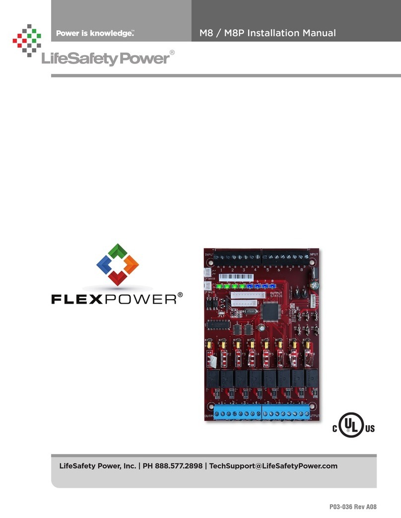
LifeSafety Power M8 User manual

LifeSafety Power

LifeSafety Power M8 User manual

LifeSafety Power FlexPower C4 User manual

LifeSafety Power

LifeSafety Power FlexPower C4 User manual

LifeSafety Power FlexPower Netlink NL2 Owner's manual

LifeSafety Power

LifeSafety Power FlexPower Netlink NL2 Owner's manual

LifeSafety Power FlexPower Netlink NL2 Owner's manual

LifeSafety Power

LifeSafety Power FlexPower Netlink NL2 Owner's manual

Popular Control Unit manuals by other brands

Nakanishi E3200 Series Operation manual

Nakanishi

Nakanishi E3200 Series Operation manual

Quectel LTE-A Series Hardware design

Quectel

Quectel LTE-A Series Hardware design

Rittal SV9343.070 Assembly and operating instructions

Rittal

Rittal SV9343.070 Assembly and operating instructions

Bosch Rexroth IndraControl VCP 25.2 Project planning manual

Bosch

Bosch Rexroth IndraControl VCP 25.2 Project planning manual

Geca CTP24 user manual

Geca

Geca CTP24 user manual

Texas Instruments TSC4270 user guide

Texas Instruments

Texas Instruments TSC4270 user guide

LeakSmart PRO Installation and operation manual

LeakSmart

LeakSmart PRO Installation and operation manual

Ensemble Designs Avenue 5030 user guide

Ensemble Designs

Ensemble Designs Avenue 5030 user guide

Motorola MVME2300SC Series Installation and use

Motorola

Motorola MVME2300SC Series Installation and use

Aliaxis VEE Series manual

Aliaxis

Aliaxis VEE Series manual

ABB ACSM1 Series Hardware manual

ABB

ABB ACSM1 Series Hardware manual

HYDAC International FMMHP Operating and maintenance instructions

HYDAC International

HYDAC International FMMHP Operating and maintenance instructions

Gan Systems GS-EVB-HB-66508B-RN Technical manual

Gan Systems

Gan Systems GS-EVB-HB-66508B-RN Technical manual

NextLight Pro Series user manual

NextLight

NextLight Pro Series user manual

Sporlan B5D Installation and servicing instructions

Sporlan

Sporlan B5D Installation and servicing instructions

Axis 2191 installation guide

Axis

Axis 2191 installation guide

Fortis 8469100 manual

Fortis

Fortis 8469100 manual

AMX DG DVI MTP quick start guide

AMX

AMX DG DVI MTP quick start guide

manuals.online logo
manuals.online logoBrands
  • About & Mission
  • Contact us
  • Privacy Policy
  • Terms and Conditions

Copyright 2025 Manuals.Online. All Rights Reserved.