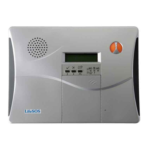
LifeSOS LS-30 User manual

L
Li
if
fe
eS
SO
OS
S
THE HOME SECURITY & AUTOMATION SYSTEM
FOR YOUR FUTURE NEEDS
Model LS-30
OPERATION MANUAL

NOTE: The changes or modifications not expressly approved by the party responsible
for compliance could void the user’s authority to operate the equipment.
The comply with the FCC RF exposure compliance requirements, this device and its
antenna must not be co-located or operating to conjunction with any other antenna or
transmitter.
This device complies with Part 15 of the FCC Rules. Operation is subject to the
following two conditions: (1) this device may not cause harmful interference, and (2) this
device must accept any interference received, including interference that may cause
undesired operation.

TableofContents Page
INTRODUCTION & INSTALLATION --------------------------------------------------------- 1
BASE UNIT -------------------------------------------------------------------------------------- 3
STATUS INDICATORS ------------------------------------------------------------------------ 4
ELECTRICAL INSTALLATION ------------------------------------------------------------- 5
MECHANICAL INSTALLATION --------------------------------------------------------- 6
USER OPERATION -------------------------------------------------------------------------------- 7
INITIAL STATE ------------------------------------------------------------------------------- 9
(2) System Check ------------------------------------------------------------------------------ 10
(2-1) Telephone Number Check ---------------------------------------------------------- 11
(2-2) Voice Check -------------------------------------------------------------------------- 12
(2-3) Device Check ------------------------------------------------------------------------ 12
(3) Master Mode -------------------------------------------------------------------------------- 13
OPERATION MODES OF LS-30 ----------------------------------------------------------- 15
REACTION OF LS-30 TO DIFFERENTALARMS ------------------------------------- 16
ANSWERING THE CALL FROM LS-30 ------------------------------------------------- 17
DIAL-IN CONTROL ------------------------------------------------------------------------- 18
INSTALLER & CMS SETTINGS -----------------------------------------------------------------19
(4) Installer Mode ------------------------------------------------------------------------------ 20
(4-1) Set Timer --------------------------------------------------------------------------- 20
(4-2) Set Telephone ---------------------------------------------------------------------- 22
(4-2-1) Set Telephone Number -------------------------------------------------- 24
(4-3) Set Sound --------------------------------------------------------------------------- 26
(4-4) Set Device -------------------------------------------------------------------------- 28
(4-4-1) Change Device Setting ------------------------------------------------- 29
(4-5) Set Siren ---------------------------------------------------------------------------- 31
(4-6) Set Misc. --------------------------------------------------------------------------- 32
(4-7) Set GSM ---------------------------------------------------------------------------- 33
(5) CMS Mode --------------------------------------------------------------------------------- 34
SPECIFICATIONS--------------------------------------------------------------------------------- 35
APPENDIX ------------------------------------------------------------------------------------------- 36
A-1, Remote Message Display.
A-2, Connection Diagram for RS-232 Computer Interface
A-3, Connection Diagram for Ethernet Adaptor and Internet Remote Access
A-4, Connection Diagram for X-10 Power Line Interface
A-5, Terminal Board Connection
A-6, Connection Diagram for GSM Module
A-7, Using the Same Telephone Line to Connect LS-30, Fax Machine and Telephone
Answering Machine
A-8, Partial Arm for Group Numbers “91” to “99”
ACCESSORIES -------------------------------------------------------------------------------------- 39
Remote Controller ------------------------------------------------------------------------------ 40
Magnetic Contact Transmitter ---------------------------------------------------------------- 41
PIR Motion Detector --------------------------------------------------------------------------- 44
Glass Break Detector -------------------------------------------------------------------------- 48
Smoke Detector --------------------------------------------------------------------------------- 50
Outdoor Wireless Siren With Light ----------------------------------------------------------- 52

INTRODUCTION & INSTALLATION
1

Thank you for purchasing the LS-30 IP Based Wireless Home Security & Control System.
By adopting modern microprocessor control and communication technologies, the LS-30 is designed
to provide all the most advanced features that you need to protect your home and business. Moreover,
you can operate the system and read its status by using the proprietary GUI (Graphic User Interface)
HyperSecureLink through the Internet, from all over the world*. The LS-30 is not only a security
system but also a home automation controller that allows you to set as many as 16 programmable
switches to execute daily commands throughout a whole week. With optional temperature, humidity
and other sensors, the LS-30 also operates as an environmental monitoring center to report and prevent
floods, gas leaks and other hazards.
Although the LS-30 is a very powerful device, thanks to the interactive HMI (Human Machine
Interface) programming technology, its operation is simple. Just follow the instructions shown on the
LCD display by answering the questions with YES/NO buttons or pressing the correct keys, and the
settings are done. You can also set up the system on your laptop or PC using the optional RS-232
adapter and HyperSecureLink software.
The set up is simple, switch on back up battery, connect the Base Unit to power, enroll sensors and
accessories, connect the telephone line, set the telephone numbers and record the voice messages, and
then the LS-30 is at your service.
As your security requirements grow and you become more familiar with the system, you can expand
and accessorize the LS-30 to meet your specific needs. Simply call your local dealer; trained
professionals can answer any questions you have regarding additional accessories.
Main Features:
Security and home automation.
Computer and Internet interface to download and upload system parameters and events.
Interactive programming with 16 x 2 LCD display.
Detailed 512-event log with time tag.
288 sensors /zones can be accommodated.
16 programmable X-10 switches.
Receiving RF signal strength indication and jamming detection.
Robust multi-million RF coding and special transmission timing design, avoiding interferences.
Responds to panic, burglary, fire, medical alarm and environmental hazards.
Burglar zones with supervised sensors, door and window open /close detection.
Special Monitoring mode to record all the activities in the protected area without triggering the alarm.
9 partial arm zones, working independently of the main zones, make LS-30I operate as 10 independent
systems.
Temperature, humidity and other sensors for environment monitoring.
Built-in voice dialer stores up to 10 phone numbers, 1 pager and 2 CMS data links.
Hands-free speaker-phone, two-way voice communication.
Dial-in control of listen-in, arm, disarm, event report and switch control.
Latchkey function to inform parents when kids leave or return home.
AC power loss and restore will inform the user immediately.
Inactivity monitoring to take care of the elderly or physically challenged.
Optional GSM communication module.
*For Internet connection, an optional EthernetAdapter is needed.
2

BASE UNIT
FrontPanel SidePanel
Rear Panel
1. ALARM OUT SELECTOR: Set the Alarm Relay Output terminals as +12VDC output or dry contacts
when the relay activates.
2. Terminal Board (Refer to the APPENDIX A-5): One pair of Alarm Relay contacts, +12VDC (12~15V
/200mA max.) output and Ground terminal, three wire sensor inputs, twoAux. Outputs.
3. COM1 (Refer to the APPENDIX A-2, A-3, A-6): Communication port for RS-232 Adaptor, Ethernet
Adaptor or GSM module. (RS-232 adaptor, GSM module and Ethernet adaptor are optional).
4. COM2 (Refer to the APPENDIX A-4): Communication port for X-10 Power Line Interface controller
and RS-485 interface (reserved).
5. AUX Audio (Refer to the APPENDIX A-6): Audio I/O for GSM module (GSM module is optional).
Key Board & Status Display
Emergency Buttons
Speaker
LCD Display
Key Board
LED status
Microphone
To trigger the Emergency help,
press both buttons simultaneously.
Speaker Volume Control
Power adaptor I/P
2. Terminal Board
Tele
p
hone Line I/P
Phone Set Connecto
r
Wire Duc
t
1.ALARM OUT SELECTO
R
3.COM1
4.COM2
5.AUX. Audio
3
Key A& AWAYARM
Key B& HOME ARM
Key C,STATUS CLEAR & PAUSE
Key D, DISARM & ENTER
Key 1 & Hands-free Telephone
Key 2 & X-10 Switch Control
Key 3 & Alarm Relay Control
Key 4& Door Open (Reserved)
YES NO FUNC / ESC

STATUS INDICATORS
There are three LED indicators in green, yellow and red colors on the front panel. They represent the
system operation mode and alarm/ warning status as listed in the following table.
Note: If there are any alarm or warning messages in the event log memory, the ALARM (red LED)
and WARN (yellow LED) indicators will be lighted. These indicators will be turned off after the
user runs the Event Check function (Refer to (2) System Check-Event Check) or press (Hotkey)
in Disarm Mode.
Sensors & Zones
All sensors are divided into five main categories
1. 32 Controller /Panic Devices (C): Remote Controller, Keypad.
2. 128 Burglary Sensors (B): Door Magnet, PIR (Passive Infrared), Glass Break Detector,
Pressure Change Detector.
3. 64 Fire Sensors (F): Smoke Detector, Gas Detector.
4. 32 Medical Help Transmitters (M): Medical Button, Inactivity Detector.
5. 32 Special Sensors (S): Flood Detector, Temperature Sensor, Humidity Sensor.
All the sensors are numbered with two double-digit zone numbers from (01-01) to
(99-99), the first two-digit number is the Group number and the second
two-digit number is the Unit number, set by the Installer in the initial
installation.
Ex.1, C 01-02: Controller number 01-02 (Group number 01, Unit number 02).
Ex.2, B 02-04: Burglar Sensor number 02-04 (Group number 02, Unit number 04).
Group number: The user can group several sensors by using the same Group Number.
For example, the sensors in the first floor can be assigned as group number “01”
and the sensors in the second floor can be assigned as group number “02”, or you
can just use group “01” for all sensors.
Note: The group number ”00” is reserved for the Base Unit and group numbers “91” to
“99” are reserved for the Partial Arm Zones (Please refer toAPPENDIX A-8).
State LED Red Yellow Green
DISARM OFF OFF Flash
HOME OFF Flash OFF
AWAY Flash OFF OFF
DISARM with Warning Message OFF ON Flash
DISARM with Alarm Message ON OFF Flash
DISARM with Warning & Alarm
Message
ON ON Flash
HOME with Warning Message OFF ON OFF
HOME with Alarm Message ON Flash OFF
HOME or AWAY with Warning
& Alarm Message
ON ON OFF
AWAY with Warning Message Flash ON OFF
AWAY with Alarm Message ON OFF OFF
4
ALARM WARM
AWAY HOME DISARM

ELECTRICAL INSTALLATION
1. Switch on the internal rechargeable battery.
The LS-30 Base Unit can accommodate 2 rechargeable battery packs.
Battery pack 1 is 9.6V/900mA(built-in) and Battery pack 2 (optional) is 9.6V/600mA, providing 6-15
hours back up time.
2. Plug in the power adaptor.
3. Key in Installer the password. (The default Installer password is “1234”.)
(Refer to the Passwords Block.)
4. Enter the Installer Mode. (Refer to (4) Installer Mode).
5. Program the basic settings
a) Telephone numbers
(Refer to (4-2) Set Telephone – (4-2-1) Set Telephone Number)
b) Record voice message
(Refer to (4-3) Set Sound-Record Voice)
c) Enroll all the wireless devices by recording their ID codes in the Base Unit.
(Referto(4-4) Set Device-Enroll Device)
6. Set other functions if necessary.
7. Connect the telephone line, GSM module (if using GSM module for communication, refer to the
APPENDIX A-6) or Ethernet adaptor (if internet access is needed, refer to the APPENDIX A-3).
Note: For GSM module and Ethernet adaptor, please refer to their user guides.
8. Install the Wireless Siren and record the Base Unit’s ID code into the Wireless Siren.*
* This is only needed for a user with optional Wireless Siren.
(Refer to (4-5) Set Siren-Siren/Relay Test and the instructions with the Remote Siren)
9. Enter into Master Mode and adjust the clock. (Refer to (3) Master Mode – Set Clock)
10. Test other functions, if any have been set.
For details, please read the description on the following pages carefully.
All the above settings also can be done through the proprietary GUI program “HyperSecureLink”.
Please refer to the “HyperSecureLink” user guide.
Turn over the Base Unit, open the battery compartment
and push the battery switch to the ON (UP) position.
Note: If external power fails, the internal backup batteries can
supply operational power for 6 to 15 hours, depending on the
external load and the battery type in the Base Unit.
Batter
y
Switch Batter
y
1Batter
y
2
(
o
p
tional
)
5

MECHANICAL INSTALLATION
Placement of the Base Unit
It is important for the Base Unit to have a good reception quality for the RF signals transmitted from all
the sensors and controllers.
Place the Base Unit in the central area at your home or business.
Keep the Base Unit away from large appliances and other metal objects.
Locate the Base Unit near a power outlet and a telephone socket (if telephone line is needed.).
Install the Door Sensors, PIR and all the other sensors according to your site planning.
Check the radio signal quality from the RSSI (Receiving Signal Strength Indication) reading on the LCD
by pressing the test button on the sensors. Relocate the sensors/Base Unit to get the best reading (dB
number) if necessary.
Do not attach the transmitter on a metal surface; this will shrink the RF signal transmission range.
Plug in the AC adaptor and telephone line.
Attach the Base Unit to the wall using the Mounting Bracket
1. Attach the
Mounting Bracket
on the wall.
3. Attach the Base
Unit to the Mounting
Bracket and push up.
4.Tighten the screws
Mounting Bracket Tamper Switch Cam
2. Insert the screw
for the keyhole
6

USER OPERATION
7

The HMI (Human Machine Interface) of the LS-30 adopts the interactive programming technique,
so that all settings and operations can be done very easily just by answering YES or NO and
following the instructions on the display to enter figures.
Using the HMI
If the LCD shows a question mark (?), just answer by pressing the YES or NO button.
Ex: The LCD shows Master Mode? , Press the YES button to enter into Master Mode.
If the LCD shows the word Enter then key in proper figures followed by the Enter (D) key.
Ex: The LCD shows Seconds(0-255)
Enter:
The system asks the user to enter the figures between 0 and 255 and then press the Enter (D) key.
(If the user keys in 6 , 4, D, it means the timer is set at 64 seconds).
For all the Check functions, use the ↑and ↓keys to move up and down the screen.
Reading the programming flow chart
StateA StateA-1 Down arrow
Select the next state
State Loop A State A-2 Sub-state of State A-2
Right arrow
StateA-3 Enter into the sub-state
Note: Pressing FUNC/ESC at any time will let you leave the current state loop.
Password
As many as 14 passwords can be set in the system, each with a max. of 8 digits.
Master Password (User1, default”0000”): The user with this password is authorized to
manage the other user passwords and user settings.
7 General User Passwords (User 2-User 8):Open to 7 general users; with any of these
passwords a user can change operation modes, and check all the system status.
2 Latchkey User Passwords (User 9-10):User 9 and User 10 are also called Latchkey Users.
The LS-30 will dial the Latchkey Number (Refer to (4-2-1) Set Telephone Number-
Latchkey Number) when these users arm or disarm the system.
Duress Code (User 11): Using this code to disarm the system, the LS-30 will dial and send a
duress signal to a CMS.
Installer Password (default”1234”): The user with this password is authorized to enter into
the Installer Mode.
2 CMS Passwords (CMS1 default “1111”, CMS2 default “2222”): Open to 2 CMS stations
for CMS parameter setting and system check.
8

INITIAL STATE
In the initial state, the LCD display shows DISARM & time information.
DISARM
10:04:05 FRI
After entering the password, the user can select System Check function, Hot Key Control function or enter
Master, Installer and CMS modes.
Initial State
Master or User Password Other Password
Hot Key Enter
HotKeyProcess SystemCheck?orHotKey SystemCheck?
Yes No Yes No
System Check Master Mode Installer Mode CMS Mode
(2) (3) (4) (5)
Hot Key: By pressing the keys below, you can enter into the specific operation mode directly.
For AWAY, HOME & DISARM Modes - refer to the OPERATION MODES OF LS-30.
The ARM Mode in this manual meansAWAY or HOME Mode.
9
Enter AWAY Mode.
Enter HOME Mode.
Clear LED status, reset siren and stop dialing immediately.
Enter DISARM Mode & reset siren.
Enter hands-free Telephone Mode. The base unit can be used as a
hands-free telephone for 10 minutes when you enter this mode. Press
ESC to disconnect and return to normal operation.
X-10 switch control (X-10 switch control module is an optional device).
Close or open the alarm relay terminals on the rear panel.
Open Door (reserved).

(2) System Check EventCheck CheckBySequence
CheckByDate
Telephone Number Check (2-1)
Voice Check (2-2)
Device Check (2-3)
Event Check: The Base Unit can store 512 event records in its memory. These events can be checked
by time sequence or by entering the date information. Use the ↑and ↓keys to move up and
down the screen.
.
Reading the Event Check Display
Ex.1: LCD shows C02-03 Disarm
04/26 22:08 01
The Controller numbered 02-03 set the system in Disarm state at 04/26 22:08;
this is the latest event (Event # 01).
Ex.2: LCD shows B01-02 Burglar
01/02 19:32 253
The Burglar sensor numbered 01-02 issued a burglar alarm at 01/02 19:32,
this event is numbered as 253.
10

(2-1) Telephone Number Check Common1Number
Common 2 Number
Common 3 Number
Common 4 Number
Panic Number
Burglar Number
Fire Number
Medical Number
Special Number
Latchkey Number
Pager Number
Pager Data
Show the telephone numbers stored in the memory and their answering types. (refer to (4-2-1) Set
Telephone Number to check the usage of different telephone numbers).
Reading the Telephone Number Display
If the telephone number is over 16 digits, it will be divided into two parts to be shown on the
screen, use the ↓key to check the lower part of the number.
Common1 Common1 Common2
123456789012345- Press ↓-6789V Press ↓2222222222T
The above example shows that the Common 1 number is: 1234567890123456789, and
Answering is set by Voice.
TheVor T following the last digit of the telephone number indicates whether the answering
status is Voice or Tone. (refer to (4-2-1) Set Telephone Number.)
11

(2-2) Voice Check AllVoice
Common Segment
Panic Segment
Burglar Segment
Fire Segment
Medical Segment
Special Segment
Latchkey Disarm Segment
Latchkey Away Segment
Playback the pre-recorded voice messages. (refer to (4-3) Set Sound to check the usage of different
segments of the voice messages).
(2-3) Device Check Controller
BurglarSensor
Fire Sensor Check By Sequence
Medical Button Check By Zone Number
Special Sensor
Check the current status of all the devices, using the ↑and ↓keys to move up and down the screen.
Reading the Device Status Display
Ex.1 Remote Ctl. 02 The number 2 Controller is a Remote Controller, Zone number is
C01-02 Normal 01-02, and status is normal.
Ex.2 The number 7 Burglar sensor is a Magnetic sensor, Zone number is
10-12, 10-12, with some kind of trouble. (go to (2) System Check-Event
Check to check the type of trouble the sensor is reporting.)
Mag.Sensor 07
B10-12 Trouble
12

(3) Master Mode SetBell DoorBellOn
DeviceTest DoorBellOff
Monitor Mode
Set Partial ARM
Set Entry Delay (Refer to (4-1) Set Timer- Set Entry Delay.)
Set Exit Delay (Refer to (4-1) Set Timer- Set Exit Delay.)
SetClock Time Date Day
SetSwitch SetHouseCode
SetX-10SWAutoControl
SetRelayAutoControl
SetPassword Master
User 2
User3~User7
User 8
User 9, (Latchkey User)
User10, (Latchkey User)
User 11(Duress Code)
Bell ON/OFF (default ON): Enable/Disable the doorbell chime.
Bell ON: In Disarm Mode, the Base Unit will issue a doorbell sound (Ding! Dong!) when receiving
a triggering signal from a Burglar sensor with its Bell ON/OFF status set in the ON state.
Bell OFF: No doorbell chime will sound.
Note: The Bell function only works for the Burglar Sensor if its Bell ON/OFF status is set
in the ON state. (refer to (4-4-1) Change Device Setting-Burglar Sensor-Enable State-Bell
ON/OFF)
13

Device Test: The system opens a 5-minute test window for the user to test the operation of all the
sensors (not including the Remote Controller). In this period, when the Base Unit receives any
signal from the sensors, it will only sound beeps and not trigger any alarm. When the 5 minutes are
over, the system returns to its original operation mode automatically. The system will escape from
the test mode immediately when it receives an Arm/Disarm signal.
Monitor Mode: In this mode all the trigger signals from the Burglar Sensors will be recorded in the
Event Log as trigger signals only; no alarm will be issued. The purpose of this mode is for the
recording of all activities in the protected area while in Disarm Mode. The system will escape from
the Monitor Mode immediately when it receivesArm/Disarm signal.
Set Partial ARM:
Groups 91 to 99 are nine independent protected zones and these zones can be Armed /Disarmed
individually. (Please refer to APPENDIX A-8)
Set Switch:
House Code <A-P>: (default <A>)
This code should be the same as the House Code set on the X-10 switches, user can select
from A to P.
Set Switch Auto Control: Set the X-10 switch working schedule for home automation
applications.
(please refer to the X-10 device operation instruction.)
SetRelayAutoControl:Set the working schedule for the Alarm Relay.
Entry Delay: Refer to Installer Mode (4-1) Entry Delay.
Exit Delay: Refer to Installer Mode (4-1) Exit Delay.
Set Password:
Latchkey User: User 9 and User 10 are also called Latchkey Users. The LS-30 will dial the
Latchkey Number (Refer to (4-2-1) Set Telephone Number- Latchkey Number) when
these users arm or disarm the system.
Duress Code (reserved): This code is used to notify the CMS (Central Monitoring Station) that a
situation has occurred that requires immediate assistance. When you key in this code in
an emergency condition, the system will be disarmed but a duress signal will be sent
to the CMS immediately. For a duress signal, authorities will be immediately
dispatched without contacting the home or business. This function is especially useful if
there is an intruder in the home or business and you do not want to alert him/her to the fact
that you have contacted the center already.
14

OPERATION MODES OF LS-30
The LS-30 can be set into three operation modes to fulfill your requirements in different times and
situations.
AWAY Mode: When you leave your home or business, set the system into Away Mode. The LS-30
will scan all the sensors that have been set “on duty” and issue an alarm if any sensor detects
an abnormal condition after the Exit Delay passes.
(Hot Key) Enter into AWAY Mode
Away Mode Arming Sequence
Disarm Exit Delay AWAYmodeactive →
System status:
↑beep! (0-255 seconds)
SetAWAYmode
Note: When you place the LS-30 in AWAY Mode, the Base Unit will check the status
of the Door Magnet sensors. If any of the sensors are still open (for example,
you forgot to close the back door before you leave), the Base Unit will issue a
warning message and show the zone number of the sensor on the LCD display
for you to check.
HOME Mode: In this operation mode, those burglar sensors with their Enable State - Home
Mode = Active will still be on alert and offer the protection you need while at home. (Refer
to (4 4-1) Installer Mode - Set Device - Change Device Setting - Burglar Sensor - Enable
State - Home Mode = Active.)
(Hot Key) Enter HOME Mode
DISARM Mode: The LS-30 will not issue any alarm for Burglar sensors, but 24-Hour Zone
sensors (refer to (4-4-1) Change Device Setting - Burglar Sensor - 24-Hour Zone),
Fire sensors, Panic and Medical Buttons still work all the time.
(Hot Key) Enter DISARM MODE
15

REACTION OF LS-30 TO DIFFERENTALARMS
The response of the LS-30 to various alarms and abnormalities is shown below. Burglar alarms can only
be issued when the system is in AWAY or HOME mode, while Fire, Panic and Medical alarms can be
triggered anytime, regardless of the system operation mode. When any of these alarms occur, the LS-30
will dial the correct phone numbers to call for help.
BurglarAlarm Response
AWAYMode Entry Delay BurglarAlarm →
System status:
↑(0-255 seconds) ↑
Burglar sensor triggered Siren goes off, dialing---
If necessary, you can interrupt dialing and stop the siren by disarming the system, and clear the
alarm LED by pressing (Hot Key)
Press (Hot Key) :stop siren, stop dialing, clear LED status.
Note 1: To press the buttons on the Base Unit will neither send out voice nor trigger the siren, in spite of
being assigned as Panic or Medical.
Sources &
Responses
Alarm
Trigger Sources Dialing Tel. Numbers
Besides CMS Segments of voice
message
on telephone
Voice on
Base Unit Siren Status
Burglar PIR
Door Sensor
Glass Break
Detector
Pager+ Burglar+
Common 1-4
Sequentially
Burglar+ Common Silent Programmable,
Fire Smoke Detector
Gas Detector Pager+ Fire+
Common 1-4
Sequentially
Fire+ Common Fire Message
Programmable Programmable,
Panic Panic button of
Remote Controller
Wireless Keypad
Pager+ Panic+
Common 1-4
Sequentially
Panic+ Common Silent Programmable,
Note 1
Medical Wireless Medical
Button
Pager+ Medical+
Common 1-4
Sequentially
Medical+ Common
Medical
Message
Programmable
Note 1
Programmable,
Note 1
Special Temperature Sensor
Humidity Sensor
Flood Detector
Pager+ Special+
Common 1-4
Sequentially
Special+ Common Special
Message
Programmable
Programmable
(Disarm State)
None None Silent Programmable
Sensor Tampered
Base Unit
PIR
Door Sensor
Glass Break
Detector
Wireless Keypad (Arm State)
Same As Burglar Alarm
Sensor Trouble or
Low Battery
PIR
Door Sensor
Glass Break
Detector
Smoke Detector
Wireless Medical
Button
Special Sensor
None
None
Silent
OFF
16

ANSWERING CALLS FROM THE LS-30
When you receive a call from the LS-30, you can follow the procedures below to communicate with the
system.
When you pick up the phone, your voice on the line will trigger the appropriate message from the
LS-30.
You will hear the prerecorded message twice, telling you what event the system is reporting.
After the announcement, the LS-30 enters into monitoring and 2-way communication mode for 60
seconds. You can hear any sound picked up by the microphone on the Base Unit or talk to the people
inside the house. During these 60 seconds, you can also control your LS-30 through the telephone
keypad.
If you don’t press any key during this period, the first 30 seconds will be listen-only and then -after
two beeps- the system will enter into 2-way hands-free speaker phone automatically. Ten (10) seconds
before the termination of the telephone connection, one beep will be delivered to remind the user.
Press 0 : LS-30 disconnects immediately; stop any further dialing; stop siren.
Press 1 : LS-30 disconnects immediately and dials the next number.
Press 5 : Enter into 2-way hands-free speaker phone.
Press 8 : Enter into listen-only monitoring.
Press any other key: LS-30 will extend the connection for another 60 seconds.
The sound of the siren or noise from the environment may interrupt the decoding of the input
key tone, so keep pressing the key until the command becomes effective.
If this telephone number needs a DTMF tone acknowledgment, remember to press a key on the
telephone keypad in the answering process to prevent LS-30 from redialing this number later.
Answering Sequence
LS-30 Voice
Dialing Announcement 60 sec. Monitoring &
Twice 2-wayCommunication
Ring!---Ring!
Answeredbyvoice(“hello”)
or by pressing a DTMF key
0 : LS-30 disconnects, stops further dialing & stops the siren
1 : LS-30 disconnects and dial next number
5 : Enter into 2-way hands free speaker phone
8 : Enter into listen-only monitoring
: If any other DTMF key is pressed, the connection is
extended for another 60 seconds.
17
Other manuals for LS-30
1
Table of contents
Other LifeSOS Security System manuals