Lifetime Sentinel 6414 Datasheet

2
SAFETY INSTRUCTIONS
Most injuries are caused by misuse and/or not following instructions. Use caution when using this shed.
To ensure safety, do not attempt to assemble this shed without following the instructions carefully. Check entire box
and inside all packing material for parts and/or additional instruction material. Before beginning assembly, read the
instructions and identify parts using the hardware identier and parts list in this document. Proper and complete
assembly, use and supervision are essential for proper orientation and to reduce the risk of accident or injury.
FAILURE TO FOLLOW THESE WARNINGS MAY RESULT IN SERIOUS
INJURY OR PROPERTY DAMAGE AND WILL VOID WARRANTY.
• Do not use or store hot objects such as grills, blowtorches, welding equipment, etc. in the shed.
• If using a ladder during assembly, use extreme caution.
• Two capable adults are required for shed assembly. (It is also recommended that a third adult function as an instruction reader.)
MODEL #6414
Sentinel
11’ x 3.5’ Outdoor Shed
Consult all local building codes, as well as city and county ordinances, to ensure
that the construction of the Outdoor Shed does not require a building permit. Proper
building permit documentation may be required in your neighborhood, and it would be
unfortunate to learn this after constructing the Shed.
Surface must be leveled before installation. We recommend building a level work
space with a cement or patio style surface. If the surface is not properly leveled, the
Outdoor shed will not assemble correctly. Proper surface leveling will save you time
in the long run, so please do not ignore this step.
Instruction #1016304 7/18/2006
Level Surface Notice:
Building Code Notice:
You may use a 1/2” phillips head screwdriver bit and a power screwdriver or drill,
instead of a hand screwdriver. However, be aware that the plastic pieces of your
shed can be damaged by overtightening of screws. To avoid damage we strongly
recommend the use of a low-powered power screwdriver or a drill that has an
adjustable clutch that is set on a low torque setting. If neither is available, use a hand
screwdriver. In any case use caution to avoid overtightening the screws.
Screwdriver Notice:
Sharp objects may damage your oor. If resting sharp, heavy objects on your shed
oor, place a block of wood between the sharp object and oor.
Floor Puncture Notice:
You could win $200!
Register your product at www.lifetime.com and receive three important benets:
1. You automatically will be entered to win $200 in our monthly drawing!
2. In the unlikely event of a product recall or safety modication, we can
notify you immediately and directly.
3. You may choose to receive Preferred Customer Announcements and
promotions regarding new Lifetime products.
www.lifetime.com

3
Two Adults Required for Assembly
( + one Adult suggested as an instruction reader)
Suggested Tools & Materials
(Not Included):
Step Ladder
(2)
7/16” 3/8”
(2) (1)
Phillips Head
(1)
(1)
Power Drill * Work Light
Adjustable
(1)
Rubber Mallet
(1)
Box Knife
(1)
Pliers
(1)(1)
Before Beginning Assembly:
A. Read the “Congratulations” letter on pages 4-5.
B. Remove Parts List from the center of these instructions and
make sure all parts are present and in good condition.
Read This First!
For Assistance, including missing or broken parts,
Call Customer Service at:
** Customers outside of the U.S. or Canada, please contact the store for assistance. **
1 (800) 225-3865
Flashlight
(1)
* see “Screwdriver Notice” on page 2
Indicates a helpful hint or
important note.
Indicates that a hand
screwdriver is required
for a step.
**Do Not Contact the Store!**

4
- 1 -
Dear Valued Customer,
We would like to congratulate you on your purchase of a Sentinel™ Outdoor Storage Shed! We
are condent that you have made the perfect choice and you will be very pleased with your new
storage solution.
Sentinel™ Outdoor Storage is part of the family of brands created and manufactured by
Lifetime® Products, Inc. Like all of our products, you can be assured that the quality of your
Lifetime Outdoor Storage Shed is the best in the world! All of our sheds are made in the USA,
something that is very important to us. And, we back that quality up by oering the best
warranty in the business – A 10-year warranty that fully covers the shed!
All of our sheds are built with the highest-quality steel and polyethylene parts. The design and
construction of our steel-reinforced double-wall panels is second to none. All of our exposed
steel parts and trusses are powder coated and we use high-impact polyethylene plastic. What
makes polyethylene so special? It has superior strength and durability, and, it won’t crack or
degrade outdoors.
So now that you know the quality you are geing in a Lifetime Outdoor Storage Shed, please
take the time to READ THIS INSTRUCTION MANUAL!
We have taken great care in providing the best possible form of instructions to help you put
your new Outdoor Storage Shed together. Before you get started, PLEASE read the following
preparation tips to help you get started!
We can assure you, your construction experience will be a lot more enjoyable if you do!
PREPARATION TIPS:
• The rst step is simple…RELAX! You have made a great purchase, but Rome was not
built in a day. Plan to spend a good part of your aernoon puing together your ne Outdoor
Storage Shed. Our philosophy is, if it comes together quickly and easily, it surely will come apart
quickly and easily! Your Lifetime Outdoor Storage Shed will surely last a long, long time, if you
are patient, and take all the time necessary to put it together as we have instructed.
• Grab a friend to join in on the fun! This is not a one-person endeavor. We have found that
not only will things go smoother if you have two or more people participating in the construc-
tion of the shed, but it will go quicker as well. So, the more the merrier!
• Make sure you have all the tools necessary for constructing your new shed. There is a
“Suggested Tools & Materials” list on page three of this Owner’s Manual.
IMPORTANT! Please Read

5
- 2 -
• The plastic pieces of your shed may become damaged by over tightening the screws. To
avoid this damage, we strongly recommend the use of a low-powered power screwdriver or a
drill that has an adjustable clutch that is set on a low-torque seing. If neither is available, use
a hand screwdriver. If a hand screwdriver is all you have, take several breaks…your wrist will
need it!
• You will also need two small step ladders (when it comes time to do the roof!).
• Before beginning assembly, remove the Parts List from the center of this Owner’s Manual
and take an inventory of the parts included with your Outdoor Storage Shed. Also, read through
the entire instruction manual. It’s always a great practice to get a feel for the ow of the process
and to familiarize yourself with the parts involved. But, try not to get ahead of yourself and start
the process out of order.
• FOLLOW THE INSTRUCTIONS IN ORDER! Everything goes together in a certain order,
and we have learned what that correct order should be. In our state-of-the-art research and test-
ing facility, we have painstakingly created these instructions. The order of construction is there
for a reason, and some parts simply will not t if built out of order. Just follow along with the
order in the instructions and everything will t together and things will go very smooth.
• YOUR SHED MUST BE BUILT ON A LEVEL SURFACE! If the spot you have chosen to
place your wonderful new Outdoor Storage Shed is not level, the shed will not assemble correct-
ly! We recommend a cement patio, a wood platform or creating a pad with pea gravel. Your shed
is meant to last a lifetime, so provide the proper foundation for it before you start to build.
• Before you build it, make sure you are allowed to build it! Consult all building codes, as
well as city and county ordinances, to ensure that you do not require a building permit to con-
struct your Outdoor Storage Shed. Proper building permit documentation may be required in
your neighborhood, and it would be quite unfortunate to learn this aer your Outdoor Storage
Shed is already built!
Now that you’re ready to begin the construction of your wonderful new Outdoor Storage Shed,
step back, take a deep breath, get yourself a large cold beverage and enjoy yourself. We guaran-
tee that aer spending the right amount of time in building your shed, you will be able to enjoy it
for years to come.
Thanks for choosing Sentinel™ Outdoor Storage, and have fun!

6
42”
124”
1Site Selection
The actual dimensions of your shed (at its widest and longest points) are 11’ x 3.5’. Be sure to select a site
that will accomodate these measurements. The base of the shed is slightly smaller than this, so you will
need to create a level surface that is at least 124” x 42”. We recommend using a level cement or patio style
surface. This will provide the best long-term performance for your shed.
11’
11’
3.5’
Wherever possible you should use the surfaces described above. When this is not possible, we
recommend you use one of the following options:
Alternate Site Preparation
OPTION 1: Wood Platform
Be sure you use lumber that is treated and approved for
outdoor use. Build outside frame to 124 inches by 42 inches
outside dimensions:
1a
Item Qty.
2” x 4” x 121” treated board* 4
2” x 4” x 42” treated board* 2
42” x 96” Plywood (ACX/Exterior) 1
27” x 42” Plywood (ACX/Exterior) 1
16d 3” common nails 16
8d 1 1/2” common nails 28
* All lumber must be rated for outdoor use
To be sure to
have studs in the
correct location
to nail plywood in
the next step, start
measuring here
& measure from
center to center
Surface must be leveled before installation. If
the surface is not properly leveled, the Outdoor
shed will not assemble or function correctly.
Proper surface leveling will save you time in the
long run, so please do not ignore this step.
3.5’
16” 16”
42”
124”
NOTICE: Shed Extension Kits are available
for this shed. Please consider possible shed
expansion when planning the site for your shed.
See inside the back cover of this manual for
information on ordering Extension Kits.

7
OPTION 2: Filled Wood Frame
Once all boards are level and do not wobble,
pack “Pea” gravel around the outside of the
frame, and slope away from frame.
Now ll the inside of the frame with “Pea”
gravel. Use a leveling board to scrape off extra
ll material and to level the surface.
42”
124”
Square up the frame by measuring
from corner to corner. Measurement A
should equal Measurement B.
Item Qty.
2” x 4” x 42” treated board* 2
2” x 4” x 121” treated board* 2
8d 1 1/2” common nails 16
1” ‘L’ bracket 4
“Pea” gravel 2.6 cu. ft.
Leveling board (2” x 4” x 14’) 1
* Must be rated for outdoor use
Place platform in the desired location. If platform does not rest level on the
ground, build up low points with loose dirt until platform is stable.
Nail an L-bracket on each corner of
the frame with 8d nails.
Be sure you use lumber that is treated and approved for
outdoor use. Cut outside frame to 124” by 42” outside
dimensions:
A
B
Square up the frame by measuring
from corner to corner. Measurement A
should equal Measurement B.
A
B
Be sure that
frame is level.
Place platform in the desired location. If platform does not
rest level on the ground, build up low points with loose dirt or
“Pea” gravel, until platform is stable.
Cut Plywood into sizes shown below (or called for on
previous page). Arrange the Plywood according to the
diagram and nail into place with 8d x 1 1/2” nails.
42” x 96”
42” x 27”
8
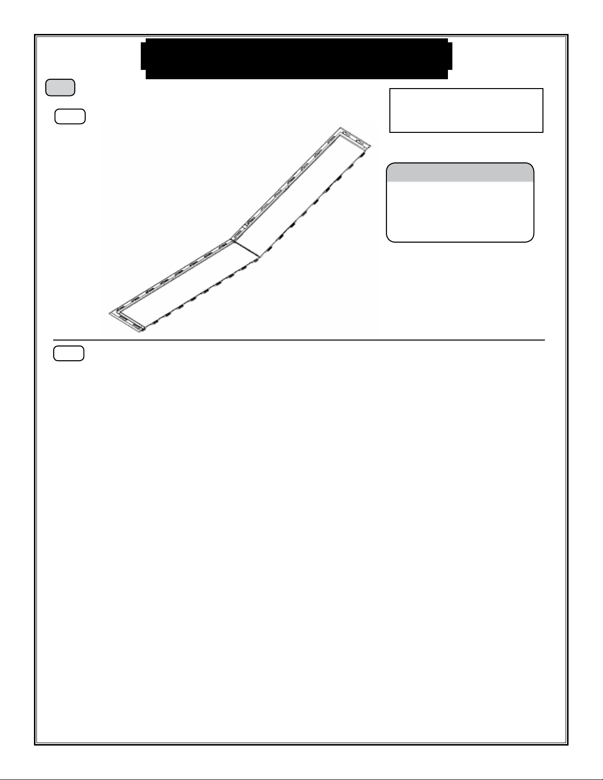
2Assemble Floor
Fit together an Outer Floor “A” Panel (AP) and an
Outer Floor “B” (AO). Hold panels at an angle to t
panels together, then lay at.
2a
CAUTION
Sharp objects may damage your
floor. If resting sharp, heavy
objects on your shed oor, place a
block of wood between the sharp
object and oor.
Fit together the second set of “A” and “B” Outer Floor Panels and then join both sets together.
2b
AO
AP
This Step uses:
2-Outer Floor “A” Panels (AO)
2-Outerr Floor “B” Panels (AP)
Before Beginning!
Remove the Parts List from the center of this manual, and organize
Shed Parts.
AO
AP AO
AP
9
Lock a Wall Panel (JF) into the front right corner position.
Have one person hold this panel while a second person
inserts the next wall panel.
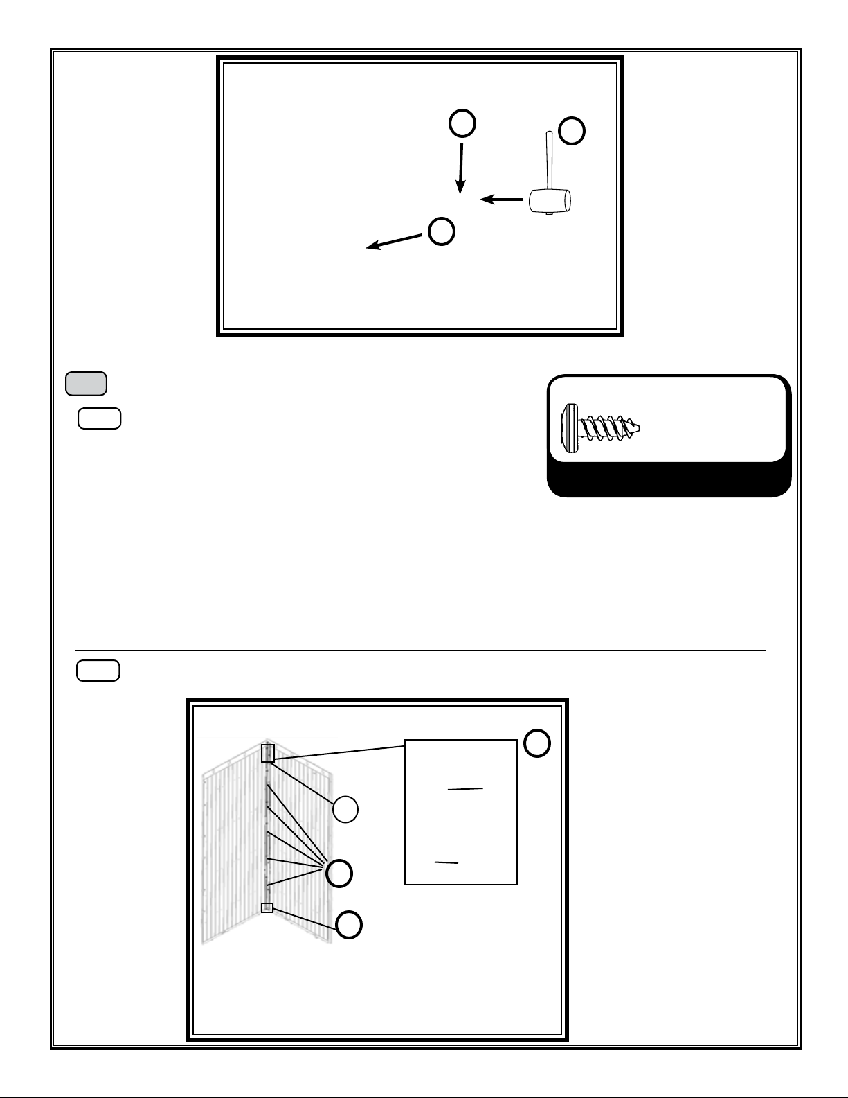
3Assemble Front Corner
3a
1
2
Inserting Wall Panels
1. Set Wall Panel Tabs into Floor Panel Slots.
2. Slide Wall Panel to the left until the Wall Panel locks into place.
3. Use a Rubber Mallet to nudge the panel into position. Be careful
not to damage the edge of the wall panel.
JF
3
1
2
Installing Corner Channels
1. Loosely insert top two screws.
2. Insert bottom two screws (tighten completely).
3. Insert remaining screws (tighten).
4. Tighten top screws.
3
Secure both Wall Panels (JF) together with a Corner Channel (AI).
3b
Hardware Bag: 1009126
Screwdriver
FE (12)
Step 3 Hardware
AI
FE
FE
4
Assembly Tip #1
Assembly Tip #2
The top of the
channel is the
end with the holes
closest to the end.
JF
10
FE (12)
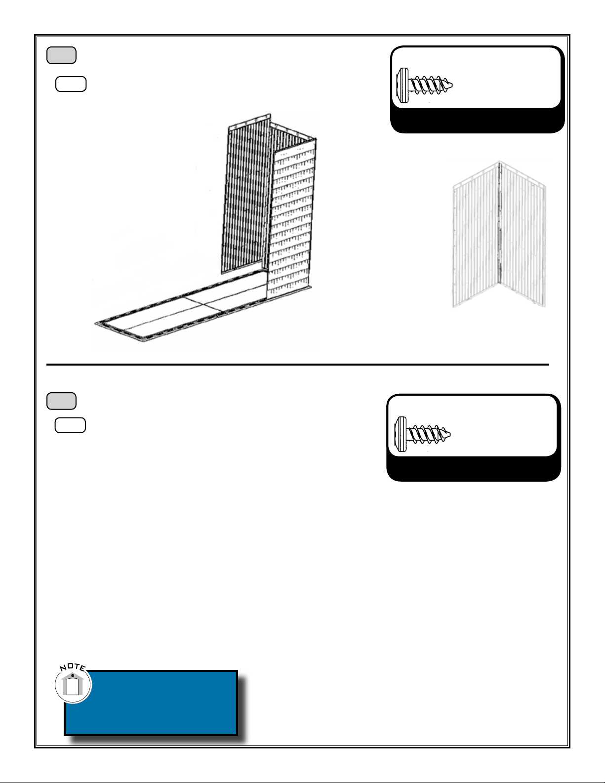
Assemble the next two Wall Panels (JF). Secure the
panels together with 1/4” Screws (FE). See Assembly
Tip #3 (p. 11).
5Assemble Back Wall
5a
Step 5 Hardware
Hardware Bag: 1009126
Screwdriver
Install the next Wall Panel (JF) at the back right corner of
the shed. Then connect with a Corner Channel (AI). See
Assembly Tip #2 (p. 9).
4Assemble Next Corner
4a FE (12)
Step 4 Hardware
Hardware Bag: 1009126
Screwdriver
Second person should
apply pressure on
opposite side of the wall
for easy insertion of
screws.
Note: e Window Wall Panel can be installed on the back wall in either of the center wall panels.
Table of contents
Other Lifetime Storage manuals

Lifetime
Lifetime 60215 User manual

Lifetime
Lifetime 136-GALLON User manual

Lifetime
Lifetime 60012 User manual

Lifetime
Lifetime 60103 User manual

Lifetime
Lifetime 619885 User manual

Lifetime
Lifetime 60059 User manual

Lifetime
Lifetime 60012 User manual

Lifetime
Lifetime 60298 User manual

Lifetime
Lifetime 60298 User manual

Lifetime
Lifetime 60209 User manual

Lifetime
Lifetime 60059 User manual

Lifetime
Lifetime 60353 User manual

Lifetime
Lifetime 6433 User manual

Lifetime
Lifetime 60372 User manual

Lifetime
Lifetime 60103 User manual

Lifetime
Lifetime 60170 User manual

Lifetime
Lifetime 60331 User manual

Lifetime
Lifetime 60209 User manual

Lifetime
Lifetime 60059 User manual

Lifetime
Lifetime 60215 User manual


