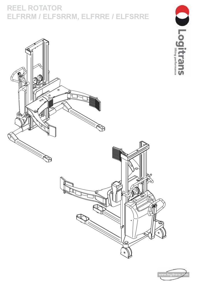
logitrans LOGIFLEX SELFR User manual

LOGIFLEX ROTATOR - SELFR / SELFSR

F:\Dok_styr\D_nummer\D144
01.02.2009
F:\Dok_styr\Blanket\B148.1-eng
Distributor:
EU DECLARATION CONFORMANCE
Manufacturer: Logitrans A/S
Hillerupvej 35
DK-6760 Ribe
Danmark
It is hereby declared that:
Machine: Productgroup: LogiexwithRotator
Type: SELFR/SELFSR
Yearofmanufacture/
Serial No:
a) Hasbeenmanufacturedinconformancewiththestipulationsofthe:
• COUNCIL DIRECTIVE no. 98/37/EC
• COUNCILDIRECTIVEno.89/336/ECC
b) Hasbeenmanufacturedinconformancewiththestipulationsofthe
standard:
• EN-1757-1
Name: Erling Pedersen
Position: Product manager
Company: Logitrans A/S
Product type declaration of:
Signature:

3
Contents
1.0 Before the rst lift................................................................................................. 4
2.0 Functions and identications .......................................................................... 5
2.1Boxholder ........................................................................................................................... 6
2.2Boxholderwithclalmps....................................................................................................... 6
3.0 How to operate the Logex with Rotator ................................................. 7
3.1 Handling of pallets............................................................................................................... 7
3.2 Emergency stop................................................................................................................... 8
3.3 Handle functions.................................................................................................................. 9
3.4 Personal safety...................................................................................................................11
3.5UseoftheRotator ............................................................................................................. 12
3.6 Adjusting of stop ................................................................................................................ 13
3.7 Setting the speed............................................................................................................... 13
3.8Resetthesettings.............................................................................................................. 13
4.0 Optimum safety ......................................................................................................14
4.1 Avoid overloads ................................................................................................................. 15
4.2 Avoid offset loads .............................................................................................................. 16
4.3Rotationrange................................................................................................................... 17
4.4 Driving loaded.................................................................................................................... 19
4.5Rotationwithload.............................................................................................................. 19
5.0 There must be a current supply.................................................................. 20
5.1 Fuses - replacement.......................................................................................................... 20
5.2 Wiring connections ............................................................................................................ 20
6.0 Long live the Logiex with Rotator ............................................................ 21
6.1 Lubrication and hydraulic oil.............................................................................................. 21
6.2 Oil change ......................................................................................................................... 22
6.3 Forks adjustment............................................................................................................... 23
6.4 Adjustment of lifting chain.................................................................................................. 23
6.5 Hydraulic pump and gear motor ........................................................................................ 24
6.6 Cleaning ............................................................................................................................ 24
6.7 Adjustment of side play...................................................................................................... 25
7.0 Adjustment of the Rotator............................................................................... 26
7.1 Tensioning the chains ........................................................................................................ 26
7.2Adjustingtheswitch........................................................................................................... 27
7.3 Lubrication......................................................................................................................... 27
8.0 Fault location key................................................................................................. 28
9.0 Good service after purchase ......................................................................... 30
9.1 Ordering spare parts.......................................................................................................... 30
9.2Warranty/Compensation.................................................................................................... 30
9.3 Service and repair ............................................................................................................. 30
9.4 Warranty ............................................................................................................................ 30
9.5Liabilityexemption............................................................................................................. 30

4
1.0 Before the rst lift...
LogiexwithRotator ismanufacturedinaccordancewithsafety
directives.
AmongothersubjectsdealtwithinthisInstruction Manual are:
ThereforepleasereadthisInstructionManualcarefully!
Proper application•
Psysicallimitationsoftheproduct•
Riskswithimproperuse•

5
1
5
4
2
3
8
7
6
10
11
12
9
13
15
16
14
2.0 Functions and identications
Remote control:
Theremotecontrolisusedwhen:
Rotatingtheforks
•
Setting tilt stop in both directions: See paragraph 3.3•
Setting rotation speed: See paragraph 3.4•
Remotecontrol
Clockwise/
counter-
clockwise
1. Safetyswitch
2. Horn
3. Lift/Lower
4. Forward/Reverse
5. Multiexfunction
6. Handle
7. Battery indicator
/hourcounter
8. Emergency stop
9. Ignition key
10. Charger plug
(externalcharger)
11.Boxholderwithclamps
12.Boxholderwithoutclamps
13.
Batterylabel(belowthecover)
14. Name plate, serial number
15. Truck number, stamped in
chassis behing the rear cover
16.Charginglamps(built-incharger)

6
380 mm
975 mm
615 mm
1210 mm
380 mm
975 mm
615 mm
1210 mm
A
B
Boxholderwith
clamps – upper
position
Boxholder
withclamps
–lowerposition
2.1Boxholder
Therotatorcanbeequippedwithoneortwosetsofboxholders,
adjustedfordifferentboxsizes.Whenlooseningthescrew(A),
theboxholdercanbemovedbetweenthetwodifferentpositions.
NOTE!Thescrewhastobetightened,beforeusingtheproduct.
Adjustingthedistance
Fork span 560mm:
•
Forboxwidthsof800,850or1000mm.
Fork span 680mm:•
Forboxwidthsof1000,1050and1200mm.
Settingofheight
Theboxholderscanbeplacedintwodifferentheights
Itisimportantthattheboxholdersareplacedapprox.ontheleveloforabove
•
the load centre of the load.
Ifpossible,usetwoboxholdersineachside•
1)Whentheweightoftheloadisbetween800and1000kg.
2)Forhighboxesorwhenthematerialoftheboxisunstable,e.g.cardboard
NOTE! Iftheboxholdershavenoclamps,theloadisnotallowedtobetiltedmore
than 60º to each side.
2.2Boxholderswithclamps
Iftheboxcanfalloff,orifithastobetiltedmorethan60º,
boxholderswithclampshavetobeused.
Boxholderswithclampscangrip,holdandrotateboxes
withdifferentheights.
Theclampsareplacedontheframeoftheboxandtightened
whentheboxisliftedup(nocontacttothefloor).
2.0 Functions and indentications

7
SELFR
SELFSR
For proper operation,
stand behind the handle.
Push/pull-raise/lower
Whenhandlingclosedpallets
-usethestraddleLogiflex!
3.1Handlingofpallets
TheLogiflexwithRotatorfunctionsasanordinarystacker,whentheforksare
placedinhorizontalposition.
3.0 How to operate Logiex w/Rotator

8
2
3
1
1
3.0 How to operate the Logiex with Rotator
Insertkey(1)andturnclockwisetoswitchoncontrolcurrentreadyfor
function activation.
Note!!!Emergencystop
(2) must not be activated.
3.2Emergencystop
The product has an emergency stop. When activating the
emergencystop,themaincurrentsupplyisswitchedoff.
The movement of the forks stops immediately•
Drivingwiththetruckstopsimmediately•
Theemergencystopisdeactivatedbyturningtheswitch•
to the right

9
3.0 How to operate the Logiex with Rotator
3.3Handlefunctions

10
Multiexfunction
This function makes it possible to drive the stacker, even though the handle is•
initsupright,brakedposition(B)
Thefunctionrequirestwo-handedoperation,i.e.itmustbeperformeddeliberately•
Thefunctionfacilitatesmanoeuvringinconnedareas.•
Multiexfunction
3.0 How to operate the Logiex with Rotator
The control functions of the stacker
arelocatedinthehandle(3).
-Thefunctionsaredependenton
thepositionsofthehandle!
Position A: Drive position
Drive current on
Brake deactivated
Position B: Stop/Brake/
EmergencyStop
Drive current off
Brake activated

11
Safetyfunction
3.0 How to operate the Logiex with Rotator
3.4Personalsafety
Thesafetyswitchontheendofthehandleensuresthattheoperatorcannotbe
trappedwhenthestackerisreversed.
Whenthesafetyswitchisactivated,thestackerwillchangedirection,move
forwardsandstop.

12
3.5UseoftheRotator
Condition: Theupperedgeoftheforksisliftedbetween400and900mm.
Theloadcanberotated355ºwithoneadjustablestopineveryside.
Note!Tocontinuethetiltfunctionfromthehorizontalposition,thetiltswitchhas
to be released and activated in the requested tilt direction.
Tolowertheforksortolifthigherthan900mm,theforkshavetobeplacedin
horizontalposition.
Softacceleration/deceleration
TheRotatorhassoftacceleration/decelerationwiththefollowingbenefits:
The rotation stops precisely
•
Thegearisprotected,becausesuddenstart/stopareminimised•
NOTE!
Theloadhastobesupported
sidewaysbeforetilting.
3.0 How to operate the Logiex with Rotator

13
A
3.6Adjustingofstop
Theforksarefactory-settostopin45º.Ifanothersettingisrequired,theRotator
can be set electronically to stop in different angles.
1) Theforksareplacedinhorizontalposition
2)ShortpressureontheswitchAactivatesthe
setting procedure. The controller gives a signal
(onebeep)
3) Theforksareplacedintherequestedangle
4) Whentheforkshavereachedtherequestedangle,
thecontrollerwillgivesignalafterthreeseconds
(onebeep),whenthepositionhasbeenstored.
The procedure is repeated to set stop in the other side
.
3.7Settingthespeed
1) Theforksareplacedinhorizontalposition
2)
Theswitchispressedthreeseconds,andtwoshort
beepswillbegiven.Theswitchisreleasedand
the speed is set by activating the remote control.
Clockwise: Increasing the speed
Counter-clockwise:Reducingthespeed
Note:Maximumtiltspeed:360º/minute.
3) Whentherequestedspeedhasbeenreached,thecontrollerwillgivesignal
afterthreeseconds(twobeeps),whenthepositionhasbeenstored.
3.8Resetthesettings
1) Theforksareplacedinhorizontalposition.
2)PressswitchA,untilfivebeepsaregiven.Theswitchisreleasedand
thecontrollerissettomaximumspeedandstopsat45°.
Plug from
remote control
SwitchA
Signal
3.0 How to operate the Logiex with Rotator

14
4.0 Optimum safety
Safetyregulations
- Neverwalkunderaraisedload!
- Beforeloweringtheforks,makecertainthatnoforeign
elementscanhinderthefreeloweringoftheforks.
- TheLogiflexisdesignedforuseonanevenandlevelfloor
- During transport the forks shall be raised as little as possible
- Transportwithraisedforksshouldbemadeovertheshortestpossible
distancesandatlowspeed
- Checkthatthechainsliftequally.Theyshallbeequallytightwhentheforks
are loaded
- Chains and chain bolts must not be damaged. Chains that have become
permanentlystretched(max.2%oforiginallength)mustbescrapped..
ATTENTION
Moving parts

15
A
C
B
4.1 Avoid overloads
Themaximumloadmustnotbeexceeded.Remember,thattheLogiflexwith
Rotatorisdesignedforevenlydistributedload,-goodsonpalletsetc.Iftheforks
are point-loaded on one side, there is a risk of bending.
NOTE!
Whendrivingwiththetruck,theforksshouldbeplacedinhorizontalposition.
Max.capacityoftheRotator/Multi-purposecarriage:1000kg/700Nm(seeload
diagram).
Load diagram
When the forks are tilted, the spatial position of the load changes. This means that
theloadcapacitythatcanbetiltedisreduced,thelargerthedistanceisbetween
load centre of the load and rotation centre.
Inordertousetheloaddiagram,thefollowingthreefactshavetobeknown:
•Thedistancefromtheupperedgeoftheforks/belowedgeoftheMulti-purpose
carrige to the load centre
•Requestedtiltdegree
•Weightoftheload
Example:
-Theloadcentreisplaced120mm(A)over
theforks/belowedgeMulti-purpose
carrige
-Tiltdegree:90º(B)
- Weight of the load: 400 kg
It appears from
the load diagram that
themaximumallowed
loadis425kg(C).
NOTE!Iftheloadcentreexceedsthealloweddistanceshownintheloaddiagram,
thereisariskthatthestackerwillturnover,whenrotating.
Load centre distance
from upper edge of
theforks/belowedge
Multi-purpose carriage.
Upperedgeforks/below
edge Multi-purpose
carriage.
4.0 Optimum safety

16
Marking
The mast lifting capacity and the corresponding centre of
gravity distance are given by the pictogram on the side of the
mast.
Theliftingcapacityofthemastisthesameasthemax.lifting
capacity of the product.
Max.liftingcapacityissetonthesafetyvalveoftheproduct.
4.2Avoidoffsetloads
Theloadmustbeevenlydistributed.Themaximumcentreofgravitydistancefrom
thefrontoftheforkmast(givenonthetruck)mustnotbeexceeded.Agreater
distance reduces the level of safety and increases the risk of tilting.
Goods on pallets, etc. must be properly secured, so that they cannot fall off during
transport,whenthetruckislifted,orwhenthetruckmustremainliftedforatime.
4.0 Optimum safety

17
4.0 Optimum safety
4.3 Rotation range
Standard version
Theloadcanberotated,whentheupperedgeoftheforksareliftedbetween
400 and 900 mm. Outside this range, the stacker functions as a standard stacker.
Bottom stop
Adjusted so that the forks are lifted 400 mm
above the floor.
Top stop
Indicates that the forks are lifted 900 mm above
the floor.
NOTE: Topstopisonlyplacedonstackerswith
lifting heights, being higher than:
920mmSELFR
890mmSELFSR

18
400
900
1450
1880
Upper
edge forks
Max.sideways
moment
SELF560x1250
Max.sideways
moment
SELF680x1250
Max.sideways
moment
SELFS560x1250with
850 mm straddle legs
Rangeofmaximumload1000kg/700Nm
of stacker in special version
Normalrangeforthemaximumload1000kg/700Nm,
fork height 400-900 mm.
Special version
Thetopstopcanbesettootherintervalsthanbetween400-900mm.
Theheightofthetopstopdependsonthewidthofthestacker,asawidestacker
canmanagealargersidewaysmovement.
E.g. Onastackerwith850mmstraddlelegs,thestopcanbeplacedata
maximumforkheightof1880mm.
4.0 Optimum safety

19
5
6
7
8
4.4 Driving loaded
Theloadcentreisneverallowedtoexceedthecentrelineofthewheels.The
drivingspeedisreducedwhenliftingtheforksabove400mm.
4.5Rotationwithload
Theloadcentreisnotallowedtobeplacedontheoutsideofthelegsofthestacker,
asthiswillcauseariskofturningover.
NOTE!Rotationisonlyallowedtotake
place, if the stacker is placed on an equal floor. Theloadisnotallowedtobe
dislocated during rotation.
Whenrotatingboxes,theoperatorneedsafull
overviewofthewholeworkingarea,sothat
the rotation movement can be stopped before
theboxtouchesthefloor,theitemsorpersons
intheworkingarea.
4.0 Optimum safety

20
40A
60A
80A
5A
10A
5.0 There must be a current supply...
5.1 Fuses - replacement
There are five fuses in the electrical circuit.
80 Amp fuse in the main supply
from battery
5 Amp fuse in the control
current circuit
10 Amp fuse for built-in charger
40 AmpfuseforRotator
60 Amp fuse for the hydraulic pump
Replacement:
Theoldfuseistoberemovedandreplacedbyanewoneofthesamesize.
Findoutwhythefusesblow!
Manyoperationaldisturbancesarecausedbybad
connectionsintheelctricalcircuit.Makesurethatthe
connections are in order.
Check connections regularly for damage at insulating caps or
bad connections at plugs etc. Verdigris must be removed from
cableplugs.Keepallscrew/nutconnectionstight.
5.2 Wirring connections
This manual suits for next models
1
Table of contents
Other logitrans Lifting System manuals
Popular Lifting System manuals by other brands

LGMG
LGMG AR65J Operation and safety manual

Dannmar
Dannmar D-12 Series user manual

Rotary
Rotary S38AK-42CAT Operation & maintenance manual

Ravaglioli
Ravaglioli KPX315WK manual

JLG
JLG 600AJ Service and maintenance manual

Dolphin
Dolphin Poollift Neptune with Transporter Operating and Product Care Instructions