Liftket B13 User manual

Operating instructions
LIFTKET B13 / LIFTKET B15
Electric chain hoists
Please do not use the hoist until all
operators have carefully read this
manual and have signed the form on
the last page.

3
Table of Contents
1Safety advice...............................................................................................................................................5
1.1 Regulations..................................................................................................................................................5
1.2 Proper use of electric chain hoists...............................................................................................................6
1.3 Application conditions..................................................................................................................................6
1.4 Prohibitions for use......................................................................................................................................7
1.5 Operating instructions..................................................................................................................................7
1.6Spare parts..................................................................................................................................................7
2Technical overview......................................................................................................................................8
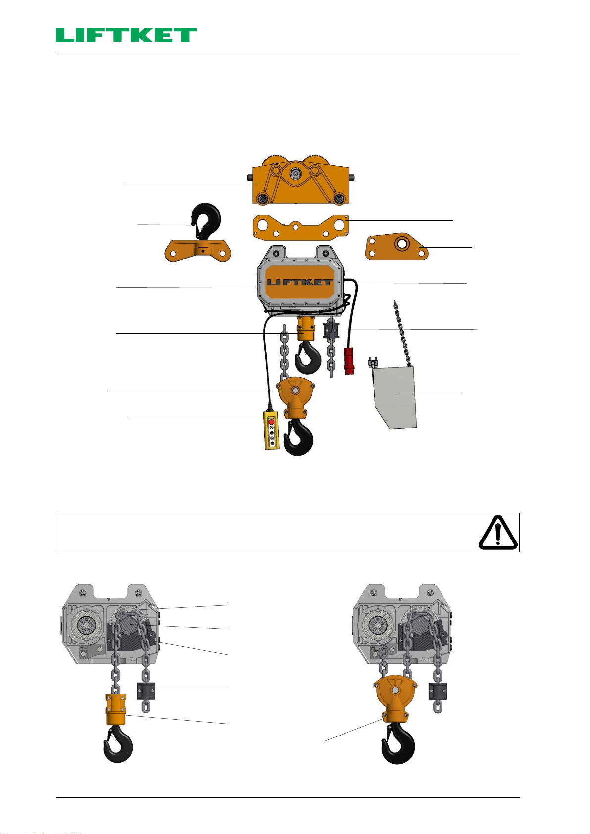
2.1 Assembly possibilities..................................................................................................................................8
2.2 Fitting the load chain....................................................................................................................................8
2.3Sectional view..............................................................................................................................................9
2.4 Explanation of type designation...................................................................................................................9
3Transportation and storage........................................................................................................................10
3.1 Transportation ...........................................................................................................................................10
3.2 Storage......................................................................................................................................................10
4Assembly...................................................................................................................................................11
4.1 Mechanical assembly ................................................................................................................................11
4.1.1 Hook tackle................................................................................................................................................11
4.1.2 Hook block.................................................................................................................................................11
4.1.3 Stationary suspension ...............................................................................................................................12
4.1.3.1 Suspension with suspension eye...............................................................................................................12
4.1.3.2 Suspension with single hole suspension eye.............................................................................................13
4.1.3.3 Suspension with suspension hook.............................................................................................................15
4.1.4 Hoisting gear with electric trolley ...............................................................................................................17
4.1.4.1 Mechanical assembly ................................................................................................................................17
4.1.4.2 Electric connection of trolleys ....................................................................................................................18
4.1.4.3 Electric control of the brake.......................................................................................................................18
4.1.5 Chain box ..................................................................................................................................................19
4.1.5.1 Mounting the chain box..............................................................................................................................19
4.1.5.2 Oversize chain box....................................................................................................................................20
4.1.6 Lift limiter...................................................................................................................................................21
4.1.7 Gear ventilation..........................................................................................................................................21
4.1.8 Schematic sketch of the load chain configuration - single fall version .......................................................22
4.1.9 Schematic sketch of the load chain configuration - double fall version......................................................23
4.1.10 Replacing the load chain, the chain guide and the chain hold-down.........................................................24
4.1.10.1 Single fall operation...................................................................................................................................24
4.1.10.2 Double fall operation..................................................................................................................................25
4.2 Electric connections...................................................................................................................................26
4.2.1 Mains connection.......................................................................................................................................26
4.2.2 Low voltage control....................................................................................................................................27
4.2.3 Electric control of the hoist brake...............................................................................................................27
4.2.4 Electric limit switch.....................................................................................................................................27
4.2.4.1 Location of electric limit switches...............................................................................................................27
4.2.4.2 Disassembling and assembling the limit switch shaft ................................................................................28
5Operation...................................................................................................................................................29
5.1 Control pendant.........................................................................................................................................29
5.2 Radio remote control .................................................................................................................................30
5.3 Load slinging .............................................................................................................................................30
6First use.....................................................................................................................................................31
6.1 General conditions and prerequisites ........................................................................................................31
6.2 Inspection before first use..........................................................................................................................31
6.3 Inspection at first use.................................................................................................................................31
6.3.1 Inspection contents....................................................................................................................................31
6.3.2 Conducting the investigation......................................................................................................................32

4
7Operation................................................................................................................................................... 33
7.1 Proper operation........................................................................................................................................ 33
7.2 Residual risks............................................................................................................................................ 33
7.2.1 Pinch hazard ............................................................................................................................................. 33
7.2.2 Burning hazard.......................................................................................................................................... 33
7.2.3 Hanging load / falling objects..................................................................................................................... 33
7.3 Working with the hoist............................................................................................................................... 34
7.3.1 Start of work.............................................................................................................................................. 34
7.3.2 Operating instructions ............................................................................................................................... 35
7.3.3 Decommissioning...................................................................................................................................... 36
8Duty rate.................................................................................................................................................... 37
8.1 Duty rate of an electric chain hoist ............................................................................................................ 37
8.1.1 Short-time duty.......................................................................................................................................... 37
8.1.2 Intermittent duty......................................................................................................................................... 38
8.1.3 Example .................................................................................................................................................... 38
8.2 Duty rate of the electric trolley................................................................................................................... 38
9Inspections................................................................................................................................................ 39
9.1 Inspection when used in compliance with DGUV Regulation 54 (BGV D8 Article 23)............................... 39
9.2 Inspection when used in compliance with DGUV Regulation 52 (BGV D6 Article 25)............................... 39
9.3 Regular inspections................................................................................................................................... 39
10 Maintenance.............................................................................................................................................. 40
10.1 Inspection and maintenance works........................................................................................................... 40
10.2 Brakes....................................................................................................................................................... 41
10.2.1 Hoist brake................................................................................................................................................ 41
10.2.1.1 Functional description ............................................................................................................................... 41
10.2.1.2 Sectional view ........................................................................................................................................... 41
10.2.1.3 Adjustment of the hoist brake.................................................................................................................... 42
10.2.2 Trolley brake.............................................................................................................................................. 43
10.2.2.1 EFB brake ................................................................................................................................................. 43
10.2.2.2 ZFB brake.................................................................................................................................................. 43
10.3 Slipping clutch........................................................................................................................................... 44
10.3.1 Brake operation......................................................................................................................................... 44
10.3.2 Sectional view ........................................................................................................................................... 44
10.3.3 Slipping clutch adjustment......................................................................................................................... 44
10.3.4 Checking the release limit of the slipping clutch during regular inspections.............................................. 45
10.4 Load chain................................................................................................................................................. 45
10.4.1 Lubricating the load chain upon first use and while in use ........................................................................ 45
10.4.2 Checking wear and tear and replacing the chain....................................................................................... 45
10.5 Measuring the wear of the load hook and replacing the load hook............................................................ 46
11 Lubrication................................................................................................................................................. 47
11.1 Drive gear.................................................................................................................................................. 47
11.2 Chain......................................................................................................................................................... 47
11.3 Hook tackle and hook block....................................................................................................................... 48
11.4 Trolley ....................................................................................................................................................... 49
12 Malfunctions.............................................................................................................................................. 50
13 Measures to be taken at the end of the theoretical safe working period.................................................... 52
13.1 Calculation of the theoretical safe working period..................................................................................... 52
13.2 Disposal .................................................................................................................................................... 52
14 EC Declaration of Conformity (sample)..................................................................................................... 53
15 Declaration of Installation (sample)........................................................................................................... 54

5
1 Safety advice
1.1 Regulations
In the German Federal Republic and in the countries of the European Union the assembly, first use, certification and
maintenance of hoisting machines is basically regulated by the following regulations and by the instructions contained
in this Operating manual.
European Directives
2006/42/EC
EC Machinery Directive
2014/30/EG
EC Directive on electromagnetic compatibility
2014/35/EG
EC Directive on electrical equipment designed for use within certain voltage limits
Regulations of the German Professional Association (Accident Prevention Regulations)
DGUV Regulation 1 (BGV A1:2009)
Principles of prevention
DGUV Regulation 3 (BGV A3:2005)
Electrical facilities and equipment
DGUV Regulation 52 (BGV D6:2000)
Cranes
DGUV Regulation 54 (BGV D8:1997)
Winches, lifting and pulling equipment
DGUV Rules 100-500 (BGR 500-2.8:2008)
Operation of work equipment
DGUV Principle 309-001 (BGG 905:2004)
Principles of checking of cranes
Harmonized Regulations
EN ISO 12100:2010
Safety of machinery
EN 14492-2:2006+A1:2009
Cranes - Power driven winches and hoists
EN 818-7:2002+A1:2008
Chains for lifting purposes; Quality Grade T
EN ISO 13849-1:2008
Safety-related parts of control systems; General principles for design
EN 60034-1:2010
Rotating electrical machines; Rating and performance
EN 60034-5:2001+A1:2007
Degrees of protection provided by the integral design of rotating electrical
machines
EN 60204-1:2006
Electrical equipment of machines, general requirements
EN 60204-32:2008
Electrical equipment; requirements for hoisting machines
EN 60529:1991+A1:2000+A2:2013
Degrees of protection provided by enclosures (IP-Code)
EN 60947-1:2007+A1:2011
Low-voltage switchgear and control gear; general statements
EN 61000-6-2:2005
Electromagnetic compatibility, immunity for industrial environments
EN 61000-6-3:2007+A1:2011
Electromagnetic compatibility, emission standard for residential, commercial
and light-industrial environments
EN 61000-6-4:2007+A1:2011
Electromagnetic compatibility, emission standard for industrial environments
EN 82079-1:2013
Preparation of for use, structuring, content and presentation
Standards and Technical Specifications
FEM 9.511:1986
Rules for the design of series lifting equipment, classification of mechanisms
FEM 9.683:1995
Selection of hoisting and travelling motors
FEM 9.751:1998
Power driven series hoist mechanisms, safety
FEM 9.755:1993
Measures for achieving safe working periods
The manufacturing plant accepts no warranty obligation whatsoever upon non-compliance with any of the instructions
of the above safety regulations or of this Operating manual.
In other countries, the respective national regulations are to be considered.

6
1.2 Proper use of electric chain hoists
Electric chain hoists are designed to lift and to lower loads vertically and to travel horizontally with lifted loads (using
trolleys).
The manufacturer's liability for losses due to the improper use of electric chain hoists is excluded. All risks are borne
by the operator.
Electric chain hoists may only be operated by persons who have been trained for this by the operator. They must be
familiar with these Operating instructions, which should be available at all times. Do not operate the electric chain
hoist until all operators have thoroughly familiarised themselves with the contents of these Operating instructions, and
have acknowledged this by signing the designated field on the rear cover of this booklet.
CAUTION
It is also the responsibility of the operator to ensure that all suspension points of the
electric chain hoist are designed to safely withstand the forces exerted. The electric
chain hoist may only be operated if it has been suspended as specified and if thereby it
is ensured that during the lifting process at any time the outgoing chain can safely run
out of the hoist due to its own weight. Disregarding the above instruction will cause the
chain to jam and thereby the hoist to be damaged.
ATTENTION
Prior to first use please make sure that all electrical connections were made as
specified, that all wires are intact, and that power to the device can be disconnected
from the mains using a master separator switch.
Only qualified persons (experts) may perform works on the electric chain hoist, and only
after the master switch of the crane has been switched off and locked, and the work
area has been secured.
These Operating instructions serve the safety of the works performed on and with the electric chain hoist. The below
safety advice must be observed under all circumstances. When compiling these safety instructions we did not strive
for completeness. You should keep this manual clean, complete and in a legible condition.
Should you have any questions or problems, please contact your competent local representative.
NOTE
The manufacturer does not accept any responsibility for damages or malfunctions
due to any of the following causes:
•Improper operation;
•Voluntary modifications to the hoisting device;
•Unprofessional work on and using the hoisting device;
•Operational errors;
•Non-compliance with these Operating instructions.
1.3 Application conditions
Application range
Notes
Temperature
–20°C ... +40°C
Coil heating (option)
Air humidity
maximum 85%
May not fall below the dew point
Electric protection
IP 54
IP 55 (option)
Insulation class
F (155°C)
Use at altitude
Maximum 1,000 metres above sea level
(NN)
NOTE
For different application conditions or when used in aggressive environments please
contact the manufacturer.

7
1.4 Prohibitions for use
ATTENTION
Non-compliance with the following prohibitions for use may cause fatal or severe bodily
harm (invalidity).
It is prohibited:
•To transport persons in any way whatsoever
•To operate in inching mode
•To use of the slip clutch in an operational way (emergency end-position limitation)
•For people to stay underneath the load (except for designs in accordance with DGUV V17 (BGV C1))
•To move loads heavier than the nominal load;
•To pull loads that are tilted or to drag loads;
•To tear off loads;
•To remove the cover of vessels which are under vacuum;
•To move a trolley by pulling the control pendant or the control cable, even if these are;
•To use the chain as a suspension or to tie the load;
•To operate with a chain that is longer than indicated on the chain box;
•To start use prior to inspection by a trained specialist or expert;
•To carry out repairs without specialist knowledge;
•Please carry out repairs only when the mains supply switch is off and secured, and when the hoist is not loaded;
•To exceed the maximum permitted switch-on duration;
•To operate the hoist once the deadline for the periodic health and safety inspection has been exceeded.
1.5 Operating instructions
Caution
Non-compliance with the following prohibitions for use may cause damage to property
and light or medium bodily injury.
•The load may only be moved once it has been properly suspended on the hook and if there are no persons
located within the danger zone (DGUV Specification 54 (BGV D8)).
•The load must be placed vertically under the electric hoist before lifting.
•Do not turn the chain over edges.
•Do not lower the double fall hook enough to allow the chain to become slack.
•Consult the manufacturer if the hoist is to be used in an aggressive environment
•Consult the manufacturer when transporting red-hot melts or similar hazardous materials.
•After an actuation of the emergency stop button, the cause of its use must be eliminated by expert personnel. The
emergency stop button may only be reset afterwards.
•Operators should always use the lowest available speed when lifting loads lying on a plane. Loose suspensions
must first be tightened before lifting.
•When operating the hoist at a range of heights reachable by hand, do not touch the part where the chain enters
the unit, and take other proper safety measures to avoid this.
1.6 Spare parts
NOTE
Use only original fastening elements, replacement part and accessories. The
manufacturing plant accepts liability only for these.
The manufacturing plant excludes all liability for damages due to the use of non-original
parts and accessories.

8
2 Technical overview
2.1 Assembly possibilities
Based on the building block principle that enables easy assembly, the system enables the unproblematic conversion
of the electric chain hoist from a single chain fall version to a double chain fall version. The hoists can be used in a
fixed design, with manual or electric trolleys. Large lifting and operating heights are possible.
Electric trolley
Hook suspension
Hoisting gear
Hook tackle
Hook block
Control pendant
Suspension eye
Single hole
suspension eye
Mains cable
with switch
Lift limiter
Chain box with
safety chain
Diagram No. 1: Assembly possibilities
2.2 Fitting the load chain
CAUTION
Use only original chains from the manufacturer! These chains meet the high
requirements for load and service life.
Single fall version
Double fall version
Chain hold-down
Chain driving shaft
Chain sprocket
Chain guide
Lift limiter
(end-position stop)
Hook tackle
Hook block
Diagram No. 2: Position of the load chain

9
2.3 Sectional view
1
Casing
2
Drive gear
3
Gear cover
4
Load chain
5
Chain guide
6
Chain hold-down
7
Low voltage control
8
Cover for low voltage control
9
Motor with brake unit and fan
10
Fan cover
3 2 1 9 10
Diagram No. 3: Electric chain hoist sectional view
2.4 Explanation of type designation
Example: Model 13
Type 12500 / 2 - 2.8 / 0.7
Slow lifting speed in m/min
Main lifting speed in m/min
Number of falls
Capacity in kg
The technical data are contained in the documentation provided with the hoist.
7
8
6
5
4

10
3 Transportation and storage
CAUTION
Transportation works should be performed by trained personnel only.
The manufacturing plant does not accept any liability whatsoever for damages due to
unprofessional transportation or storage.
3.1 Transportation
Prior to delivery we have checked the hoist and its accessories and have packaged it properly.
Following receipt please check the goods for shipment defects and for completeness, including also the
documentation.
CAUTION
Do not transport hoists on damaged pallets.
Do not throw or overturn hoists.
Transportation with damaged transportation fasteners is prohibited.
Do not expose hoists to rain and moisture.
3.2 Storage
Store hoists in a dry and clean condition under the following conditions:
•Indoors storage
•Storage temperature range between -20°C ... +40°C
•Do not allow large swings in temperature and corrosive environments
•Maximum air humidity: 85%
•No aggressive environment
•No direct sun radiation

11
4 Assembly
4.1 Mechanical assembly
4.1.1 Hook tackle
The hook tackle is used to attach loads for hoists of a single fall version.
Pursuant to DGUV Regulation 54 (BGV D8 Article 24) assembly must be carried out by a trained specialist.
Hook casing
Allen screws
with spring washers
Hook casing cover
Load hook, complete
(with hook nut, thrust ball
bearing, and safety latch)
Diagram No. 4: Hook tackle assembly
CAUTION
During maintenance check the condition of the hook (for wear and centre punch
spacing).
Also check the condition of the hook bearing, of the safety latch and of the hook nut
safeguard. If required, clean and grease the axial bearing. The hook nut of the load
hook of the hook tackle is secured by a spring-pin inserted at a right angle to the shaft.
For the assembly of the hook tackle please tighten the connection screws using the following torque values:
Max. load capacity [kg]
Screws
Quantity
Tightening torque [Nm]
Hook tackle for chain 16×45
6300
M12×60 DIN 912-8.8
4
50
Hook tackle for chain 17.3×48
7500
M12×60 DIN 912-8.8
4
50
Table No. 1: Tightening torques for screw connections
4.1.2 Hook block
The hook block is used to attach the load in the double fall version of hoists.
Pursuant to DGUV Regulation 54 (BGV D8 Article 24) assembly must be carried out by a trained specialist.
Casing
Allen screws
with self-locking nut
Chain sprocket
Shaft with sliding bearing
Safety pin
Load hook, complete
(with hook nut, thrust ball
bearing and safety latch)
Diagram No 5: Hook block assembly

12
For the assembly of the hook block please tighten the connection screws using the following torque values:
Max. load capacity [kg]
Screws
Quantity
Tightening torque [Nm]
Hook block for chain 16×45
12500
M12×50 DIN 912-8.8
4
50
Hook block for chain 17.3×48
15000
M12×50 DIN 912-8.8
4
50
Table No. 2: Torques values for screw connections
CAUTION
During maintenance check the condition of the hook (for wear and centre punch spacing).
Also check the condition of the chain sprocket, of the safety latch and of the hook nut safe-
guard.
If required, clean and grease the axial bearing.
The hook nut of the load hook of the hook block is secured by a spring-pin inserted at a
right angle to the shaft.
4.1.3 Stationary suspension
4.1.3.1 Suspension with suspension eye
CAUTION
Do not use other bolts than the original suspensions bolts. In particular, do not use
screws to connect the electric chain hoist to its suspension elements.
NOTE
Use the two bolts to fasten the provided suspension eye to the boreholes on the case of
the hoist configured for this purpose. Place the washer discs onto the bolts and secure
the bolts with the self-locking nuts.
Suspension eye
with marking
Self-locking nut
Washer disc
Suspension borehole
Bolt
Diagram No 6: Suspension with suspension eye

13
4.1.3.2 Suspension with single hole suspension eye
CAUTION
Do not use other bolts than the original suspensions bolts. In particular, do not use
screws to connect the electric chain hoist to its suspension elements.
NOTE
Use the two bolts to fasten the provided single hole suspension eye to the boreholes on
the case of the hoist configured for this purpose. Place the washer discs onto the bolts
and secure the bolts with the self-locking nuts.
Single hole suspension eye
with marking
Self-locking nut
Washer disc
Borehole on the casing
of the electric chain hoist
Bolt
Diagram No 7: Suspension with single hole suspension eye
CAUTION
Assemble the single hole suspension eye to ensure that the centre of the suspension
hole falls in line with the centre of gravity of the load in case of both single and double
fall versions.
Of the symbols referring to the single fall or double fall versions (hook tackle and hook
box) the marking corresponding to the actual hoist version must be on the side of the
chain box.
When changing the number of falls for a hoist fitted with a single-hole suspension eye
the suspension eye is to be disassembled from the hoist casing. After this it should be
turned at an angle of 180° and re-assembled again.

14
Single hole suspension eye
Marking, hook tackle symbol
Marking on the hoist gear
Load centre of gravity with single fall
operation
Diagram No 8: Position of single hole suspension eye with single fall operation
Single hole suspension eye
Marking, hook box symbol
Marking on the hoist gear
Load centre of gravity with double fall
operation
Diagram No. 9: Position of single hole suspension eye with double fall operation

15
4.1.3.3 Suspension with suspension hook
CAUTION
Do not use other bolts than the original suspensions bolts. In particular, do not use
screws to connect the electric chain hoist to its suspension elements.
NOTE
Use the two bolts to fasten the suspension hook to the boreholes configured on the
hoist casing. Place the washer discs onto the bolts and secure the bolts with the self-
locking nuts.
Hook suspension
Self-locking nut
Washer disc
Borehole on the casing of
the electric chain hoist
Bolt
Diagram No 10: Hook suspension for the chain hoist
NOTE
If desired, the hook suspension can also be delivered in a non-rotating version (option).
CAUTION
The suspension hook is to be rotated when changing the number of chain falls.
Assemble the suspension hook to ensure that the centre point of the load hook of the
suspension hook falls in line with the centre of gravity of the load in case of both single
and double fall versions.
Of the symbols referring to the single fall or double fall versions (hook tackle and hook
box) the marking corresponding to the actual hoist version must be on the side of the
chain box.
When changing the number of falls for a hoist fitted with a suspension hook the
suspension eye is to be disassembled from the hoist casing. After this the suspension
hook is to be rotated at an angle of 180° and re-assembled in the boreholes of the hoist
configured for this purpose.

16
Hook suspension
Marking, hook tackle symbol
Marking on the hoist gear
Load centre of gravity with single fall
operation
Diagram No 11: Position of hook suspension with single fall operation
Hook suspension
Marking, hook box symbol
Marking on the hoist gear
Load centre of gravity with double fall
operation
Diagram No 12: Position of hook suspension with double fall operation

17
4.1.4 Hoisting gear with electric trolley
NOTE
All trolleys are suitable for
•Thin beams in accordance with DIN 1025 and Euronorm 24-62;
•Medium I-beams in accordance with DIN 1025;
•Wide I-beams in accordance with DIN 1025.
CAUTION
At the height of the centre of the bumpers install girder limit stops at the ends of the
girder. Additionally, as an option, a version with an electric travel end position switch
can also be ordered. It is the responsibility of the client to configure the switch pins
necessary for this.
The electric trolley of type B13 and B15 hoists is not suitable for girder bends!
Limit stop
Suspension eye
Spacing washers
Trolley motor
Low voltage control
Trolley pin
Diagram No 13: Hoisting gear with electric trolley
Explanation of trolley type designation:
Type example:
EF
N
/
12500
4+16
EF –Electric trolley
N, S1 flange width
Capacity in kg
Electric trolley travel speed
4.1.4.1 Mechanical assembly
NOTE
The two suspension bolts are to be fastened to the lateral board of the trolley so as to
allow a clearance of about two millimetres between the running wheel flange and the
girder flange. The width of the trolley is adjusted by inserting spacing washers
symmetrically.
Diagram No. 14: Adjusting the width of electric trolley
The suspension eye is mounted between the safety bushes on the trolley connecting bolts. There is a safety pin on
one of the lateral boards to ensure that the trolley can be mounted in the right position. The M36x1.5 nut of the trolley
bolt is to be tightened with a torque spanner using a torque of 250 Nm. For the mounting of the hoist there are two
suspension bolts with diameters of ø36. The suspension bolts are secured by M22x1.5 DIN 985 self-locking nuts.

18
NOTE
After assembly, there must still be freedom of movement between the hoist and the
trolley in the direction of the arrows shown on the diagram.
Diagram No. 15: Freedom of movement between the hoist and the trolley
4.1.4.2 Electric connection of trolleys
The contactors of the low voltage control are located in the control box of the trolley motor. This box is attached to the
side plate of the trolley on the motor side using two M8x16 DIN 933 hexagonal bolts. It is the responsibility of the
Client to connect the connecting cable between the trolley control box and the trolley motor in accordance with the
circuit diagram.
The connecting cable leading from the trolley control box is to be connected within the electric connection space of
the electric chain hoist in accordance with the circuit diagram. After electric connection check that all functions of the
hoist and of the trolley are operating correctly.
Trolley control box
Connecting cable chain
hoist - trolley
Low voltage control in the hoist
Connecting cable chain
hoist - trolley
Control pendant cable
Mains connecting cable
Contactor box trolley motor
Connector control box - trolley motor
connection box
Contactor box on lifting motor
Connecting cable chain hoist -
trolley
Control pendant cable
Diagram No 16: Electric connection of trolleys
4.1.4.3 Electric control of the brake
The brake is fed by a rectifier circuit. The brake operates on the quiescent current principle. Upon a cessation of
voltage, the brake acts automatically and the travelling motion is stopped.

19
4.1.5 Chain box
4.1.5.1 Mounting the chain box
There is a bracket fastened with two M12x55 DIN 912 allen screws on the bottom of the electric chain hoist casing
used to fasten the chain box. Hang the chain box into its place using the M20x180 DIN 931 screw and secure it by
screwing on the self-locking nut.
To secure the chain box into place and to adjust its position, mount the securing chain as follows:
•Insert the upper end of the securing chain into the chain pocket configured on the hoist casing for this purpose
and secure it with the M8x30 DIN 933 hexagonal bolt and washer.
•Fit the last chain link of the lower end of the securing chain (7x22) into the opening configured for this purpose on
the chain box and fasten it with the M8x35 DIN 931 hexagonal bolt and self-locking nut.
•Ensure that the securing chain is tight and not twisted after assembly.
Chain box fastening bolt
with self-locking nut
Chain box
Fastening the suspension chain
on the electric chain hoist
Suspension chain
Fastening the suspension chain
on the chain box
Diagram No. 17: Mounting the chain box
Hexagonal bolt
with M8×30 DIN 933 washer
Hexagonal bolt
with M20×180 DIN 931
self-locking nut
Diagram No 18: Detail drawings for mounting
ATTENTION
Ensure that the available chain box is sufficient for the given chain length (see the
chain size and maximum capacity marking indicated on the chain box).
Insert the chain end with lift limiter loosely into the chain box.
Do not exceed the specified maximum chain length!
NOTE
Take care for load holding elements not to be in contact with or not to hit the chain
box.

20
4.1.5.2 Oversize chain box
In case of oversize chain boxes (with chain lengths > 40m) the chain box must be relieved of strain.
NOTE
With fixed applications using a suspension hook or a single hole suspension eye the
operator must fashion a suspension point to fasten the suspension chain.
The length of the suspension chain is to be adjusted to the local circumstances when
mounting the electric chain hoist. Meanwhile please take care for the chain box to be
suspended approximately vertically and not to reach into the path of the hook.
If the electric chain hoist is mounted on a trolley, then the chain box must be relieved of its strain using an additional
tandem trolley.
Electric chain hoist with suspension hook Electric chain hoist with electric trolley
and tandem trolley
Diagram No 19: Mounting of an oversized chain box
This manual suits for next models
1
Table of contents
Other Liftket Chain Hoist manuals
Popular Chain Hoist manuals by other brands

Edbro
Edbro CX 11 Operator's manual

Ingersoll-Rand
Ingersoll-Rand CL125K Product information

Coffing Hoists
Coffing Hoists ELC Series Operating, Maintenance & Parts Manual

Zephyr
Zephyr ZGS-12000-2 Operation and maintenance manual

REMA
REMA DG10 Series Manufacturer's instruction and information

POWERTEX
POWERTEX PGT-S2 user manual