Liftket STAGEKET User manual

Operating instructions
STAGEKET
Electric chain hoists
Please do not use the electric chain
hoist before all operators have
carefully read and understood this
manual and signed the form on the
rear cover.

2
LIFTKET Hoffmann GmbH
Dresdener Straße 64-68
04808 Wurzen / Germany
+49-3425-89 24-0
+49-3425-89 24-99
www.liftket.de
Ho 08/2017 englisch
Original operating instructions
© 2017

3
Contents
1Safety instructions .......................................................................................................................................5
1.1 Regulations..................................................................................................................................................5
1.2 Advice for the use of electric chain hoists....................................................................................................6
1.2.1 Design according to DGUV V54 (BGV D8)..................................................................................................6
1.2.2 Additional requirements when designed according to DGUV V17 (BGV C1) ..............................................7
1.3 Prohibitions of use.......................................................................................................................................7
1.4 Directions for use.........................................................................................................................................7
1.5 Visible damages ..........................................................................................................................................8
1.6 Special features of electric chain hoists according to DGUV V17 (BGV C1)...............................................8
1.6.1 Prohibitions of use.......................................................................................................................................8
1.6.2 Moving of loads............................................................................................................................................8
1.6.3 Persons underneath suspended loads ........................................................................................................8
1.6.4 Types of loads .............................................................................................................................................8
1.6.5 Attaching lights or other equipment to the electric chain hoists ...................................................................9
1.7 Spare parts..................................................................................................................................................9
2Technical overview......................................................................................................................................9
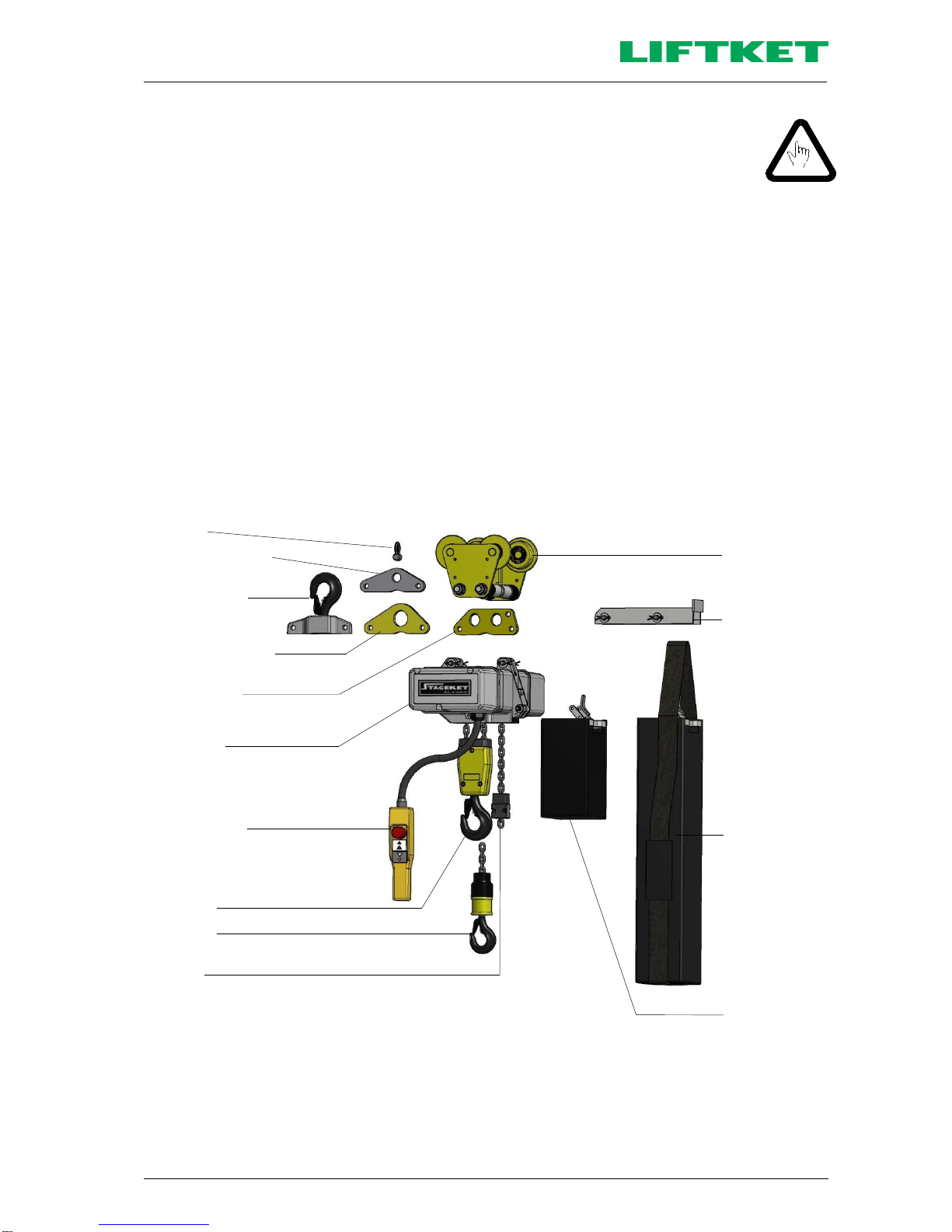
2.1 Assembly.....................................................................................................................................................9
2.1.1 Standard version and version MB in upright use according to DGUV V54 (BGV D8)..................................9
2.1.2 Version MB in inverted use according to DGUV V54 (BGV D8)................................................................10
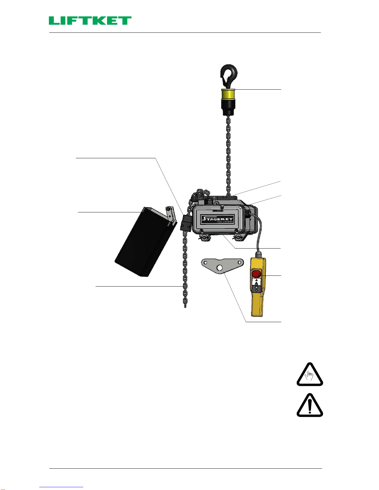
2.1.3 Version SB in upright use according to DGUV V17 (BGV C1)...................................................................11
2.1.4 Further completion possibilities .................................................................................................................11
2.2 Explanation of type designation.................................................................................................................11
2.3 Sectional view............................................................................................................................................12
2.4 Illustration of the load chain configuration..................................................................................................13
3Assembly...................................................................................................................................................13
3.1 Mechanical assembly ................................................................................................................................13
3.1.1 Hook tackle................................................................................................................................................13
3.1.2 Hook block.................................................................................................................................................14
3.1.3 Stationary electric chain hoist....................................................................................................................15
3.1.3.1 Hoist suspension with suspension eye ......................................................................................................15
3.1.3.2 Hoist suspension with single hole suspension eye....................................................................................16
3.1.3.3 Hoist suspension with hook suspension....................................................................................................17
3.1.4 Gear ventilation..........................................................................................................................................18
3.1.5 Chain box ..................................................................................................................................................18
3.1.5.1 Mounting the chain box..............................................................................................................................18
3.1.5.2 Oversize chain box....................................................................................................................................19
3.1.6 Assembling the load chain in single fall version.........................................................................................20
3.1.7 Assembling the load chain in double fall version .......................................................................................21
3.1.8 Replacing the load chain, the chain guide and the hold down...................................................................22
3.1.9 Lift limiter...................................................................................................................................................22
3.2 Electric connections...................................................................................................................................22
3.2.1 Mains power ..............................................................................................................................................22
3.2.2 Operating voltages.....................................................................................................................................23
3.2.3 Direct control .............................................................................................................................................24
3.2.4 Low voltage control....................................................................................................................................24
3.2.5 Electrical limit switches for lift limiting........................................................................................................25
3.3 Configuration of electric chain hoists according to DGUV V17 (BGV C1)..................................................25
3.4 Limit switches in upright use......................................................................................................................26
3.5 Limit switches in inverted use....................................................................................................................26
3.6 Operation and emergency limit switches ...................................................................................................26
3.6.1 Gear limit switches.....................................................................................................................................26
3.6.2 External emergency limit switches.............................................................................................................27
3.7 Incremental encoder..................................................................................................................................28
3.8 Mechanical underload protection...............................................................................................................29
3.9 Electronic overload and underload protection............................................................................................30
3.10 Control pendant.........................................................................................................................................32
4Electric chain hoist with trolley...................................................................................................................33
4.1 Types of trolleys.........................................................................................................................................33
4.2 Permissible curve radius............................................................................................................................33
4.3 Horizontal movement of electric chain hoists.............................................................................................34
4.4 Attachment of lightening devices to electric chain hoists...........................................................................34

4
4.5 Mechanical assembly................................................................................................................................ 34
4.5.1 Assembly position of the trolley on the electric chain hoist........................................................................ 34
4.5.2 Assembly of the trolley with two connecting bolts...................................................................................... 35
4.5.3 Assembly of the trolley with tandem trolley ............................................................................................... 35
4.5.4 Assembly of the trolley with one connecting bolts..................................................................................... 36
4.6 Electric trolleys with counterweight............................................................................................................ 36
4.7 Electric connection of electric trolleys........................................................................................................ 36
5Initial operation.......................................................................................................................................... 36
5.1 Initial operation according to DGUV V54 (BGV D8) .................................................................................. 36
5.2 Initial operation according to DGUV V17 (BGV C1) .................................................................................. 36
6Tests ......................................................................................................................................................... 37
6.1 Test when used according to DGUV V54 (BGV D8) §23 - Winches, lifting and pulling equipment ........... 37
6.2 Test when used according to DGUV V52 (BGV D6) §25 - Cranes............................................................ 37
6.3 Regular tests............................................................................................................................................. 37
6.4 Additional tests according to DGUV V17 (BGV C1) .................................................................................. 37
7Maintenance.............................................................................................................................................. 38
7.1 Maintenance and checks........................................................................................................................... 38
7.2Single brake .............................................................................................................................................. 39
7.2.1 Description of the single brake.................................................................................................................. 39
7.2.2 Replacement of the brake ......................................................................................................................... 39
7.3 Double brake SK 02../... and SK03../......................................................................................................... 40
7.3.1 Description of the double brake................................................................................................................. 40
7.3.2 Replacement of the brake ......................................................................................................................... 40
7.4 Double brake SK 05../... and SK07../......................................................................................................... 41
7.4.1 Description of the double brake................................................................................................................. 41
7.4.2 Replacement of the brake ......................................................................................................................... 42
7.5 Electric control of the brake....................................................................................................................... 43
7.6 Troubleshooting on the brake.................................................................................................................... 43
7.7 Functional check of the brake.................................................................................................................... 43
7.7.1 Operation and emergency brake (double brake)....................................................................................... 44
7.8 Safety sliding clutch................................................................................................................................... 45
7.8.1 Construction of safety sliding clutch.......................................................................................................... 45
7.8.2 Adjustment of friction torque at the safety sliding clutch............................................................................ 46
7.8.3 Checking the release limit of the sliding clutch during regular inspections................................................ 46
7.9 Assembly and disassembly of the brake-clutch assembly group............................................................... 47
7.10 Load chain................................................................................................................................................. 47
7.10.1 Lubrication of the load chain before initial operation and during operation................................................ 47
7.10.2 Testing of wear and replacement of the load chain................................................................................... 48
7.11 Measuring wear and replacing load hook.................................................................................................. 48
7.12 Maintenance work on the trolleys.............................................................................................................. 49
7.12.1 Construction of the brake of the electric trolley.......................................................................................... 49
8Duty rate of an electric chain hoist ............................................................................................................ 50
8.1 Short time duty.......................................................................................................................................... 50
8.2 Intermittent duty......................................................................................................................................... 51
8.3 Example .................................................................................................................................................... 51
9Duty rate of the electric trolleys................................................................................................................. 51
10 Strainer clamp for the control cable........................................................................................................... 52
11 Lubricants / Auxiliary materials.................................................................................................................. 52
11.1 Gear.......................................................................................................................................................... 52
11.2 Chain......................................................................................................................................................... 53
11.3 Hook block and hook tackle....................................................................................................................... 54
11.4 Trolley ....................................................................................................................................................... 54
12 Measures to be taken at the end of the S.W.P.......................................................................................... 54
13 Example of Declaration of Conformity....................................................................................................... 55
14 Example of Declaration of Incorporation ................................................................................................... 56

5
1 Safety instructions
1.1 Regulations
The following regulations and all recommendations of this manual serve as basis for assembly, installation,
certification and maintenance of electric chain hoists, within Germany and within the area of the European
community. For countries other than mentioned, local legislation and directives may apply in addition to the
regulations as stated in this manual (German/European). Please pay particular attention to the rules for the
prevention of accidents and the statutory regulations.
European Regulations
2006/42/EC
EC-Machine directive
2014/30/EG
EC-Directive relating to electromagnetic compatibility
2014/35/EG
EC-electrical equipment designed for use within certain voltage limits
BGV accident prevention regulations
DGUV Vorschrift 3 (BGV A1)
Principles of prevention
DGUV Vorschrift 3 (BGV A3)
Electrical facilities and equipment
DGUV Vorschrift 52 (BGV D6)
Accident prevention regulation for use in crane systems
DGUV Vorschrift 54 (BGV D8)
Accident prevention regulation for electric winches, lifting and pulling equipment
DGUV Regel 100-500 (BGR 500)
Hoisting accessories
DGUV Grundsatz 309-001 (BGG 905)
Principles for crane inspections
Harmonized regulations
DIN EN ISO 12100:2010
Safety of machinery; Basic terminology, methodology
DIN EN 14492-2:2006+A1:2009
Cranes - Power driven winches and hoists
DIN EN 818-7:2002+A1:2008
Short link chain for lifting purposes; Fine tolerance hoist chain, Grade T
DIN EN ISO 13849-1:2008
Safety of machinery - Safety-related parts of control systems; General principles for
design
DIN EN 60034-1:2010
Rotating electrical machines; Rating and performance
DIN EN 60034-5:2001+A1:2007
Rotating electrical machines; Degrees of protection provided by the integral design of
rotating electrical machines
DIN EN 60204-1:2006
Electrical equipment of machines, General requirements
DIN EN 60204-32:2008
Electrical equipment of machines; Requirements for hoisting machines
DIN EN 60529:1991+A1:2000
Degrees of protection provided by enclosures (IP-Code)
DIN EN 60947-1:2007+A1:2011
Low-voltage switchgear and control gear
DIN EN 61000-6-2:2005
Electromagnetic compatibility, Immunity for industrial environments
DIN EN 61000-6-3:2007+A1:2011
Electromagnetic compatibility, Emission standard for residential, commercial and light-
industrial environments
DIN EN 61000-6-4:2007+A1:2011
Electromagnetic compatibility, Emission standard for industrial environments
DIN EN 82079-1:2013
Preparation of instructions for use - Structuring, content and presentation
Regulations and technical specifications
FEM 9.511:1986
Rules for the design of series lifting equipment; Classification of mechanisms
FEM 9.683:1995
Series lifting equipment; Selection of hoisting and travelling motors
FEM 9.751:1998
Series lifting equipment; Power driven series hoist mechanisms; Safety
FEM 9.755:1993
Serial hoist units; Measures for achieving safe working periods
The producers guarantee depends on consideration of these regulations and of operating instructions.
Other national regulations are valid for countries outside of the European community.

6
1.2 Advice for the use of electric chain hoists
1.2.1 Design according to DGUV V54 (BGV D8)
Electric chain hoists are designed to lift and to lower loads vertically and to travel horizontally with those lifted loads
(with trolleys).
Any other use is not considered to be proper. Manufacturer does not take responsibility for any improper use and the
risk is on the operator’s responsibility.
The use of the electric chain hoist in an aggressive environment is not allowed without permission of the
manufacturer.
To this effect, it may be necessary to make certain components from different materials.
The electric chain hoist can only be operated by personnel, who have complete knowledge of this manual, and have
unhindered access to it. Do not operate the electric chain hoist until all operators have thorough knowledge of this
manual, and acknowledge that by signing the allocated field on the rear cover of this brochure.
If properly used, the modern design of the electric chain hoists guarantees safety and economic
operation.
The safety friction clutch is located outside of the load path, which enables stopping the load without
putting strain on the clutch. The force of the brake acts via a form-locked join on the gear and therefore
it will be directly transmitted on the load.
Before first use make sure, that all electrical wires are connected in accordance with the instructions,
that all wires are without damages and that the whole equipment could be switched off by a main
switch. It is the responsibility of the operator to make sure that all suspension points of the hoist are
designed to safely withstand the dynamic forces caused by the lifting equipment.
The chain hoist can only be used when it is suspended according to specification and the outgoing
chain can leave the hoist safely, by its own weight, in the relevant direction.
Therefore the container for the dead end of the chain outside the hoist must be big enough to allow the
chain to come out.
If not, the chain can be trapped inside the hoist and can break the casing of the hoist.
Maintenance work on electric chain hoists has to be carried out by trained and authorised people only.
The main switch has to be switched off and the working area is to be secured beforehand.
Authorised people have to have a theoretical training as well as experience in the field of winches, lifting and pulling
equipment or cranes. They have to possess an excellent knowledge of the relevant work safety regulations,
directives, and general accepted rules of lifting techniques, which enables them to decide whether the lifting
equipment is in a safe working condition or not.
Any maintenance work and inspections are to be entered into the crane inspection book (e.g. brake or clutch
adjustments).
This manual will tell you how to operate the hoist and how to handle its suspension or its loads safely. The following
safety advices have to be observed. The safety instructions may not be complete for each mode of use. If there are
any questions or problems contact the manufacturer or our local representative.
This Operating Instructions should always be in a complete and fully readable condition.
No responsibility is taken for damages and operating troubles due to the following reasons:
•improper use
•unauthorised modification of the drive system
•unworkmanlike work done on the system and with the system
•operating errors
•Failure to use the product as instructed in the manual

7
1.2.2 Additional requirements when designed according to DGUV V17 (BGV C1)
The electric chain hoists in the design ‚SB‘(with 2 brakes and half load capacity) are subject to requirements of
DGUV V17 (BGV C1).
The operators have to be well trained in order to make them aware about the special requirements,
resulting from stage and studio use of chain hoists according to DGUV V17 (BGV C1). The operation
instructions have to be read carefully by the operators and they shall sign a form stating that they have
got the information.
1.3 Prohibitions of use
•Do not use the chain hoist to carry people. It is strictly prohibited.
•Do not use the chain hoist in inching mode (fast switching on / off of functions).
•Do not permanent run against the rubber buffers of the lowest and highest hook position
(ultimate safety limit for emergency only).
•Do not use the chain hoist with people being underneath the load.
This does not apply to electric chain hoists in accordance with DGUV V17 (BGV C1).
•Do not move loads heavier than the nominal load.
•Do not pull loads diagonally or drag loads.
•Do not tear off loads.
•Do not remove the cover of vessels, which are under vacuum.
•Do not move a trolley by pulling the control pendant or the control cable, even if these are relieved of
strain.
•Do not use the lifting chain to sling the loads.
•Do not use the chain hoist with a lifting chain, which is longer than stated on the chain box.
•Do not start the initial operation before an expert or a trained specialist has inspected the equipment.
•Do not carry out repairs without special knowledge.
•Do not use the chain hoist with higher duty rate as marked on the specification plate.
•Do not use the chain hoist without having done the regular inspection.
1.4 Directions for use
•The load may only be moved if it is slung securely and no person is standing under the load or near
enough to be at risk DGUV V54 (BGV D8).
•The load must be placed vertically under the electric hoist before lifting.
•The motion directions are indicated with symbols on the control buttons.
•Do not turn the chain over edges.
•Do not lower the double fall hook until the chain gets slack.
•The chain leaving and entering the hoist in inverted use must be kept tight at all times.
•Consult the manufacturer, if the hoist is to be used in an aggressive environment
•Consult the manufacturer, when transporting red-hot melts or similar dangerous materials.
•Repair work can be done by specialists only if mains supply is switched off and secured and no load
is suspended on the hook.
•After an emergency stop button actuation, the cause of actuation has to be found and all possible
failures removed by expert personnel. Reset emergency pushbutton only after this procedure.
•Lifting the load from the ground has to be done with the lowest possible speed. Before doing this
slack sling chains or ropes have to be tightened carefully.
•When operating a chain hoist at a height that is reachable by hand, do not touch the hoist at the
chain entry. Proper safety measures have to be established to avoid the risk of squeeze.

8
1.5 Visible damages
If any damages or breakdowns are detected during the operation or during hoist tests these hoists must
not be operated until they have been repaired or a trained specialist has checked and approved them.
In case of broken load chain, the owner/operator shall not put the chain hoist into operation until the
hoist has been checked, repaired and approved by an authorized specialist.
1.6 Special features of electric chain hoists according to DGUV V17 (BGV C1)
1.6.1 Prohibitions of use
•Do not stay underneath the load if this is not necessary (§19, DGUV V17 (BGV C1)).
•Do not endanger persons (§§19, 26, DGUV V17 (BGV C1)).
•Do not start initial operation before an authorized expert or a trained specialist has inspected and
approved the equipment (§§33, 34, DGUV V17 (BGV C1)).
•Do not use the ultimate limit switch as an operation limit switch (§26 (6), DGUV V17 (BGV C1)).
1.6.2 Moving of loads
Attention should be paid to the following:
•The load has to be moved only if it is safely attached to the load hook.
•Moving loads must not endanger persons.
•There has to be a sufficient distance between moving and static parts.
•There has to be a visibility of the load by the operator at any time or any movement has to be done
with a second person who has visibility of the load and the operator.
•Device to prevent an unauthorised operation of the hoist has to be provided by the owner / operator.
1.6.3 Persons underneath suspended loads
There must not be any persons underneath a suspended load if it or parts of it could be lowered to less
than 2000 mm above the floor where these persons are staying except this is required by the scenery of
an event.
1.6.4 Types of loads
It is permitted to attach one lighting device only to an electric chain hoist by a telescope hoist or
pantographs. The safe working load (SWL) of the electric chain hoist should be adhered to. Several
lighting devices are count as one device, if attached on the electric chain hoist at their centre of gravity.
It is most important, that the same safety as for a single device should be reached.
It is permitted to suspend more than one lighting device to a batten hoist. The safe working load (SWL)
of the type plate of the electric chain hoist and the maximum single load on the batten hoist should not
be exceeded.
Follow the above advice also if other items are attached to the load hook in special cases.

9
1.6.5 Attaching lights or other equipment to the electric chain hoists
Loads have to be attached from special scaffolds, approved working platforms or similar safe positions
only.
1.7 Spare parts
Only original fixing components, spare parts and accessories, listed in manufacturer’s spare parts catalogue are
acceptable for use. The producers guarantee is given for those spare parts only. The producer cannot be held
responsible for any damages due to the use of non-original parts and accessories.
2 Technical overview
2.1 Assembly
The simple building block system makes it easy to convert an electric chain hoists to different versions. This allows
the choice of single or double fall versions, stationary or mobile with push or electric trolleys, and the installation of
greater hoisting and operating heights.
2.1.1 Standard version and version MB in upright use according to DGUV V54 (BGV D8)
Shackle
Single hole suspension
eye (MB)
Hook suspension
Single hole suspension
eye (standard)
Suspension eye
(standard)
Hoisting gear
Control pendant
with emergency stop
Hook block
Hook tackle
Lift limiter
Push- or
electric trolley
Frame for strain
relief of chain box
Oversize chain box
with strainer strap
Chain box
Figure 1: Assembly options of electric chain hoists in normal use

10
2.1.2 Version MB in inverted use according to DGUV V54 (BGV D8)
Lift limiter
Chain box
Excess chain 50 cm
(to secure feeding of
chain into the chain box)
Hook tackle
Chain guide plate
Hoisting gear
Drain hole
Control pendant
with emergency
stop
Single hole
suspension eye
(MB)
Figure 2: Assembly options of electric chain hoists in inverted use
Electric chain hoists can be applied in inverted use. The subsequent reconfiguration of the electric chain hoist is
possible. Required parts for reconfiguration order from manufacturer.
In case of outdoor use protect the chain hoist from rainwater. Check drain hole before outdoor use.
Caution!
If the hoist is used in inverted use the chain leaving and entering the hoist must be kept
tight at all times.
Non-compliance may result in chain jam in the chain guide and damage of the chain hoist
and the chain itself.

11
2.1.3 Version SB in upright use according to DGUV V17 (BGV C1)
Shackle
Single hole suspension
eye (MB)
Hook suspension
Single hole suspension
eye (standard)
Suspension eye
(standard)
Hoisting gear
Control pendant
with emergency stop
Hook block
Hook tackle
Lift limiter
Push- or
electric trolley
Frame for strain
relief of chain box
Oversize chain box
with strainer strap
Chain box
Figure 3: Assembly options of electric chain hoists SB in normal use
2.1.4 Further completion possibilities
Further completion possibilities will be provided on request.
2.2 Explanation of type designation
Version STAGEKET SK 031/52 Type 500 / 2 –4 / 1
Slow lifting speed [m/min]
Main lifting speed [m/min]
Number of falls
Safe working load (SWL) [kg]
According to the Machine directive 2006/42/EC you will find all technical data in the technical documentation attached
to each hoist.

12
2.3 Sectional view
Figure no.
Description
1
Hoist body
2
Gear cover
3
Cap for brake
4
Cap for gear cover
5
Brake
6
Clutch unit
7
Motor pinion shaft
8
Rotor
9
Stator
10
Sprocket wheel
3 1 10 2 4
Figure 4: Sectional view
5
6
7
8
9
6

13
2.4 Illustration of the load chain configuration
Attention!
Use original chain of the manufacturer only! These original chains meet the high stress
and service life standards required.
Single fall version
Double fall version
Sprocket wheel
Hold down
Chain guide
Chain box
Lift limiter
(limit stop)
Hook tackle
Chain fork
Hook block
Figure 5: Configuration of load chain
3 Assembly
Assembly work should only be carried out by trained specialist in accordance with DGUV V54 (BGV D8) § 24.
3.1 Mechanical assembly
3.1.1 Hook tackle
The hook tackle is used to attach loads for hoists in single fall version.
Rubber buffer with
vulcanized metal
washer
Threaded bolt
Plastic cover with
capacity label and
chain size
Casing with mark 4
or 5
Pressure disk
Load hook complete
(incl. axial pressure
bearing)
Rubber buffer
2 hexagon head
screws with self-
locking nuts
Casing
Pressure disk
Load hook complete
(incl. axial pressure
bearing)
Hook tackle for
chains 4×12; 5×15 and 5.2×15
Hook tackle for
chains 7×22 and 7.2×21
Figure 6: Details of the hook tackle

14
During maintenance work the condition of the load hook (wear and centre punch spacing), the rubber buffer, the
pressure bearing, the safety latch and the pin, which secures the hook nut, have to be checked. If required, the axial
bearing has to be cleaned and greased. The plastic cover of the hook tackles of chains 4×12 mm, 5×15 mm and
5.2×15 mm has to be checked additionally and changed if worn.
For the assembly of the hook tackles please tighten the connection screws with the following torque:
Max. S.W.L. [kg]
Dimension of screws
Quantity
Tightening torque [Nm]
hook tackle for chain 4×12 mm
250
-
-
-
hook tackle for chain 5×15 mm
500
-
-
-
hook tackle for chain 5.2×15 mm
500
-
-
-
hook tackle for chain 7×22 mm
1000
M10×40 DIN 912
2
35
hook tackle for chain 7.2×21 mm
1250
M10×40 DIN 912
2
35
Table 1: Tightening torques of screw connections
3.1.2 Hook block
The hook block is used to attach the load in double fall version.
Casing
Radial ball bearing
Load hook complete
(incl. pressure bearing and
hook nut)
Rubber buffer
Sprocket wheel
Screws complete with self-locking
nuts and tooth washers
Figure 7: Details of the hook block
During maintenance work the condition of the load hook (wear and centre punch spacing), the rubber buffer, the
pressure bearing, the safety latch and the pin, which secures the hook nut, have to be checked.
During assembly of the hook blocks the connection screws should be tightened with the following torque:
Max. S.W.L. [kg]
Dimension of screws
Quantity
bottom/top
Tightening torque [Nm]
bottom/top
Hook block of chain 4×12 mm
500
M6×40 DIN 912
2/1
10/6
Hook block of chain 5×15 mm
1000
M6×40 DIN 912
2/1
10/6
Hook block of chain 5.2×15 mm
1000
M6×40 DIN 912
2/1
10/6
Hook block of chain 7×22 mm
2000
M8×50 DIN 912
2/1
20/10
Hook block of chain 7.2×21 mm
2500
M8×50 DIN 912
2/1
20/10
Table 2: Tightening torques of screw connections

15
3.1.3 Stationary electric chain hoist
3.1.3.1 Hoist suspension with suspension eye
Caution!
It is not allowed to use any other non-original parts, fixing bolts or screws to
connect the electric chain hoist to the suspension.
The hole for the tandem trolley on the suspension eye must be on the chain box side.
Assembly:
The suspension eye section must be inserted into the specially provided suspension holes
on the electric chain hoist and pinned into place with the two bolts. Use washers with the
lock bolts and secure position with split pins.
Suspension eye
Hole for tandem trolley
Bolts
Chain box side
Figure 8: Suspension with suspension eye

16
3.1.3.2 Hoist suspension with single hole suspension eye
Caution!
It is not allowed to use any other non-original parts, fixing bolts or screws to
connect the electric chain hoist to the suspension.
The label of hook tackle used for the single fall version and the label of hook block used for
the double fall version should be in the respective version on chain box side.
Assembly:
Fix the provided single hole suspension eye to the special suspension holes of the electric
chain hoist with suspension bolts. Use washers and secure with split pins.
By rotating the suspension eye by 180° the single fall version or double fall version will be
realized.
This applies to the single hole suspension in standard version as well as in MB-version.
Single fall version
Double fall version
Single hole suspension eye
short side
Label of hook tackle
Chain box
Hook tackle
Single hole suspension
eye
long side
Label of hook block
Chain box
Hook block
Figure 9: Suspension with single hole suspension eye

17
3.1.3.3 Hoist suspension with hook suspension
Caution!
It is not allowed to use any other non-original parts, fixing bolts or screws to
connect the electric chain hoist to the suspension.
The label of hook tackle used for the single fall version and the label of hook block used for
the double fall version should be in the respective version on chain box side.
Assembly:
Fix the provided hook suspension eye to the special suspension holes of the electric chain
hoist with suspension bolts. Use washers and secure with split pins.
By rotating the hook suspension by 180° the single fall version or double fall version will be
realized.
Single fall version
Double fall version
Hook suspension
short side
Label of hook tackle
Chain box
Hook tackle
Hook suspension
long side
Label of hook block
Chain box
Hook block
Figure 10: Suspension with hook suspension

18
3.1.4 Gear ventilation
After the completion of hoist installation, the serrated washer has to be placed under the oil filler plug (top side of
casing) to avoid oil leakage due to high pressure inside the gearbox. You will find this washer fastened with a piece of
self-adhesive tape next to the oil filler plug.
Attention!
For outdoor use, for use as mobile hoist (MB) and for inverted use, high air humidity
and big differences in temperatures the use of the serrated washer is not
recommended. The gear box is than sealed by plain washers on top and bottom oil filling
screws.
Oil filler plug
Serrated washer
Figure 11: Oil filler plug
3.1.5 Chain box
3.1.5.1 Mounting the chain box
Plastic chain box
Canvas chain box
Flip bag
Figure 12: Types of chain boxes
The following chain boxes are made from plastic:
Chain dimension
Max. filling quantity
Chain box - type
4×12
12 m
4/12 5/8 7/5
5×15 and 5.2×15
8 m
7×22 and 7.2×21
5 m
4×12
16 m
4/16 5/10 7/8
5×15 and 5.2×15
10 m
7×22 and 7.2×21
8 m
Table 3: Types of plastic chain boxes
All chain boxes with bigger capacity are made from canvas material.
The chain box is mounted with screw and self-locking nut. The self-locking nut has to be securely screwed.
The self-locking nut has to be replaced after repeated use when the nylon becomes noticeably worn.

19
Caution!
Ensure that the chain box is sufficient for the amount of the respective chain. The chain
dimension and capacity is shown on the chain box.
Insert the chain end with lift limiter and its rubber buffer loosely into the chain box. After
running the entire chain length through the hoist into the chain box, check that the box is
not overfilled.
Do not overfill the chain box.
3.1.5.2 Oversize chain box
If the chain weight is more than 25 kg the strain of the chain box has to be relieved with a special textile
strap. When fitting the chain box to the suspension the customer must correctly adjust its position using
the ratchet strap with a load of app. 10 kg inside the box.
The suspension point of this strap for a stationary suspended hoist has to be provided by the buyer (see
Figure 13), as the prevailing conditions are unknown. If the hoist is fitted to a trolley the producer provides
a tandem trolley to fit the chain box strainer strap (see Figure 14).
Take care that the strainer strap has to be tightened in accordance with this manual and inspected in
regular intervals and corrected if necessarily.
Use the edge protectors at the suspension points.
Suspension point
Edge protector
Canvas strainer strap
Ratchet
Tandem trolley
Edge protector
Canvas strainer strap
Ratchet
Figure 13: Stationary suspended electric chain hoist
Figure 14: Electric chain hoist with chain box suspended
at the tandem trolley
Electric chain hoists with chain box suspended at a tandem trolley are not suitable for single bolt trolleys
and curved beams. In special cases ask the manufacturer.
The end of the strainer strap has to be fixed and tightened with the strainer strap and the ratchet as shown.
Free end of the strainer strap
Strainer strap with ratchet
Figure 15: Scheme of the fixing and tightening of the strainer strap in the rachet

20
3.1.6 Assembling the load chain in single fall version
1. Push the pull-in wire (special tool) into and through the chain guide cross plate as shown in Figure 16-A until the
wire hook is pushed out on the opposite side.
2. Start with a flat chain link (Figure 16-A) and feed the chain end using the pull-in wire into the chain pocket.
3. Move the chain in by inching the control pendant (Figure 16-B).
4. Put the rubber buffer on the chain end and assemble the load hook (Figure 16-C).
5. Lower the load hook until only circa 0.5 m of the dead end of the load chain are left at the dead end side.
6. Attach the rubber buffer for the lift limiter onto the remaining dead end of the chain.
7. Attach the lift limiter onto the 3rd link of the dead end (Figure 16-D) in upright use and 0.5 m away from the end in
case of inverted use.
8. Assemble chain box according to 3.1.5.
9. Allow the chain to run into the chain box and lubricate the entire length of the chain.
Let the dead end of chain run into the chain box by pressing the up button and using the hoist motor to
prevent knots inside the chain box. Allow filling of the chain box only by running the chain through the
hoist by using the motor. To prevent knots inside the chain box do not put the chain in the box directly.
Figure 16-A
Figure 16-B
Figure 16-C
Figure 16-D
Figure 16-E
Figure 16: Assembling the load chain in single fall version
Table of contents
Other Liftket Chain Hoist manuals
Popular Chain Hoist manuals by other brands

SVERO
SVERO Smart Hoist 22 manual

Ingersoll-Rand
Ingersoll-Rand LV Series Installation and operation manual

KITO
KITO SMR2Q Series owner's manual

Surtek
Surtek POLEC1 User's Manual and Warrantly

DURACLASS
DURACLASS 1715PL Installation, Operation, Maintenance & Parts Manual

Sealey
Sealey Quality MACHINERY LH750.V2 instructions