Coffing Hoists EC3 Series User manual

EC3-680-3 February 2017
Order # 5041558-0 & 5041679-0
Before installing hoist, fill in the information below.
Model Number
Serial No.
Purchase Date
Please provide Serial Number when ordering parts.
FOR MODELS
EC-2032 EC-8008
EC-4016 EC-8012
EC-4024 EC-10005
EC-6010 EC-10008
EC-6016
EC-6016
Follow all instructions and warnings for inspecting,
maintaining and operating this hoist.
The use of any hoist presents some risk of personal injury
or property damage. That risk is greatly increased if proper
instructions and warnings are not followed. Before using
this hoist, each operator should become thoroughly familiar
with all warnings, instructions and recommendations in this
manual. Retain this manual for future reference and use.
Forward this manual to the hoist operator. Failure to operate
equipment as directed in manual may cause injury.
Columbus McKinnon Corporation
205 Crosspoint Parkway
Getzville, NY 14068
ELECTRIC CHAIN
EC3-SERIES
OPERATING, MAINTENANCE
& PARTS MANUAL

2EC3-680-3 February 2017
Order # 5041558-0 & 5041679-0
COFFING HOIST PARTS AND SERVICES ARE AVAILABLE IN THE UNITED STATES AND IN CANADA
As a COFFING Hoist and Trolley user you are assured of reliable repair and parts services through a network of Master Parts Depots and
Service Centers that are strategically located in the United States and Canada. These facilities have been selected on the basis of their
demonstrated ability to handle all parts and repair requirements promptly and efciently. To quickly obtain the name of the Master Parts
Depot or Service Center located nearest you, call (800) 888-0985. Fax: (716) 689-5644.
LAS PIEZAS Y REPARACIONES DE LOS POLIPASTOS DE COFFING
ESTÁN ASEGURADAS EN ESTADOS UNIDOS Y CANADÁ
Como usuario de un polipasto y carro de COFFING le aseguramos cualquier reparación o la disponibilidad de cualquier pieza de repuesto a
través de una red de almacenes de piezas de repuesto y centros de servicio situados estratégicamente en Estados Unidos y Canadá. Estas
instalaciones se han seleccionado en base a su capacidad demostrada en la reparación de equipos y suminstro de piezas de repuesto de
forma rápida y ecaz. Para obtener la dirección del almacén de piezas de repuesto o del centro de servicio más cercano, llame al teléfono
(800) 888-0985. Fax: (716) 689-5644 (sólo en Estados Unidos y Canadá).
LE SERVICE DE RÉPARATION ET DE PIÈCES POUR PALANS COFFING
EST DISPONIBLE AUX ÉTATS-UNIS ET AU CANADA
Soyez assurés qu'en temps d'utilisateur de palan et treuil COFFING, d'un service de réparation et de pièces able par l'entremise d'un
réseau de Centres de service et de Dépôts de pièces maîtresses qui sont stratégiquement situés aux États-Unis et au Canada. Ces
établissements ont été sélectionnés sur une base de leur habileté démontrée à s'occuper promptement et efcacement des besoins de
réparation de pièces. Appelez le (800) 888-0985, Fax: (716) 689-5644 pour obtenir rapidement le nom du dépôt de pièces maîtresses ou du
centre de service situé le plus près.

3EC3-680-3 February 2017
Order # 5041558-0 & 5041679-0
Improper operation of a hoist can create a potentially
hazardous situation which, if not avoided, could result in
death or serious injury. To avoid such a potentially hazardous
situation, THE OPERATOR SHALL:
a. NOT operate a damaged, malfunctioning or unusually
performing hoist.
b. NOT operate the hoist until you have thoroughly read and
understood this Operating, Maintenance and Parts Manual.
c. NOT operate a hoist which has been modied without the
manufacturer’s approval or without certication that it is in
conformity with ANSI/AMSE B30 volumes.
d. NOT lift more than rated load for the hoist.
e. NOT use hoist with twisted, kinked, damaged, or worn load
chain.
f. NOT use the hoist to lift, support, or transport people.
g. NOT lift loads over people.
h. NOT operate a hoist unless all persons are and remain clear
of the supported load.
i. NOT operate unless load is centered under hoist.
j. NOT attempt to lengthen the load chain or repair damaged
load chain.
k. Protect the hoist’s load chain from weld splatter or other
damaging contaminants.
l. NOT operate hoist when it is restricted from forming a
straight line from hook to hook in the direction of loading.
m. NOT use load chain as a sling, or wrap chain around load.
n. NOT apply the load to the tip of the hook or to the hook
latch.
o. NOT apply load unless load chain is properly seated in the
chain sprocket(s).
p. NOT apply load if bearing prevents equal loading on all load
supporting chains.
q. NOT operate beyond the limits of the load chain travel.
r. NOT leave load supported by the hoist unattended unless
specic precautions have been taken.
s. NOT allow the load chain or hook to be used as an electrical
or welding ground.
t. NOT allow the load chain or hook to be touched by a live
welding electrode.
u. NOT remove or obscure the warnings on the hoist.
v. NOT operate a hoist on which the safety placards or decals
are missing or illegible.
w. NOT operate a hoist unless it has been securely attached to
a suitable support.
x. NOT operate a hoist unless load slings or other approved
single attachments are properly sized and seated in the
hook saddle.
y. Take up slack carefully - make sure load is balanced and
load holding action is secure before continuing.
z. Shut down a hoist that malfunctions or performs unusually
and report such malfunction.
aa. Make sure hoist limit switches function properly.
ab. Warn personnel of an approaching load.
Improper operation of a hoist can create a potentially
hazardous situation which, if not avoided, could result
in minor or moderate injury. To avoid such a potentially
hazardous situation, THE OPERATOR SHALL:
a. Maintain rm footing or be otherwise secured
when operating the hoist.
b. Check brake function by tensioning the hoist prior
to each lift operation.
c. Use hook latches. Latches are to retain slings, chains, etc.
under slack conditions only.
d. Make sure the hook latches are closed and not supporting
any parts of the load.
e. Make sure the load is free to move and will clear
all obstructions.
f. Avoid swinging the load or hook.
g. Make sure hook travel is in the same direction as shown
on the controls.
h. Inspect the hoist regularly, replace damaged or worn parts,
and keep appropriate records of maintenance.
i. Use CM Hoists recommended parts when repairing
the unit.
j. Lubricate load chain per hoist manufacturer’s
recommendations.
k. NOT use the hoist’s overload limiting clutch to measure
load.
l. NOT use limit switches as routine operating stops.
They are emergency devices only.
m. NOT allow your attention to be diverted from operating
the hoist.
n. NOT allow the hoist to be subjected to sharp contact with
other hoists, structures, or objects through misuse.
o. NOT adjust or repair the hoist unless qualied to perform
such adjustments or repairs.
SAFETY PRECAUTIONS
Each Electric Chain Hoist is built in accordance with the specications
contained herein and at the time of manufacture complies with
our interpretation of applicable sections of *American Society of
Mechanical Engineers Code (ASME) B30.16 “Overhead Hoists,” the
National Electrical Code (ANSI/NFPA 70) and the Occupational Safety
and Health Act (OSHA). Since OSHA states the National Electrical Code
applies to all electric hoists, installers are required to provide current
overload protection and grounding on the branch circuit section in
keeping with the code. Check each installation for compliance with the
application, operation and maintenance sections of these articles.
The safety laws for elevators, lifting of people and for dumbwaiters
specify construction details that are not incorporated into
the hoists. For such applications, refer to the requirements of
applicable state and local codes, and the American National
Safety Code for elevators, dumbwaiters, escalators and moving
walks (ASME A17.1). Columbus McKinnon Corporation cannot be
responsible for applications other than those for which COFFING
equipment is intended. DO NOT use for guided loads.
*Copies of this standard can be obtained from ASME Order Department,
22 Law Drive, PO Box 2300, Faireld, NJ 07007- 2300, U.S.A.,
www.asme.org, 800-843-2763.
THIS SYMBOL POINTS OUT IMPORTANT SAFETY
INSTRUCTIONS WHICH IF NOT FOLLOWED COULD
ENDANGER THE PERSONAL SAFETY AND/OR PROPERTY
OF YOURSELF AND OTHERS. READ AND FOLLOW ALL
INSTRUCTIONS IN THIS MANUAL AND ANY PROVIDED
WITH THE EQUIPMENT BEFORE ATTEMPTING TO
OPERATE YOUR HOIST.

4EC3-680-3 February 2017
Order # 5041558-0 & 5041679-0
DO NOT PULL AT AN ANGLE. BE SURE HOIST AND LOAD ARE
IN A STRAIGHT LINE.
DO NOT USE LOAD CHAIN AS A SLING.
USE HOIST PROPERLY
Be sure hoist is solidly held in the uppermost part of the support
hook arc.
Be sure hoist and load are in a straight line.
Do not pull at an angle.
Be sure load is hooked securely. Do not tip load the hook. Do not
load hook latch. Hook latch is to prevent detachment of load under
slack chain conditions only.
Do not use load chain as a sling. Such usage damages the chain
and lower hook.
Do not operate with hoist head resting against any object. Lift the
load gently. Do not jerk it.
DO NOT LIFT PEOPLE OR LOADS OVER PEOPLE
LIFT PROPERLY
Do not lift co-workers with a
hoist.
Make sure everyone is clear of
the load when you lift.
Do not remove or obscure
operational warning notices.
MAINTAIN PROPERLY
CLEANING
Hoists should be kept clean and free of dust, dirt, moisture, etc.,
which will in any way affect the operation or safety of the equipment.
LUBRICATION
Chain should be properly lubricated.
AFTER REPAIRS
Carefully operate the hoist
before returning it to full service.
HOIST SAFETY IS UP TO YOU...
DO NOT LIFT MORE THAN RATED LOAD.
CHOOSE THE RIGHT HOIST FOR THE JOB...
Choose a hoist with the capacity for the
job. Know the capacities of your hoists and
the weight of your loads. Then match them.
The application, the size and type of
load, the attachments to be used and
the period of use must also be taken into
consideration in selecting the right hoist for
the job.
Remember, the hoist was designed to
ease our burden and carelessness not only
endangers the operator, but in many cases,
a valuable load.
DO NOT OPERATE DAMAGED OR MALFUNCTIONING HOIST.
DO NOT OPERATE WITH TWISTED, KINKED, OR DAMAGED CHAIN.
INSPECT
All hoists should be visually inspected before
use, in addition to regular, periodic maintenance
inspections.
Inspect hoists for operations warning notices and
legibility.
Deciencies should be noted and brought to the attention of
supervisors. Be sure defective hoists are tagged and taken out of
service until repairs are made.
Under no circumstances should you operate a malfunctioning hoist.
Check for gouged, twisted, distorted
links and foreign material. Do not
operate hoists with twisted, kinked, or
damaged chain links.
Load chain should be properly
lubricated.
Hooks that are bent, worn, or whose
openings are enlarged beyond normal
throat opening should not be used. If
latch does not engage throat opening
of hook, hoist should be taken out of
service.
Chains should be checked for deposits
of foreign material which may be carried
into the hoist mechanism.
Check brake for evidence of slippage under load.
VIOLATIONS OF ANY OF THE WARNINGS LISTED MAY RESULT IN SERIOUS PERSONAL INJURY TO THE OPERATOR
OR NEARBY PERSONNEL BY NATURE OF RELEASED LOAD OR BROKEN HOIST COMPONENTS.

5EC3-680-3 February 2017
Order # 5041558-0 & 5041679-0
FOREWORD
This manual contains important information to help you properly install, operate and maintain your hoist for maximum performance, economy
and safety.
Please study its contents thoroughly before putting your hoist into operation. By practicing correct operating procedures and by carrying out
the recommended preventive maintenance suggestions, you will experience long, dependable and safe service. After you have completely
familiarized yourself with the contents of this manual, we recommend that you carefully le it for future reference.
The information herein is directed to the proper use, care and maintenance of the hoist and does not comprise a handbook on the broad
subject of rigging.
Rigging can be dened as the process of lifting and moving heavy loads using hoists and other mechanical equipment. Skill acquired through
specialized experience and study is essential to safe rigging operations. For rigging information, we recommend consulting a standard
textbook on the subject.
TABLE OF CONTENTS
Master Parts Depots And Service Centers ........................................ 2
Safety Precautions ............................................................................. 4
Foreword ........................................................................................... 5
INTRODUCTION
Application Information ...................................................................... 6
Safety Standards................................................................................ 6
Hoist Construction and Features ....................................................... 6
Basic Hoist Data................................................................................. 6
Application Information ...................................................................... 6
Warranty ............................................................................................. 6
INSTALLATION
Safety Notes....................................................................................... 6
Hanging the Hoist............................................................................... 6
Power Supply Connection.................................................................. 7
Vent Plug ............................................................................................ 7
Chain Lubrication ............................................................................... 7
Testing ................................................................................................ 7
Trolley Installation............................................................................... 7
Chain Container Installation ............................................................. 10
OPERATION
General............................................................................................. 10
Safety Notes..................................................................................... 10
Handling the Load............................................................................ 10
Overload Limiting Protection............................................................ 10
INSPECTION
General............................................................................................. 10
Frequent Inspection ......................................................................... 10
Periodic Inspection........................................................................... 12
Load Brake Function Check............................................................. 12
Chain Inspection .............................................................................. 13
MAINTENANCE AND REPAIR
General............................................................................................. 13
Limit Switch Adjustment .................................................................. 13
Motor Break Adjustment .................................................................. 14
Top Suspension Removal and Replacement ................................... 14
Chain Replacement.......................................................................... 15
Lubrication........................................................................................ 16
Chain Stop Installation ..................................................................... 18
TROUBLESHOOTING
General............................................................................................. 18
WIRING
Voltage Conversion .......................................................................... 19
REPAIR PARTS LIST
General............................................................................................. 23
How to use ....................................................................................... 23
LIST OF TABLES
TABLE DESCRIPTION PAGE
1-1 Basic Hoist Data ................................................................ 6
2-1 Parts List for CT Trolley ..................................................... 8
2-2 Trolley I-Beam Adjustment Data ........................................ 8
4-2 Recommended Inspector's Report ................................. 12
4-1 Maximum Allowable Hook Throat Opening..................... 13
5-1 Recommended Lubrication Schedule Model
EC Electric Chain Hoist ................................................... 16
6-1 General Troubleshooting Table ....................................... 18
LIST OF ILLUSTRATIONS
FIG. DESCRIPTION PAGE
2-1 Cofng CT Trolley ............................................................. 8
2-2 Chain Container Installation .............................................. 9
4-3 Load Brake Function Check ........................................... 12
4-4 Typical Wear on Links ..................................................... 13
4-6 Hook Throat Opening ..................................................... 13
5-1 Limit Switch Adjustment ................................................. 14
5-2 Motor Brake Adjustment.................................................. 14
5-3 Chain Replacement ........................................................ 15
5-4 Chaining Hoist ................................................................ 16
5-5 Chaining DIagrams ......................................................... 17
7-1 Wiring Diagram, Single Speed Hoist .............................. 20
7-2 Wiring Diagram, Single Speed Hoist .............................. 21
7-3 Wiring Diagram, Two Speed Hoist .................................. 22
8-1 Basic Hoist....................................................................... 24
8-2 Suspension Assembly Kits .............................................. 25
8-3 Motor Parts...................................................................... 26
8-4A Controller Area (Single Speed Hoist) ............................... 27
8-4B Controller Area (Two Speed Hoist)................................... 28
8-5 Transmission.................................................................... 29
8-6A Chaining Parts (Single Chain) .......................................... 30
8-6B Chaining Parts (Double Chain)......................................... 31
8-6C Chaining Parts (Triple Chain)............................................ 32
8-7A Standard Limit Switch Parts............................................ 33
8-7B Geared Limit Switch Parts............................................... 34
8-8 Motor Brake Parts............................................................ 35
8-9 Counterweights................................................................ 36
8-10A Pushbutton (Single Speed Hoists)................................... 37
8-10B Pushbutton (Two Speed Hoists) ...................................... 38

6EC3-680-3 February 2017
Order # 5041558-0 & 5041679-0
SECTION I INTRODUCTION
1-5. APPLICATION INFORMATION
This manual provides information for the safe operation and
maintenance of Cofng®EC-3 Series Hoists. All persons operating
or maintaining these hoists should be familiar with the information
contained herein. Adherence to the precautions, procedures, and
maintenance practices described should ensure long reliable operation.
To safeguard against the possibility of personal injury or property
damage, follow the recommendations and instructions of this
manual. This manual contains important information for the correct
installation, operation, and maintenance of this equipment. All
persons involved in the installation, operation, and maintenance of
this equipment should be thoroughly familiar with the contents of this
manual. Keep this manual for reference and further use.
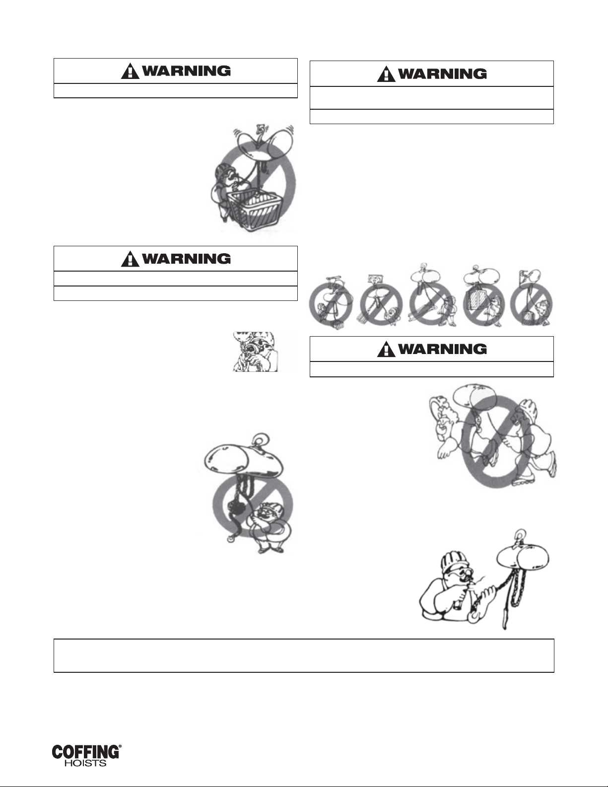
To avoid personal injury:
do not use the equipment shown in this manual to lift, support,
or otherwise transport people, or to suspend unattended loads
over people.
1-2. SAFETY STANDARDS
All persons concerned with the installation. operation, inspection
and maintenance of these hoists are urged to read American Society
of Mechanical Engineers (ASME) B30.16. That Standard contains
valuable guidelines concerning practices designed to minimize
hazards associated with the use of overhead hoisting equipment.
ASME B30.16 also contains detailed procedures for establishing
hoist inspection and maintenance programs and can be of
signicant assistance in maintaining compliance with OSHA
regulations.
1-3. HOIST CONSTRUCTION AND FEATURES
EC-3 Series Hoists incorporate the following features:
a. Heat-treated alloy steel gearing.
b. Overload limiting clutch.
c. Completely independent mechanical and electrical brakes.
d. Adjustable limit switches.
e. Tough, nylon, weatherproof pushbutton stations.
f. Steel strain cable inside pushbutton cord.
g. Transformer isolated, low-voltage pushbutton controls.
h. Quick voltage conversion on dual-voltage unit .
1-4. BASIC HOIST DATA
The basic hoist models covered by this manual are listed in Table 1-1.
Model No. Rated Load (lb.)
Lift Speed at
Rated Load (ft.
per min.)
Motor HP
EC-2032 2000 32 2
EC-4016 4000 16 2
EC-4024 4000 24 3
EC-6010 6000 10 2
EC-6016 6000 16 3
EC-8008 8000 8 2
EC-8012 8000 12 3
EC-10005 10000 5 2
EC-10008 10000 8 3
1-5. APPLICATION INFORMATION
This hoist is intended for general industrial use in the lifting and
transporting of freely suspended material loads within its rated
load. Prior to installation and operation, the user should review his
application for abnormal environmental or handling conditions and
to observe the applicable recommendations as follows:
a. Adverse Environmental Conditions. Do not use the hoist in areas
containing ammable vapors, liquids, gases or any combustible
dusts or bers. Refer to Article 500 of The National Electric Code. Do
not use this hoist in highly corrosive, abrasive or wet environments.
Do not use this hoist in applications involving extended exposure to
ambient temperatures below -40°F or above 130°F.
b. Lifting of Hazardous Loads. This hoist is not recommended
for use in lifting or transporting hazardous loads or materials
which could cause Wide-spread damage if dropped. The lifting
of loads which could explode or create chemical or radioactive
contamination if dropped requires fail-safe redundant
supporting devices which are not incorporated into this hoist.
c. Lifting of Guided Loads. This hoist is not recommended for use
in the lifting of guided loads, including dumbwaiters and non-
riding elevators. Such applications require additional protective
devices which are not incorporated into this hoist. Refer to
your state and local regulations governing the requirements for
elevator and dumbwaiter installations.
1-6. WARRANTY
Every hoist is thoroughly inspected and tested prior to shipment
from the factory. Should any problems develop, return the complete
hoist prepaid to your nearest Cofng authorized Warranty Repair
Station. If inspection reveals that the problem is caused by defective
workmanship or material, repairs will be made without charge and
the hoist will be returned, transportation prepaid.
This warranty does not apply where: ( 1 ) deterioration is caused by
normal wear, abuse, improper or inadequate power supply, eccentric
or side loading, overloading, chemical or abrasive actions, improper
maintenance or excessive heat; (2) problems resulted from repairs.
modications or alterations made by persons other than factory or
Cofng Authorized warranty Repair Station personnel: (3) the hoist has
been abused or damaged as a result of an accident: (4) repair parts or
accessories other than those supplied by Cofng Hoists are used on
the hoist. Equipment and accessories not of the seller’s manufacture are
warranted only to the extent that they are warranted by the manufacturer.
EXCEPT AS STATED HEREIN, COFFING HOISTS MAKES NO OTHER
WARRANTIES, EXPRESS OR IMPLIED, INCLUDING WARRANTIES OF
MERCHANTABILITY AND FITNESS FOR PARTICULAR PURPOSE.
SECTION II
2-1. SAFETY NOTES
a. Inspect the hoist for any evidence of shipping damage or loose parts.
b. The supporting structure and load attaching devices should
have a load rating at least equal to that of the hoist.
c. This hoist is not suitable for use in uncovered outdoor locations
or areas containing explosive dust, vapors or gases.
d. The installation area must provide safe operating conditions
for the operator, including sufcient room for the operator and
other personnel to stand clear of the load at all times.
e. In areas where slack chain hanging from the hoist may create a
hazard, use a chain container (see Figure 2-2).
2-2. HANGING THE HOIST
Hook mounted hoists can be used with a variety of trolleys or
stationary hangers. It is recommended that a hand-geared or
motorized trolley be used when the pulling effort required to move
the hoist exceeds 100 pounds or when the application requires
frequent movement of the hoist.
a. Make sure that the hook latch closes after hanging the hoist.
b. See Figure 2-1 for instructions on adjusting lug-mounted plain trolleys.
c. Refer to Cofng Motorized Trolley Operating and Maintenance
Instructions manual for motorized trolley installation instructions.

7EC3-680-3 February 2017
Order # 5041558-0 & 5041679-0
2-3. POWER SUPPLY CONNECTION
a. Disconnect power before making connections.
b. Voltage supplied to the hoist should be within plus or minus
10% of the voltage specied for the hoist. Hoists are tagged
at the factory with a tag indicating the voltage for which the
hoist is wired. Standard single-speed, three-phase hoists are
convertible from 460 volts to 230 volts. See the Wiring section
(paragraph 7-1) for voltage conversion instructions.
c. National Electrical Code (ASME C2) and local electrical codes
should be consulted and proper disconnects, branch circuit
protectors, and wiring provided.
d. Power cables furnished with the hoist have a green colored
ground wire which must be securely connected to the electrical
system ground.
e. When installing a three-phase hoist, make only temporary
connections at the power line. Push the “’UP” button and observe
the direction of the hook. If it raises, the phasing is correct and
permanent connections may be made at the power line. If the load
block lowers when the “UP” button is pushed, release the button
immediately since the limit switches will not operate to protect
the hoist from overtravel. Reverse the red and black wires at the
power line connection to correct the hook direction.
Do not change connections in the hoist or the pushbutton assembly.
2-4. VENT PLUG
This hoist is shipped with a factory installed pressure relief tting. This
tting needs no adjustments or maintenance before operating the hoist.
2-5. CHAIN LUBRICATION
The hoist chain should be liberally oiled before placing the hoist into
operation. For lubrication instructions, see paragraph 5-6.a.
2-6. TESTING
a. Before placing the hoist into operation, check for proper limit
switch operation. Push the ‘”UP” button and verify that the
hook block stops at least 2 inches from the bottom of the hoist.
Run the hoist down to its lower limit. At least 12 links of chain
should remain on the slack end. If either switch is not correct.
adjust according to the procedure outlined in paragraph 5-2.
NOTE: The upper and lower limit switches are factory set
to provide the maximum allowable hook travel. This travel
adjustment should not be increased. However, the switches
may be adjusted to stop the hook sooner at either end of
its travel.
b. Attach a light load to the hook and check the hoist for proper
operation. The load should stop without noticeable drift when
the pushbutton is released. Increase the load to near rated
load. The hoist should still lift the load without hesitation and
stop with no more than one-inch drift.
2-7. TROLLEY INSTALLATION
Cofng®CT Series trolleys can be mounted on American Standard
I Beams from 6 to 18 inches high (8-inch minimum on 4- or 5-ton
models). Adjustment for different beam dimensions is accomplished
with the proper placement of spacer washers as described below in
paragraph 2-7.a.
a. “I” Beam Adjustment. Adjustment for “I” beam sizes and
tolerances is accomplished by locating the spacer washers as
shown in Figure 2-1. Normal placement of washers is given in
Table 2-2. Refer to Table 2-1 for identication of part names and
numbers.
BEAM MANUFACTURING TOLERANCES ALLOW WIDE
VARIATIONS FROM HANDBOOK FLANGE WIDTHS, AND SLIGHT
CHANGES TO RECOMMENDED WASHER DISTRIBUTION MAY
BE NECESSARY TO SUIT SPECIFIC INSTALLATIONS.
The particular beam on which your hoist is to be installed should
be measured and trolley spacer washers adjusted as required to
achieve a clearance of 3/32” to 1/8”.
b. Periodic Inspection. The trolley should be inspected periodically
for evidence of excess wear or overload. Parts should be
replaced as required.
c. Lubrication. Trolley wheels are equipped with sealed, lifetime
lubricated, precision ball bearings which should not require
lubrication for the normal service of the trolley.

8EC3-680-3 February 2017
Order # 5041558-0 & 5041679-0
TABLE 2-1. PARTS LIST FOR CT TROLLEY
Model No. Part Name Part Numbers
1, 2 & 4 Ton 3 & 5 Ton
1 Load Pin 103K30-2 103K30-2
2Washer (1/8” Thick) H-4211 H-4211
3Washer (.135” Thick) H-4209 H-4209
4Washer (.075” Thick) H-4210 H-4210
5 Nut H-3945 H-3945
6 Side Plate 5K101 5K101
7 Wheel 45J1P 45J1P
8 Axle 102K11 102K11
9 Retaining Ring H5549 H5549
10 Bearing JF504-2 JF504-2
11 Retaining Ring 5K2658-6W 5K2658-6W
12 Nut (Axle) H-3945 H-3946
13 Washer H-4211 H-4212
FIGURE 2-1. COFFING CT TROLLEY
TABLE 2-2- TROLLEY I-BEAM ADJUSTMENT DATA
“I” Beam Size
6" 8" 10" 12' 15" 18"
1, 2 and 3 Ton
Washers Between
Hoist & Trolley
Thick 0 3 1 4 7 6
Thin 1 0 8 5 3 8
Washers Outside
Trolley
Thick 7 4 6 3 0 1
Thin 8 9 1 4 6 1
4 and 5 Ton
Washers Between
Hoist & Trolley
Thick 1 1 3 6 6
Thin 0 4 3 1 4
Washers Outside
Trolley
Thick 6 6 4 1 1
Thin 5 1 2 4 1

9EC3-680-3 February 2017
Order # 5041558-0 & 5041679-0
FIGURE 2-2. CHAIN CONTAINER INSTALLATION
Do not attempt to store more chain in chain container than that
specied in table or serious damage to hoist may result and
hazardous conditions may be created
Ass'y No. DIM. "A"
Max Hoist Lift (Feet)
Single
Chain
Double
Chain Triple Chain
927JG201 16" 15' – –
927JG202 20" 30' 15' 10'
927JG203 24" 50' 25' 16-1/2'
927JG204 35" 75' 37-1/2' 25'
927JG205 48-3/4" 100' 50' 33'
Ass'y No. DIM. "A"
Max Hoist Lift (Feet)
Single
Chain
Double
Chain Triple Chain
927JG207 28" 150' 75' 50'
927JG208 35" 200' 100' 66'

10 EC3-680-3 February 2017
Order # 5041558-0 & 5041679-0
2-8. CHAIN CONTAINER INSTALLATION
a. Operate hoist in “down’’ direction until it is stopped by the limit
switch. Disconnect the slack end of the chain from the hoist
by using a small screwdriver to slide the spring-loaded pin to
the left. At least 12 inches of chain should hang from the hoist.
If less than 12 inches of slack chain is present, readjust lower
limit switch using the procedures detailed in paragraph 5-2.b.
b. Place the chain container in position with the spout toward the
hoist. Place a hex head screw through each mounting chain
with a at washer between the chain and the head of the screw.
Fasten each of the two mounting chains to the tapped holes on
the side of the hoist, being sure the chains are not twisted.
c. Be sure the end of the chain is started into the container. Run
hoist up until the hook block is even with the bottom of the
chain container.
d. Reset upper limit switch at this position (see paragraph 5-2.a) to
prevent the possibility of raising a load into the chain container.
SECTION III OPERATION
3-1. GENERAL
This section presents information concerning the proper operation
of the Cofng® Electric Chain Hoist. It is not intended to serve
as a handbook on rigging. Rigging, the process of moving heavy
loads using mechanical devices, requires special knowledge and
equipment. For information on the safe use of slings and similar
rigging gear, users are urged to consult a textbook on rigging.
3-2. SAFETY NOTES
a. Inspect the hoist for any sign of loose, broken, or
malfunctioning parts (see Section IV). Any malfunctioning hoist
should be tagged as “out of order” and removed from service
until the defect is corrected.
b. Before starting the hoist, the operator should be certain that all
personnel are clear.
c. Do not lift more than the rated load of the hoist
d. Do not lift people or loads over people.
e. Avoid jogging controls or quick reversals of suspended loads.
f. Do not leave a suspended load unattended.
g. The operator should have a clear view of the load anytime it is
moving and should be sure that the load does not contact any
obstructions.
h. Read ASME I B30.16 Safety Standard for Overhead Hoists.
3-3. HANDLING THE LOAD
a. Align hoist directly over load. Avoid side pull.
b. The hoist chain should not be wrapped around the load. Use
proper slings.
c. Be sure there are no twists in the load chain as it enters the hoist.
This condition should be constantly checked on double or triple
chain hoists because it is possible for the load block to be
“capsized” or flipped over one or more times, putting twist in the
chain. The presence of twist may not be obvious when the hook
block is in the lowered position but can cause serious chain
binding when the hook block is in its fully raised position.
d. Bring the hook into engagement with the load and make sure it is
well seated before proceeding to lift the load. On multiple reeved
hoists, be sure that the load is equalized on all supporting chains.
e. Lift the load just clear of its supports and stop the hoist
to check for proper brake operation.
f. Avoid letting the hook or load swing excessively
while moving a trolley suspended hoist.
3-4. OVERLOAD LIMITING PROTECTION
This hoist is equipped with a factory-calibrated overload limiting
clutch, which will permit the lifting of loads within its load rating,
but will prevent the lifting of damaging overloads while the hoist is
being operated. If the load being lifted exceeds the lifting capability
of the overload clutch, the hoist motor will continue to run, causing
overheating of both the clutch and the motor. This condition should
be avoided by immediately releasing the “UP”’ button and reducing
the load to within the hoist load rating.
The overload limiting clutch is an emergency protective
device and should not be used to measure the maximum
load to be lifted. or to sense the overload imposed by a
constrained load. Manufacturing tolerances require that the
clutch be set somewhat above the load rating of the hoist.
The fact that the hoist will pick up loads in excess of its load
rating does not in any way sanction the use of the hoist in an
overloaded condition.
SECTION IV INSPECTION
4-1. GENERAL
A scheduled inspection routine should be established for this hoist based
upon severity of use and environmental conditions. Some inspections
should be made frequently (daily to monthly) and others periodically
(monthly to yearly). It is suggested that an inspection and Maintenance
Check List and an Inspector’s Report similar to those shown in Figures 4-1
and 4-2 be used and led for reference. All inspections should be made
by a designated inspector. Special inspections should be made after any
signicant repairs or any situation causing suspicion that the hoist may
have been damaged. Any hoist which has been removed from service for
an extended time should receive an inspection as described under Periodic
Inspections. ASME B30.16, Safety Standard for Overhead Hoists, provides
guidelines for hoist operation and inspection.
Any unsafe condition disclosed by any inspection must be
corrected before operation of the hoist is resumed.
4-2. FREQUENT INSPECTION
a. Check pushbutton station, brake, and limit switches
for proper operation.
b. Check hooks for deformation, chemical damage, or cracks.
Bent hooks or hooks damaged from chemicals, deformation,
cracks, or having excessive throat opening (see paragraph 4-6)
should be replaced. Visible deformation of any hook may be
evidence of hoist abuse and overloading and indicates that a
thorough inspection of the complete hoist should be made.
c. Check that bottom hook swivels freely.
d. Check for missing, bent or otherwise damaged hook latches.
e. Check pushbutton and power cord for cuts or other damage.
f. Check load chain for adequate lubrication, as well as for signs
of excessive wear or stretch, cracked, damaged or twisted
links, corrosion or foreign substance.

11 EC3-680-3 February 2017
Order # 5041558-0 & 5041679-0
INSPECTION SCHEDULE AND MAINTENANCE REPORT
Type of Hoist Capacity (Tons)
Location Original Installation Date
Manufacturer Manufacturer’s Serial No.
Item
Frequency of Inspection
Possible Deficiencies OK Action RequiredFrequent Periodic
1-12 Months
Daily Monthly
Operating Controls • • • Any deficiency causing improper operation
Limit Switches • • •
•
Any deficiency causing improper operation
Pitting or deterioration
Disc (Motor) Brake • • •
•
Slippage or excessive wear
Glazing, contamination or excessive wear
Load Brake/ Mechanical • Failure to support load with disc brake open (see paragraph
4-3 f)
Hooks • •
•
•
Excessive throat opening, bent or twisted more than 10
degrees, damaged hook latch, wear, chemical damage, worn
hook bearing
Cracks (use dye penetrant, magnetic particle or other suitable
detection method)
Suspension Lug (if used) • •
Crack, excessive wear or other damage which may impair the
strength of the lug cracks (use dye penetrant, magnetic particle
or other suitable detection method)
Chain • • • Inadequate lubrication, excessive wear or stretch, cracked
damaged or twisted links, corrosion or foreign substance
Hook and Suspension
UigConnections •Cracks, bending, stripped threads, loose mounting screws
Pins, Bearings, Bushings, Shafts,
Couplings, Chain Guides •Excessive wear, corrosion, cracks, distortion
Nuts, Bolts, Rivets • Looseness, stripped and damaged threads, corrosion
Sheaves • Distortion, cracks and excessive wear. Buildup of foreign
substances
Housing, Load Block • Distortion, cracks and excessive wear, internal buildup of
foreign substances
Wiring and Terminals •Fraying, defective insulation
Contact Block, Magnetic Hoist
Control Switch, Other Electrical
Apparatus
•
Loose connections, burned or pitted contacts
Supporting Structure and Trolley
(if used) •Damage or wear which restricts ability to support imposed
loads
Nameplates, Decals, Warning Labels •Missing, damaged or illegible
Transmission Lubricant • Low level, requires changing
Note: Refer to Maintenance and Inspection Sections of the Hoist Maintenance Manual for further details.
FREQUENCY OF INSPECTION:
Frequent - Indicates items requiring inspections daily to monthly. Daily inspections may be performed by the operator if properly designated.
Periodic - Indicates items requiring inspection monthly to yearly Inspections to be performed by or under the direction of a properly designated person. The exact period
of inspection will depend on frequency and type of usage. Determination of this period will be based on the user’s experience. It is recommended that the user begin
with a monthly inspection and extend the periods to quarterly, semi-annually or annually based on his monthly experience
FIGURE 4-1. RECOMMENDED INSPECTION AND MAINTENANCE CHECK LIST

12 EC3-680-3 February 2017
Order # 5041558-0 & 5041679-0
INSPECTOR’S REPORT
ITEM REMARKS (LlST DEFICIENCIES AND RECOMMENDED ACTION)
Inspector’s Signature Date Inspected Approved By Date
FIGURE 4-2. RECOMMENDED INSPECTOR’S REPORT
4-3. PERIODIC INSPECTION
The exact period for the following inspections will depend on the
anticipated severity of hoist use. Determination of this period should be
based on the user's experience. It is recommended that the user begin
with a monthly inspection and extend the periods to quarterly, semi-
annually, or annually, based on his monthly inspection experience.
a. Clean hoist of any dirt or foreign material. Inspect bottom block
for accumulation of debris.
b. Perform all frequent inspections listed above.
c. Check for loose bolts, screws and nuts.
d. Check housings, load block. and other parts for wear,
corrosion, cracks or distortion. Check for abnormal openings
between housing sections.
e. Check motor brake for worn discs, oil contamination or
excessive clearance (see paragraph 5-3).
f. Check mechanical load brake function (see Figure 4-3).
g. Inspect the entire length of chain for gouges, nicks.
weld spatter, corrosion, distortion and wear. See CHAIN
INSPECTION, paragraph 4-5.
h. Inspect hooks and suspension pans for cracks, distortion or
extreme wear.
i. Inspect hooks for cracks using magnetic particle, dye penetrant
or other crack detecting methods.
j. Check limit switch set points and reset if necessary (see
paragraph 5-2).
k. Inspect all wiring for defective insulation and check to be sure
all electrical connections are tight. Check motor reversing
contactor or relay for burned contacts.
l. Inspect for oil leaks. Check oil level.
m. Inspect for missing or illegible capacity or warning labels.
n. Inspect the supporting structure for continued ability to support
the hoist rated load.
4-4. LOAD BRAKE FUNCTION CHECK
To check the functioning of the mechanical load brake, proceed as
follows:
a. Attach a light load to the hoist and lift it several inches.
b. DISCONNECT HOIST FROM POWER SUPPLY and remove
short end brake cover (see Figure 8-1, Index No. 1).
c. Referring to Figure 4-3 and Figure 8-8, place screwdrivers No. 1
and No. 2 behind the plate and armature assembly and prepare
to pry against the transmission cover.
NOTE: Do not allow either screwdriver to contact brake
disc (see Figure 8-8. Index No. 7).
d. Carefully pry open motor brake (close solenoid gap) and
observe action of load. If the load descends, the mechanical
load brake is malfunctioning and must be repaired.
FIGURE 4-3. LOAD BRAKE FUNCTION CHECK

13 EC3-680-3 February 2017
Order # 5041558-0 & 5041679-0
4-5. CHAIN INSPECTION
Chain inspection and lubrication are the most important aspects of
hoist maintenance. Removal of the chain from the hoist usually is not
necessary, but the chain should be run through the hoist enough that
every link is made visible for inspection.
a. Check each link for gouges. Nicks, weld spatter, corrosion
and distortion.
b. Inspect each link for wear to the diameter of the link (see Figure
4-4). The nominal link diameter is 0.437 inch. If the diameter
of any link of chain is worn to less than 0.350, the entire chain
must be replaced.
FIGURE 4-4. TYPICAL WEAR ON LINKS
c. 1.) Check the chain for overall wear or stretch by selecting
an unworn, unstretched length of chain (at the slack end, for
example). Let the chain hang vertically with a light load (about 20
lbs.) on the chain to pull it taut. Use a large caliper to measure the
outside length of a convenient number of links (about 12 inches).
Measure the same number of links in a used section of chain and
calculate the percentage increase in length of the worn chain.
2.) If the length of the worn chain is more than 1-1/2% longer than
the unused chain (.015” per inch of chain measured), than the
chain should be replaced. If the chain is worn less than 1-1/2%,
check it at several more places along its length. If any section is
worn more than 1-1/2%, the chain should be replaced.
d. The chain used in this hoist is accurately calibrated to operate
over the load sprocket and is very carefully heat treated for
maximum wear life and strength.
1. Do not weld or join hoist load chain.
2. Do not substitute another manufacturer’s chain in this hoist
3. Damage or wear, beyond the stated limits, to any portion
of the chain requires that the entire length be replaced
4-6. HOOK THROAT OPENING
Use Table 4-1 (below) to check hook throat opening.
TABLE 4-1. MAXIMUM ALLOWABLE HOOK THROAT OPENING
Hoist Load Rating (ton) Top Hook* (in.) Bottom Hook* (in.)
1 & 2 1-15/16 1-17/32
3 & 4 1-15/16 1-15/16
5 N/A 1-15/16
*Figures given are for hook with latch. Add 1/16” if measured without hook latch.
SECTION V MAINTENANCE
AND REPAIR
5-1. GENERAL
This section provides instructions for the most common routine
maintenance and adjustments. Major repairs are not within the
scope of this manual and should be referred to qualied service
facilities.
SAFETY NOTE: Always remove load and disconnect hoist from
power supply before removing end covers or making repairs.
5-2. LIMIT SWITCH ADJUSTMENT
Limit switches are provided to protect the hoist against damage
resulting from overtravel. For easy identication the upper (No. 2,
Figure 5-1) and lower (No. 3, Figure 5-1) limit switch adjusting nuts
are colored brass and zinc respectively. Each limit switch nut has
ten slots for adjustment, and the increment of adjustment is such
that one slot is equivalent to one link of chain travel. Care should be
exercised when adjusting either limit of travel. When a geared type
limit switch is furnished (long lift hoists) each adjustment is equal to
3 links of chain, or 30 links per revolution.

14 EC3-680-3 February 2017
Order # 5041558-0 & 5041679-0
FIGURE 5-1. LIMIT SWITCH ADJUSTMENT
a. Adjusting Upper Limit (Brass Nut).
1. Carefully raise the load block to a point where its top is 3” or
more from the hoist housing.
2. DISCONNECT POWER from the hoist and remove the short
end cover.
3. With a screwdriver. pry the spring guide plate (No. 1 , Figure
5-1) out of the slots in the colored limit switch nuts (Nos. 2
and 3).
4. Tum the slotted brass nut (No. 2) toward its limit switch until
the switch clicks.
5. Release the spring guide plate and be sure it snaps back
into the slots in both nuts. Do not disturb the other slotted
nut if it has been previously set.
6. Replace the short end cover and reconnect power to the hoist.
7. Carefully raise the load block to its upper limit and observe
to see if it stops automatically at the desired point. Do
not allow the load block to run into the hoist housing. The
stopping point should be at least 3” below the hoist housing.
b. Adjusting Lower Limit (Zinc Nut)
1. Carefully lower the load block to a point where at least 12
links of Slack chain hang down from the hoist housing.
2. DISCONNECT POWER from the hoist and remove the short
end cover.
3. Adjust the zinc limit switch nut in the same manner
described above for the red nut.
4. Replace the short end cover and reconnect power to the
hoist.
5. Carefully lower the load block to its lower limit and observe
if it stops automatically at the desired level. Do not run chain
out of hoist or allow the slack end loop to become taut
against the hoist housing. At least 12 links of slack chain
should hang from the hoist.
NOTE: If upper and lower limits are not operating satisfactorily,
repeat adjustment.
5-3. MOTOR BRAKE ADJUSTMENT
When properly adjusted, the multiple disc motor brake should
release promptly, operate without noticeable chatter, and stop the
load with no more than one inch of drift. If the hoist hesitates to lift
the load promptly when the pushbutton is depressed. the brake
should be adjusted per the following procedure.
FIGURE 5-2. MOTOR BRAKE ADJUSTMENT
a. Remove any load and DISCONNECT POWER from hoist.
b. Remove the short end cover.
c. Referring to Figure 5-2, check the gap between armature (A)
and frame (B). The correct gap is .015”.
d. Adjust the gap by turning the three lock nuts (F) and check with
a feeler gauge to be sure the gap is the same on both ends of
the solenoid.
Be sure the bottom of the armature does not touch the
splined adapter (H). As wear occurs, the original clearance
will be reduced when this clearance is gone; THE BRAKE
DISCS MUST BE REPLACED.
e. Replace short end cover and reconnect power. If the brake
still chatters or is hesitant to release, refer to Section VI,
Troubleshooting.
5-4. TOP SUSPENSION REMOVAL
AND REPLACEMENT
A number of different top suspension assemblies are available to
accommodate different methods of hanging the hoist. If it should be
necessary to change top suspensions, proceed as follows:
a. DISCONNECT POWER from hoist and move the hoist to a safe
working area. If necessary, remove trolley to gain access to the
cap screws bolting the top suspension to the frame of the hoist.
b. Remove cap screws and lift off the suspension assembly.
NOTE: Due to the variety of mounting arrangements and
different reeving available on EC-3 Series hoists it is possible for
any suspension assembly to be mounted in several positions.
Refer to the diagrams of Figure 5-3 for proper suspension
location and orientation.
c. Check to be sure proper length cap screws are being used with
any change of top suspension. Screws should have ¾ to 1 inch
thread engagement.
d. Install new suspension assembly and tighten cap screws to
75 ft.-lbs. torque.

15 EC3-680-3 February 2017
Order # 5041558-0 & 5041679-0
5-5. CHAIN REPLACEMENT
(OLD CHAIN STILL IN HOIST)
Refer to Figure 5-5, Chaining Diagrams, and proceed as follows:
a. Run the load block up to its top limit.
b. DISCONNECT PO\VER from the hoist and remove the short
end cover.
c. With a screwdriver, push the spring guide plate (No 1. Figure
5-1) out of the slots in the limit switch nuts. Tum the brass
slotted nut ( 2) back to about the cen ter of the threaded
screw DO NOT DISCONNECT THE WIRES FROM THE LIMIT
SWITCHES.
d. Remove the load hook assembly from the old chain.
e. Make a “C”-shaped chain link by grinding through one side of
the end link of either the old or new chain. See Figure 5-4.
f. Hook the special “C” link to the end link of both chains thus
joining them. BE SURE the welds of the upstanding links of the
new chain are out away from the load sheave. and that proper
orientation is observed for attachment of the slack end in
paragraph j. below.
g. With the end cover off, connect the hoist to power supply. Be
sure the green ground wire is properly grounded.
h. Carefully jog the “UP’” button and run the joined pieces of
chain into the hoist until about 12 inches of the new chain
comes out the other side.
i. DISCONNECT POWER from the hoist.
All standard top suspensions will be marked with a letter. Hoist
center sections have each tapped mounting hole marked by a cast-
in number. In order to obtain proper alignment of the top suspension
with the load block, letters and numbers must be placed adjacent to
each other according to the following table. When specied, spacers
are used between the suspension and the hoist frame. See Section
5-4 for suspension change procedure.
Top
Suspension Hoist Capacity Suspension
Letter
Hoist
Number
Spacer
Length
Swivel or Rigid Hook 1, 2 Ton A 3 None
3 or 4 Ton A 8 None
3-5/8" Square Box
With Plain Trolley or
Parallel Mount
Motorized Trolley
1, 2 Ton B 9 None
3 Ton B 2 None
3-5/8" Square Box
With Cross Mount
Motorized Trolley
1, 2 Ton B 9 11/16"
3 Ton B 2 11/16"
7” Square Box With
Trolley
4 Ton C 3 None
5 Ton D 5 None
8 Wheel Plain Trolley 4 Ton B 2 11/16"
5 Ton D 5 11/16"
8 Wheel Motorized
Trolley
4 Ton B 2 1 3/4"
5 Ton D 5 13/4"
FIGURE 5-3. TOP SUSPENSION ORIENTATION

16 EC3-680-3 February 2017
Order # 5041558-0 & 5041679-0
FIGURE 5-4. CHAINING HOIST
j. Remove both the "C" link and the old chain from the slack
end pin (No. 13, Figure 8-6). This can be accomplished by
depressing the pin against the slack end spring (14) with a
small screwdriver. Depress the slack end pin and install the new
chain observing proper orientation of the slack end of the chain
when secured. .Avoid twists in the chain.
k. Adjust the lower limit switch per paragraph 5-2.b.
l. Attach the bottom hook on single-chained hoists to the loose
end of the chain. On double-chained hoists, feed the loose end
of the chain through the load block (welds of the upstanding
links will be in towards the sheave) and fasten the end of the
chain to the dead end pin (No. 31, Figure 8-6B). On triple chain
hoists, feed the loose end of the chain through the load block
(welds toward sheave), around the idler sheave in the hoist, and
to the center of the load block.
m. Adjust the upper limit switch per paragraph 5-2.a (No. 30,
Figure 8-6C)
n. Lubricate the new chain per paragraph 5-6.a and perform an
operation test of the hoist.
5-6. LUBRICATION
Proper lubrication is necessary for long, trouble-free hoist operation.
Refer to the following and to Table 5-1, Recommended Lubrication
Schedule, for lubrication points, type of lubricant, and frequency of
lubrication.
a. Load Chain. Clean the load chain with a non-acid and non
caustic solvent and coat with SAE 90 gear oil. Wipe excess
oil to prevent dripping. If the hoist is used in an atmosphere
containing abrasive dust, the chain should be cleaned and oiled
more frequently. Never apply grease to the chain.
b. Gearing. The gear case of the hoist is lled at assembly with
1 gal. of a gear oil containing special friction-reducing additives.
The use of gear oils other than that recommended in Table
5-1 can cause brake chatter or can render the load brake
incapable of holding a load. A 1 gal. container of this oil is
available from Coffing (Part No. 14J11).
c. To check the oil level, remove the 1/4" pipe plug from the
side of the hoist. With the hoist hanging level, transmission oil
should be even with the edge of the tapped plug hole.
d. The length of time between necessary oil changes will depend
on the severity of use the hoist receives. In general, the oil
should be changed every 12 months of normal operation, or
every 200 hours of actual hoist on-time. Very heavy use or
operation in high ambient temperatures (over 105°F) will require
that oil be changed more often. An indication of the need for oil
replacement is load brake noise. If an erratic tapping sound is
made when lowering a load, the oil should be changed.
e. Limit Switch Shaft. To prevent rust, the threaded limit switch
shaft should be given a light coat of grease or sprayed with a
general purpose lubricant.
f. Idler Sheave Bearing (double and triple chain models only).
Use a grease gun to put about a teaspoon of grease through
the grease ning in the bottom block shaft. Avoid pumping an
excessive amount of grease into the bottom block. On triple
chain hoists, use a grease gun to lubricate the idler sheave in
the hoist until fresh grease pumps from the ends of the sheave.
g. Hook Bearing. Apply a few drops of SAE 30 oil around the edge
of the bearing.
TABLE 5-1. RECOMMENDED LUBRICATION SCHEDULE MODEL EC ELECTRIC CHAIN HOIST
Component Type of Lubricant
Type of Service and Frequency of Lubrication
Heavy Normal Infrequent
Load Chain SAE 90 Gear Oil Daily Weekly Monthly
Gearing
Coffing No. H-7813 transmission oil ( Kit No.
14J11 contains quantity of oil sufficient for one
oil change)
At periodic inspection (See Figure 4-1, paragraph 5-6-B)
Limit Switch Shaft “WD-40” or general purpose spray lubricant Monthly Yearly Yearly
Load Hook Bearing SAE 30 Gear or Motor Oil Weekly Monthly Yearly
Idler Sheave Bearing
(Bushing)
NLGI #2 multi-purpose lithium base grease
(Coffing No. H-7610) At periodic inspection (See Figure 4-1)
NOTE: All bearings except hook and idler sheave bearings are prelubricated and sealed.
* This lubrication schedule is based on a hoist operating in normal environmental conditions. Hoists operating in adverse atmospheres containing excessive heat, corrosive fumes or vapors,
abrasive dust, etc., should he lubricated more frequently.

17 EC3-680-3 February 2017
Order # 5041558-0 & 5041679-0
FIGURE 5-5. CHAINING DIAGRAMS

18 EC3-680-3 February 2017
Order # 5041558-0 & 5041679-0
5-7. CHAIN STOP INSTALLATION
Refer to Figures 8-6A. 6B and 6C, Chaining Parts, and proceed
as follows:
a. Disconnect slack end of chain from hoist.
b. Count (approx.) 12 links from slack end of chain and capture
the twelfth link with the two stop halves.
c. Install and tighten the two cap screws.
d. If no chain container is used, reattach the slack end of the chain
to the hoist. If a chain container is used, drop the slack end of
the chain into chain container.
e. Readjust "down" limit switch as necessary to give a
minimum clearance of 11/2" between chain stop end and
bottom of hoist.
This is a safety device only and is not intended to be a
substitute for the limit switch in the hoist.
SECTION VI TROUBLESHOOTING
6-1. GENERAL
Use the following table as an aid to troubleshoot your hoist. If you do not have an experienced machinist-electrician to do your repair work,
we recommend that you send your hoist to an approved service center for repairs.
Problem Probable Cause Remedy
Hook Fails to
Stop at End of
Travel.
1. Limit switches not operating. 1. Check adjustment. See paragraph 5-2. Check connections against wiring
diagram. Tighten loose connections or replace.
2. Limit switch nuts not moving on shaft. 2. Check for stripped threads or bent nut guide.
3. Magnetic reversing switch malfunction. 3. Remove electrical cover and check reversing switch.
Hoist Does Not
Respond to
Pushbutton.
1. Power failure in supply lines. 1. Check circuit breakers, switches and connections in power supply lines.
2. Wrong voltage or frequency. 2. Check voltage and frequency of power supply against the rating on the
nameplate of the hoist.
3. Improper connections in hoist or pushbutton station. 3. Check all connections at line connectors and on terminal block.
Check terminal block on dual voltage hoists for proper voltage connections.
4. Motor brake does not release. 4. Check connections to the solenoid coil. Check for open or short circuit. Check
for proper adjustment. See paragraph 5-3.
5. Faulty magnetic hoist control switch. 5. Check coils for open or short circuit. Check all connections in control circuit.
Check for burned contacts. Replace as needed.
Hook Does Not
Stop Promptly.
1. Hoist overloaded. 1. Reduce load to within rated capacity of hoist.
2. Brake not holding. 2. Check motor brake adjustment (see paragraph 5-3) and load brake
(Figure 4-3).
Hook Moves in
Wrong Direction.
1. Three-phase reversal. 1. Reverse any two wires (except the green ground wire) at the power source (see
paragraph 2-3).
2. Improper connections. 2. Check all connections against Wiring Diagram.
Hoist Hesitates
to Lift When
Energized.
1. Hoist overloaded. 1. Reduce load to within rated capacity of hoist.
2. Motor brake requires adjustment. 2. Check motor brake adjustment. See Figure 5-2.
3. Worn overload limiting clutch. 3. Replace clutch.
4. Low voltage. 4. Check voltage at hoist power cord with hoist starting. Voltage should be no less
than 90% of voltage specified on hoist.
Hook Raises But
Will Not Lower.
(Motor not
running)
1. “Down” circuit open. 1. Check circuit for loose connections. Check “Down” limit switch for malfunction.
2. Broken conductor in pushbutton cable. 2. Check each conductor in the cable. If one is broken, replace entire cable.
3. Faulty magnetic hoist control switch. 3. Check coils for open or short circuit. Check all connections in control circuit.
Check for burned contacts. Replace as needed.
Hook Raises But
Will Not Lower
When Motor Is
Operating.
Consult Factory or Authorized Duff-Norton Warranty Repair Station.
Hook Lowers But
Will Not Raise.
1. Hoist overloaded. 1. Reduce load to within rated capacity.
2. Low voltage. 2. Determine cause of low voltage and bring up to at least 10% of the voltage
specified on hoist. Line voltage should be measured while holding or lifting load.
3. “UP” circuit open. 3. Check circuit for loose connections. Check “UP” limit switch for malfunction.
4. Broken conductor in pushbutton cable. 4. Check each conductor in the cable. If one is broken, replace entire cable.
5. Faulty magnetic hoist control switch. 5. Check coils for open or short circuit. Check all connections in control circuit.
Check for burned Contacts. Replace as needed.
6. Worn overload limiting clutch. 6. Replace clutch.

19 EC3-680-3 February 2017
Order # 5041558-0 & 5041679-0
SECTION VI TROUBLESHOOTING
Problem Probable Cause Remedy
Lack of Proper
Lifting Speed.
1. Hoist overloaded. 1. Reduce load to within rated capacity of hoist.
2. Motor brake is dragging. 2. Check for proper brake adjustment or other defects. Sec paragraph 5-3.
3. Low voltage. 3. Bring up voltage to plus or minus 10% of voltage specified on hoist. Line
voltage should be measured while hoist is lifting load.
4. Overload limiting clutch intermittently slipping. 4. Replace clutch,
Load Brake
“Noise.” (Erratic
tapping sounds
or squeals)
1 . Need transmission oil change, or improper lubricant has
been used.
1. Change transmission oil. Sec Table 5-1.
Note: Hoist Warranty is void if unapproved oil is used.
2. Load brake malfunctioning. 2. Check load brake operation. See Figure 4-3.
Motor Brake
Noise or Chatter.
(While starting
hoist)
1. Brake needs adjustment. 1. Adjust as per paragraph 5-3.
2. Low voltage. 2. Check voltage at hoist power cord with hoist starting. Voltage should be no less
than 90% of the voltage specified.
Motor Brake
“Buzz.” (Anytime
hoist is running)
1. Brake needs adjustment. 1. Adjust as per paragraph 5-3.
2. Broken shading coil on brake frame. 2. Replace shading coil or complete brake frame assembly.
SECTION VII WIRING
SAFETY NOTES
Disconnect power from hoist before removing end covers.
7-1.VOLTAGE CONVERSION
Standard single speed units are convertible from 460 to 230 volts.
Conversion to the alternate voltage can be accomplished with the
following procedure.
a. Be sure power is disconnected from hoist. Remove long end
cover.
b. To convert the hoist from 460 to 230 volts, reconnect leads
T4, T5 , T6, T7, T8, T9, H2, H4, SI, and S2 per the 230 volt
connection diagram on Wiring Diagram, Figure 7-1.
Do not move any wires or make any changes to the wiring
except at the gray terminal block.
c. After converting voltage, check for proper phasing of three
phase units and check for proper limit switch operation.
7-2. WIRING DIAGRAMS
The wiring diagrams for standard hoist models are reproduced on
the following pages. In addition, every hoist should have a wiring
diagram located inside the long end cover.

20 EC3-680-3 February 2017
Order # 5041558-0 & 5041679-0
FIGURE 7-1. 230/460V, 3 PHASE, SINGLE SPEED HOIST (WIRING DIAGRAM NO. 983LE2100-000)
XFMR CHART
H1 - COM (BLACK)
H2 - 230V (ORANGE)
H4 - 460V (BLACK/RED)
X1 - COM (BLUE)
X2 - 24V (YELLOW)
X2 - 115V (PINK)
C20
C15
C21
DOWN LIMIT
SWITCH
(SILVER NUT)
C14
L2
C14 C15
T1 T2 T3
C3 C4 C5
135
246
135
246
UP DN
A1
A2
A1
A2
L3
H1
C6L1
HOIST
REVERSING
CONTACTOR
XFMR
X2
H1 H2 H4
X1
SEE
XFMR CHART
PB STATION
C20
X1
C21
UP
DOWN
UP LIMIT
SWITCH
(GOLD NUT)
TO POWER SUPPLY
X2 GND
MOTOR
230/460V
T1 T2 T3 T4 T5 T6 T7 T8 T9
BRAKE SOLENOID
(230V COIL)
S1 S2
TERMINAL BLOCKS
87654
321
T4 T8 T9
H2 H4
C6
C5 C4 C3
T7 T5 T6
S1 S2
87654
321
T8 T9
H4 H2
C6
C5
S1
C4
S2
C3
T7
T4
T6 T5
IMPORTANT!
DUAL VOLTAGE HOIST
THREE-PHASE HOISTS ARE FACTORY WIRED FOR 460V. TO
CONVERT VOLTAGE, RECONNECT LEADS TO THE TERMINAL
BLOCKS EXACTLY AS SHOWN BELOW FOR THE REQUIRED
VOLTAGE BEFORE APPLYING POWER TO THE HOIST.
460V
230V
460V
230V
WIRING DIAGRAM
230V, 460V
1-SPEED HOIST
DWG#: 983LE2100-000
This manual suits for next models
9
Table of contents
Other Coffing Hoists Chain Hoist manuals

Coffing Hoists
Coffing Hoists Concert Series User manual

Coffing Hoists
Coffing Hoists ESC-680-1 Installation and operation manual

Coffing Hoists
Coffing Hoists Concert Series User manual

Coffing Hoists
Coffing Hoists EMW Series User manual

Coffing Hoists
Coffing Hoists LSB-B Series User manual

Coffing Hoists
Coffing Hoists EC Series User manual

Coffing Hoists
Coffing Hoists ELC Series User manual