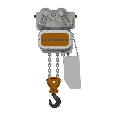
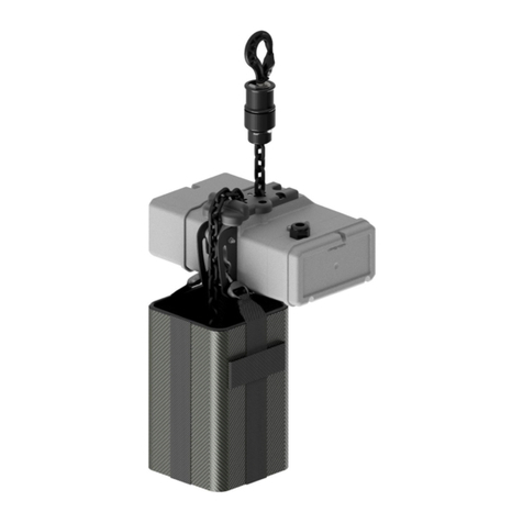
Liftket STAR LIFTKET VFD User manual

OPERATING INSTRUCTIONS - Supplement
STAR LIFTKET VFD | Electric chain hoists
MADE IN GERMANY
www.hoistandwinch.co.uk

2
Please do not use the electric chain hoist before all operators have carefully read and understood this manual and
signed the form on the rear cover.
LIFTKET Hoffmann GmbH
Dresdener Straße 64-68
04808 Wurzen / Germany
+49-3425-89 24-0
+49-3425-89 24-99
sales@liftket.de
www.liftket.de
Ho 07/2021 englisch
Original operating instructions
© 2021
www.hoistandwinch.co.uk

3
Contents
1General information ................................................................................................................................................5
2Technical Overview ................................................................................................................................................5
2.1 Operating Voltage / Control Voltage .......................................................................................................................5
2.2 VFD Layout ............................................................................................................................................................5
3Operating of the VFD Electric Chain Hoists............................................................................................................5
3.1 Selection of the operating mode .............................................................................................................................6
3.2 Reduce Speed Mode ..............................................................................................................................................8
3.3 Hold Speed Mode ...................................................................................................................................................9
3.4 Setting the Frequency Inverter ............................................................................................................................. 10
3.4.1 Keys for Setting .................................................................................................................................................... 10
3.4.2 Adjustable parameters ......................................................................................................................................... 11
3.4.3 Setting new parameters ....................................................................................................................................... 11
3.5 Load spectrum counter ......................................................................................................................................... 11
3.6 Possible fault messages ....................................................................................................................................... 12
www.hoistandwinch.co.uk

4
www.hoistandwinch.co.uk

5
1 General information
The supplement to the operating instruction for electric chain hoists with frequency inverter (VFD series) is only valid in con-
nection with the main operating instruction for electric chain hoists. It only describes the specific operation and possible fault
messages of the electric chain hoists with frequency converter.
The special mentioned points of the supplement to the operating instruction for electric chain hoists with frequency inverter
have priority over the main operating instruction for electric chain hoists.
The electric chain hoists of the VFD series are equipped as standard with:
- A frequency inverter control integrated in the electric chain hoist
- Emergency stop button
- Limit switches for lifting and lowering
- Thermal protection
- Load-dependent control of the lifting speed
- Load spectrum counter in the control.
If there are questions concerning the electric chain hoists with frequency inverter (VFD series), please be prepared to pro-
vide the following data:
- Serial number of the electric chain hoist (see type plate)
- Software version of the frequency inverter (see label at the frequency inverter, under the control cap).
2 Technical Overview
2.1 Operating Voltage / Control Voltage
The electric chain hoists of the VFD series are suitable for operation on either 1-phase or 3-phase mains. The connection
voltage can be found on the type plate or in the inspection book.
The control voltage is 24 VDC.
2.2 VFD Layout
Cap on brake side
Control cap
Display
Motor
Figure 1: VFD Layout
3 Operating of the VFD Electric Chain Hoists
The electric chain hoist is operated via a two-stage control pendant with emergency stop.
Two different operating modes are possible, the Reduce Speed Mode and the Hold Speed Mode. Alternatively, the selec-
tion of a control pendant with analog push-buttons for stepless control of the lifting and lowering movement is possible.
Caution!
The minimum speed at minimum frequency shall only be used for final positioning of the load.
The minimum speed at minimum frequency must not be used to lift or lower the load over the
entire lifting height or long hook paths.
Pressing / pushing the emergency stop button stops any lifting and lowering movement immediately and the brake en-
gages.
The emergency stop button can be unlocked again by turning it to the right. Before unlocking/resetting the cause for actuat-
ing the emergency stop button must be checked and eliminated.
www.hoistandwinch.co.uk

6
3.1 Selection of the operating mode
There are different versions of the PCB on the brake side in the electric chain hoist.
Board 29 HIDA0 AE2FU
Switch position
Operating mode
Dip switch 1
Dip switch 2
Board marking
Reduce speed Mode
Dip switch 1 must be set to 'red.'.
Dip switch 2 must be set to 'digi.'.
Board marking
Hold speed Mode
Dip switch 1 must be on 'hold'.
Dip switch 2 must be set to 'digi.'.
Board marking
Analog button Mode
Dip switch 2 must be set to 'ana.'.
Dip switch 1 is in any position.
Table 1: Operating modes for version with board 29 HIDA0 AE2FU
www.hoistandwinch.co.uk

7
Board 29 HIDA0 AE3FU
Switch position
Operating mode
Dip switch 1
Dip switch 2
Board marking
Reduce speed Mode with Soft Stop
Dip switch 1 must be set to ‚red.'.
Dip switch 2 must be set to ‚digi.'.
Board marking
Reduce speed Mode with Quick Stop
Dip switch 1 must be set on ‚red.'.
Dip switch 2 must be set to ‚ana.'.
Board marking
Hold speed Mode with Soft Stop
Dip switch 1 must be set to ‚hold'.
Dip switch 2 can be set to ‚digi.‘ or ‚ana.‘.
Table 2: Operating modes for version with board 29 HIDA0 AE3FU
www.hoistandwinch.co.uk

8
3.2 Reduce Speed Mode
In Reduce Speed Mode, the maximum achieved lifting speed can be reduced to 5 Hz. As a result, a cautious settling of the
load or a gentle approach to the top hook position is possible.
Lifting in Reduce Speed Mode
Operation of button Lifting
Function
Press on 1st stage
Lifting with minimum frequency according to A062
Pressing down to 2nd stage
Increasing the frequency or lifting speed as long as 2nd stage is pressed
Change back from 2nd stage to 1st stage
Reduce the frequency setpoint and thus the lifting speed
Releasing the button
Immediate stopping of the lifting movement without a ramp due to the brake being en-
gaged
Table 3: Operation of button Lifting in Reduce Speed Mode
Load measuring in Reduce Speed Mode
When passing through the 50 Hz setpoint, a load measurement takes place. The 50 Hz is "frozen" for about 300 ms. The
result of this load measurement determines the maximum frequency or maximum possible lifting speed:
Load
Maximum frequency [Hz]
Full load
50
Without load
100
Partial load
50-100
Table 4: Maximum frequency and alteration rate when lifting in Reduce Speed Mode
Note:
The load measurement at 50 Hz during the lifting process takes place only once if it has not
been stopped in the meantime.
Lowering in Reduce Speed Mode
Operation of button Lowering
Function
Press on 1st stage
Lowering with minimum frequency according to A062
Pressing down to 2nd stage
Increasing the frequency or lowering speed as long as 2nd stage is pressed
Change back from 2nd stage to 1st stage
Reduce the frequency setpoint and thus the lowering speed
Releasing the button
Immediate stopping of the lowering movement without a ramp due to the brake being en-
gaged
Table 5: Operation of button Lowering in Reduce Speed Mode
The maximum lowering speed is regulated via the intermediate circuit voltage. When the limit value of the intermediate cir-
cuit voltage is reached, the frequency is not further increased during lowering. The larger the load, the sooner this point will
be reached.
Load
Maximum frequency [Hz]
Full load
50
Without load
90
Partial load
50 - 90
Table 6: Maximum frequency when lowering in Reduce Speed Mode
www.hoistandwinch.co.uk

9
Note:
Depending on the gearbox, the maximum possible lifting and lowering speeds are electronically
limited at 24 m/min.
Electric chain hoists with a nominal speed of more than 18 m/min at 50 Hz are decelerated be-
fore reaching the 90 Hz or 100 Hz mark.
3.3 Hold Speed Mode
In Hold Speed Mode, any other constant frequencies or speeds can be used in addition to the constant 50 Hz and 100 Hz
frequencies.
Lifting in Hold Speed Mode
Operation of button Lifting
Function
Press on 1st stage
Lifting with minimum frequency according to A062
Pressing down to 2nd stage
Increasing the frequency or lifting speed as long as 2nd stage is pressed
Change back from 2nd stage to 1st stage
The current speed is held
Releasing the button
Immediate stopping of the lifting movement without a ramp due to the brake being engaged
Table 7: Operation of button Lifting in Hold Speed Mode
Load measuring in Hold Speed Mode
When passing through the 50 Hz point, a load measurement takes place. The 50 Hz are "frozen" for about 300 ms. The
result of this load measurement determines the maximum frequency or maximum possible lifting speed:
Load
Maximum frequency [Hz]
Full load
50
Without load
100
Partial load
50-100
Table 8: Maximum frequency and alteration rate when lifting in Hold Speed Mode
Note:
The load measurement at 50 Hz during the lifting process takes place only once if it has not
been stopped in the meantime.
Lowering in Hold Speed Mode
Operation of button Lowering
Function
Press on 1st stage
Lowering with minimum frequency according to A062
Pressing down to 2nd stage
Increasing the frequency or lowering speed as long as 2nd stage is pressed
Change back from 2nd stage to 1st stage
The current speed is held
Releasing the button
Immediate stopping of the lowering movement without a ramp due to the brake being en-
gaged
Table 9: Operation of button Lowering in Hold Speed Mode
The maximum lowering speed is regulated via the intermediate circuit voltage. When the limit value of the intermediate cir-
cuit voltage is reached, the frequency is not further increased during lowering. The larger the load, the sooner this point will
be reached.
www.hoistandwinch.co.uk

10
Load
Maximum frequency [Hz]
Full load
50
Without load
90
Partial load
50 - 90
Table 10: Maximum frequency when lowering in Hold Speed Mode
Note:
Depending on the gearbox, the maximum possible lifting and lowering speeds are electronically
limited at 24 m/min.
Electric chain hoists with a nominal speed of more than 18 m/min at 50 Hz are decelerated be-
fore reaching the 90 Hz or 100 Hz mark.
3.4 Setting the Frequency Inverter
3.4.1 Keys for Setting
The ramps for acceleration and braking during lifting and lowering can be set using various parameters on the control
board.
Display
Unlabeled key rows
(Key assignment)
Figure 2: Arrangement of the keys on the board
Keys
Function
Remarks
Run
not used
ESC
Selection of parameter row / left arrow key
Parameter selection key
Parameter higher
Parameter selection key
Parameter lower
Stop / Reset
STR
Confirm or save selection / Right arrow key
ESC + STR
Open input level
Table 11: Functions of the keys on the board
www.hoistandwinch.co.uk

11
3.4.2 Adjustable parameters
The following parameters can be set:
Parameter
group
Parameter
number
Function
Factory setting
Parameter
values
Remarks
F
002
Acceleration ramp Lifting
5
1 … 10
Values < 3 can lead to error messages
F
003
Deceleration ramp Lifting
1
1 … 10
F
202
Acceleration ramp Lowering
3
1 … 10
Values < 3 can lead to error messages
F
203
Deceleration ramp Lowering
1
1 … 10
A
062
Minimum frequency [Hertz]
10
50 … 200
corresponds to 5 Hz … 20 Hz
A
092
Maximum frequency [Hertz]
9999
5000 … 9999
corresponds to 50 Hz … 100 Hz
Table 12: List of adjustable parameters
3.4.3 Setting new parameters
1. Press the emergency stop button. → The control is de-energized.
Attention: Input terminals of the frequency inverter are not de-energized
2. Remove the control cap (see Figure 1).
3. Briefly press the ESC and STR keys simultaneously → The input level opens.
4. Select the required parameter group (letter) by pressing the ESC key.
5. Use the and keys to select the parameter number.
6. Use the STR key to confirm the selection of the parameter. The current parameter value is shown on the display.
7. To change the parameter value, use the ESC (left) and STR (right) keys to preselect the respective digit of the 4-digit
parameter value.
8. Use the and keys to set the required number of the parameter value Use the STR key to save the selection of
the parameter value.
9. Select parameter d026 (see points 4, 5 and 6) to return to the standard display.
3.5 Load spectrum counter
For convenient documentation of the use of the chain hoist, the control saves operating hours and full load hours, counts
braking cycles and calculates the remaining life time of the chain hoist.
As long as there is no error, the values are continuously shown on the display in recurring order:
No.
Display values
1
Remaining life time [hours]
2
Operating hours [hours]
3
Full load hours [hours]
4
Braking cycles [x100]
5
Inverter temperature [°C]
Table 13: Display values of the load spectrum counter
Note:
The load spectrum counter does not release the operator from keeping records the inspection
book!
www.hoistandwinch.co.uk

12
3.6 Possible fault messages
All messages are shown on the display of the electric chain hoist on the front of the control cap.
A fault can be reset by switching off the mains or by emergency stop. The display of the control unit must have gone out
before the power is switched on again.
Fault
message
Description
Cause
Remedy
E01
over-current event while in constant
speed
motor short circuit
check motor and motor wires
faulty motor wiring
connect motor wires acc. to the wiring di-
agram
immediate load increase
avoid overload
E02
over-current event during deceleration
deceleration ramp too short?
increase parameter values F003 and
F203
motor short circuit
check motor and motor wires
E03
over-current during acceleration
acceleration ramp too short?
increase parameter values F002 and
F202
motor short circuit
check motor and motor wires
overload
reduce load
E04
over-current during other conditions
ground fault
check output wires and motor for ground
fault
E05
overload protection
motor is overloaded
reduce load / duty cycle
E06
braking resistor overload protection
duty cycle of braking resistor exceeded
increase parameter values F003 and
F203
E07
over-voltage protection
brake chopper/brake resistor faulty/over-
loaded
check brake resistor
brake chopper/brake resistor faulty/over-
loaded
increase parameter values F003 and
F203
E08
EEPROM error
excessive ambient temperature
check ambient temperature
noise
eliminate emitter
E09
under-voltage error
low power supply voltage
check power supply
E10
current detection error
inverter to react on EM field
check the surroundings
faulty transformer
replace the VFD control
E11
CPU error
inverter to react on EM field
check the surroundings
faulty inverter
replace the VFD control
E14
ground fault
ground fault between U, V, W and earth
eliminate ground fault (check motor, ca-
bles, wiring)
E15
input over-voltage
intermediate circuit voltage too high
check power supply voltage
E21
inverter thermal trip
inverter overloaded
check motor current
high temperature
check ambient temperature
excessive operation
change operating conditions, increase
paus times
E22
CPU communication error
inverter to react on EM field
check the surroundings
faulty inverter
replace the VFD control
E25
main circuit error
noise, EMC error
eliminate EMC emitter
faulty IGBT
replace the VFD control
E30
drive error
over-current at IGBT
check motor and wires for short cicruit
chain hoist overloaded
reduce load
E38
Low-speed overload protection
overload at <0,2Hz
reduce load
motor blocked or overloaded
check motor
www.hoistandwinch.co.uk

13
Fault
message
Description
Cause
Remedy
E50
brake error
brake does not operate
check brake and braking voltage
check 16-pole flat cable
check brake relay on the PCB
E51
inverter over-temperature
inverter temperature >68°C
reduce duty cycle / switches per hour /
load
high ambient temperature
check ambient temperature
E52
intermediate circuit voltage <342VDC
power off
wait until display turns off. Power on.
ohne
Display does not light up
24V short circuit
check 16-pole flat cable
faulty power supply
check power supply
faulty braking resistor
change braking resistor
Table 14: Fault messages of the VFD control
www.hoistandwinch.co.uk
Table of contents
Other Liftket Chain Hoist manuals
Popular Chain Hoist manuals by other brands

Motorhead
Motorhead 1586250 instruction manual

Haklift
Haklift VANOS250 Original instructions

Tractel
Tractel tralift TT Series Installation, operating and maintenance manual

POWERTEX
POWERTEX PCB-S2 user manual

HADEF
HADEF 27/12 Installation, operating and maintenance instructions

Dawson
Dawson PA200 instructions

Yamato
Yamato H-250 instruction manual

Central Machinery
Central Machinery 44006 Assembly & operating instructions

Forankra
Forankra WRH 800 Original instructions

Hercules
Hercules H-F 1000 Original operating instructions

AMH
AMH X5 Operation & maintenance manual

Columbus McKinnon
Columbus McKinnon Yale handy 250 Translated Operating Instructions