COPYRIGHT ©2021 LIGADO NETWORKS
All rights reserved. This publication and its contents are proprietary to Ligado
Networks. No part of this publication may be reproduced in any form or by any
means without the express written permission of Ligado Networks, 10802 Parkridge
Boulevard, Reston, VA 20191-4334
Ligado Networks, has made every effort to ensure the correctness and completeness
of the material in this document. Ligado Networks shall not be liable for errors
contained herein. The information in this document is subject to change without
notice. Ligado Networks makes no warranty of any kind with regard to this material,
including, but not limited to, the implied warranties of merchantability and fitness for
a particular purpose.
TRADEMARKS
All trademarks, marks, names, or product names referenced in this publication are
the property of their respective owners, and Ligado Networks neither endorses
nor otherwise sponsors any such products or services referred to herein, which are
for informational purposes only. “Ligado Networks,” “MSATe” and the “Ligado
Networks” and “MSATe” logos are the registered trademarks of Ligado Networks.
MCN: 3004073-0002 Rev A
Safety Information
For your safety and protection, read this entire user manual before
you attempt to use the MSATe Radio. In particular, read this safety
section carefully. Keep this safety information where you can refer to it
if necessary.
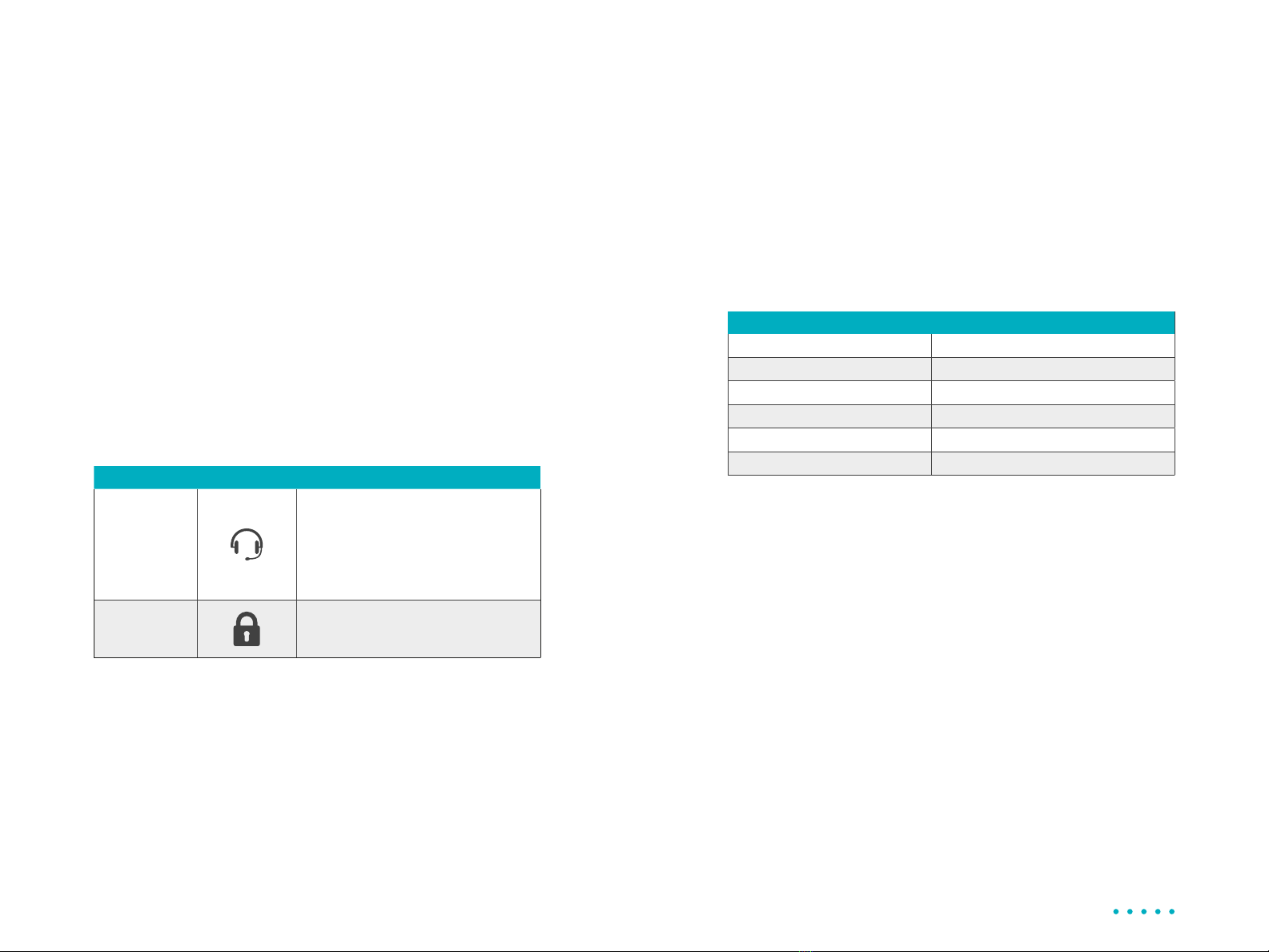
Warning Symbols Used in this Manual
Warning
Potential Radio Frequency (RF) hazard. Where you see this alert
symbol and WARNING heading, strictly follow the warning
instructions to avoid injury to eyes or other personal injury.
Warning
Where you see this alert symbol and WARNING heading,
strictly follow the warning instructions to avoid personal injury.
Danger
Electric shock hazard: Where you see this alert symbol and
DANGER heading, strictly follow the warning instructions to
avoid electric shock, injury or death.
Warnings for MSATe Radio
Safety Information
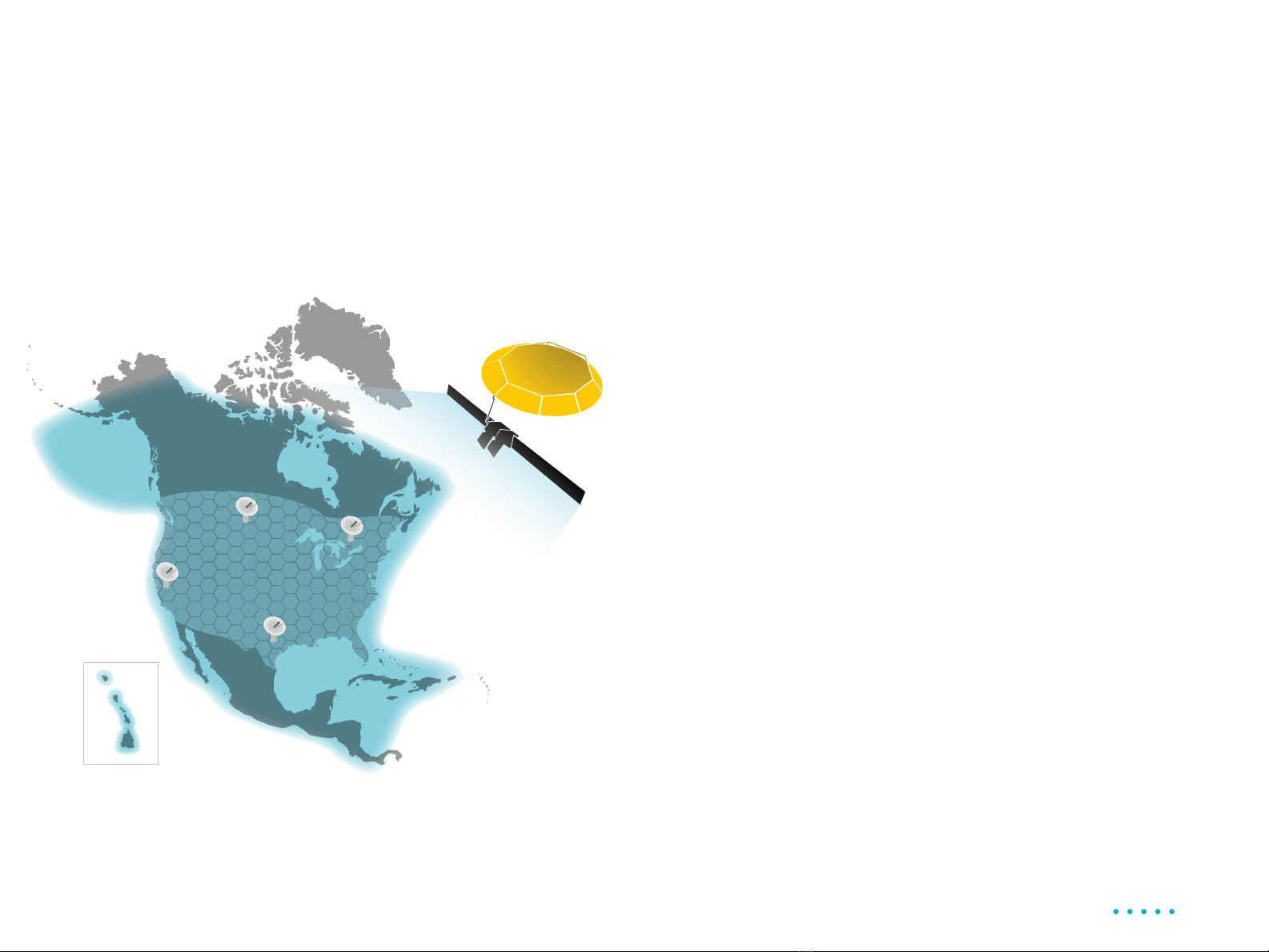
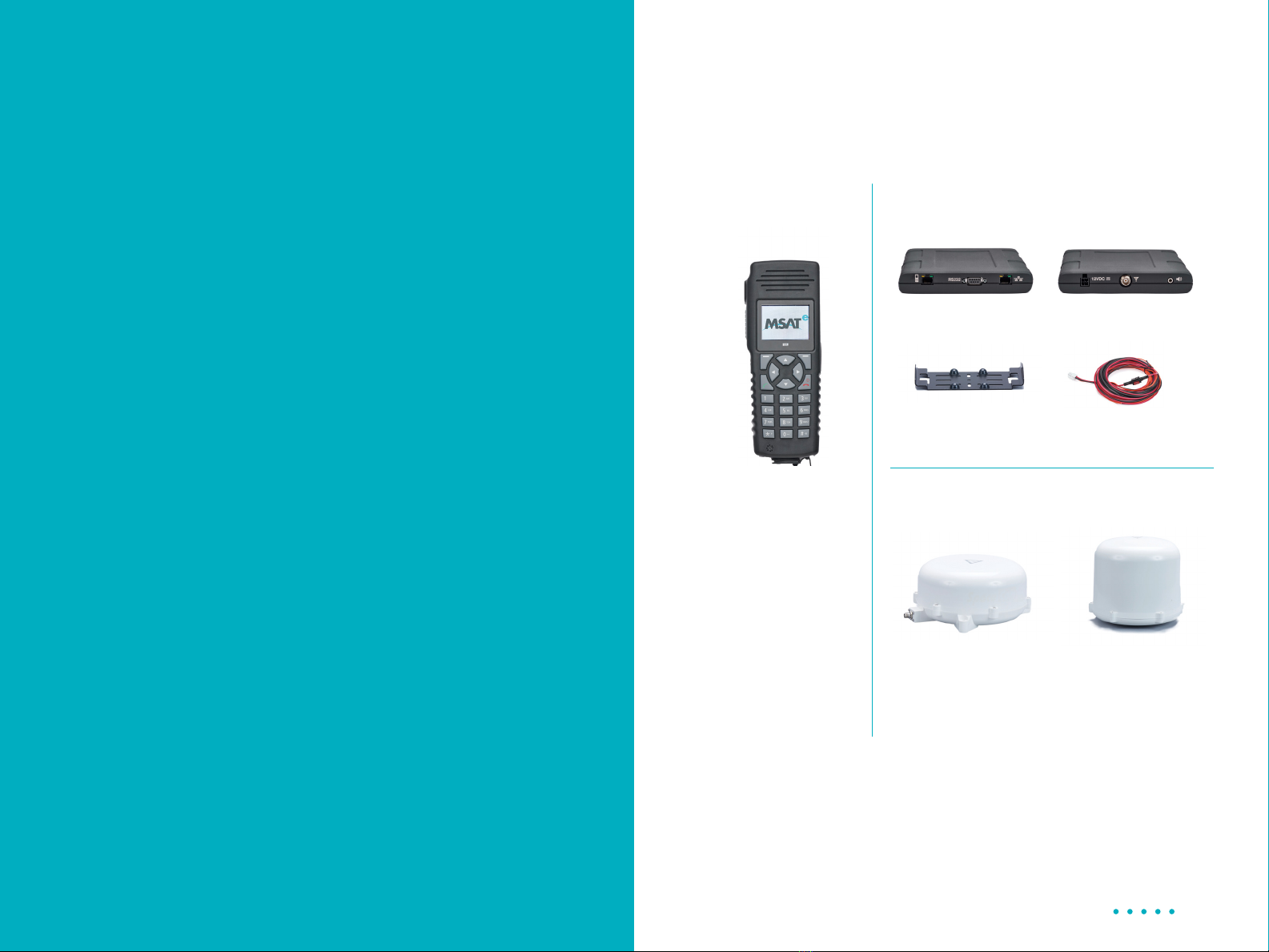
The MSATe Mobile Satellite Radio is a radio transmitter and
receiver. When turned on and operating, the MSATe antenna
transmits and receives radio frequencies to and from a satellite
orbiting the earth.
Installed and used properly the MSATe Radio complies with
the following safety standard: IEC 62368-1:2019, Standard
For Audio/Video, Information and Communication Technology
Equipment. The MSATe radio may be operated safely if no one
is within one (1) meter of the satellite antenna’s transmission
path. The antenna should be installed and operated to ensure
that passersby and passengers of vehicles with vehicle-
mounted antennas will not be closer than the safe distance.
There is a label on the antenna that notifies people of the safe
distance. Please be sure that the label on the antenna remains
visible and attached. If detached, replace immediately.
Use of the MSATe Radio in a manner that is inconsistent with
the safety guidelines stated in this manual may result in physical
harm or other harm to your health.