Light Headed DRC-T2 Series User manual
Subject to change without notice • REV 2021.03.26
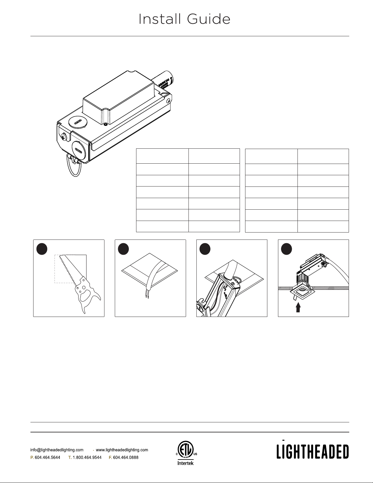
DRC-T2 SERIES
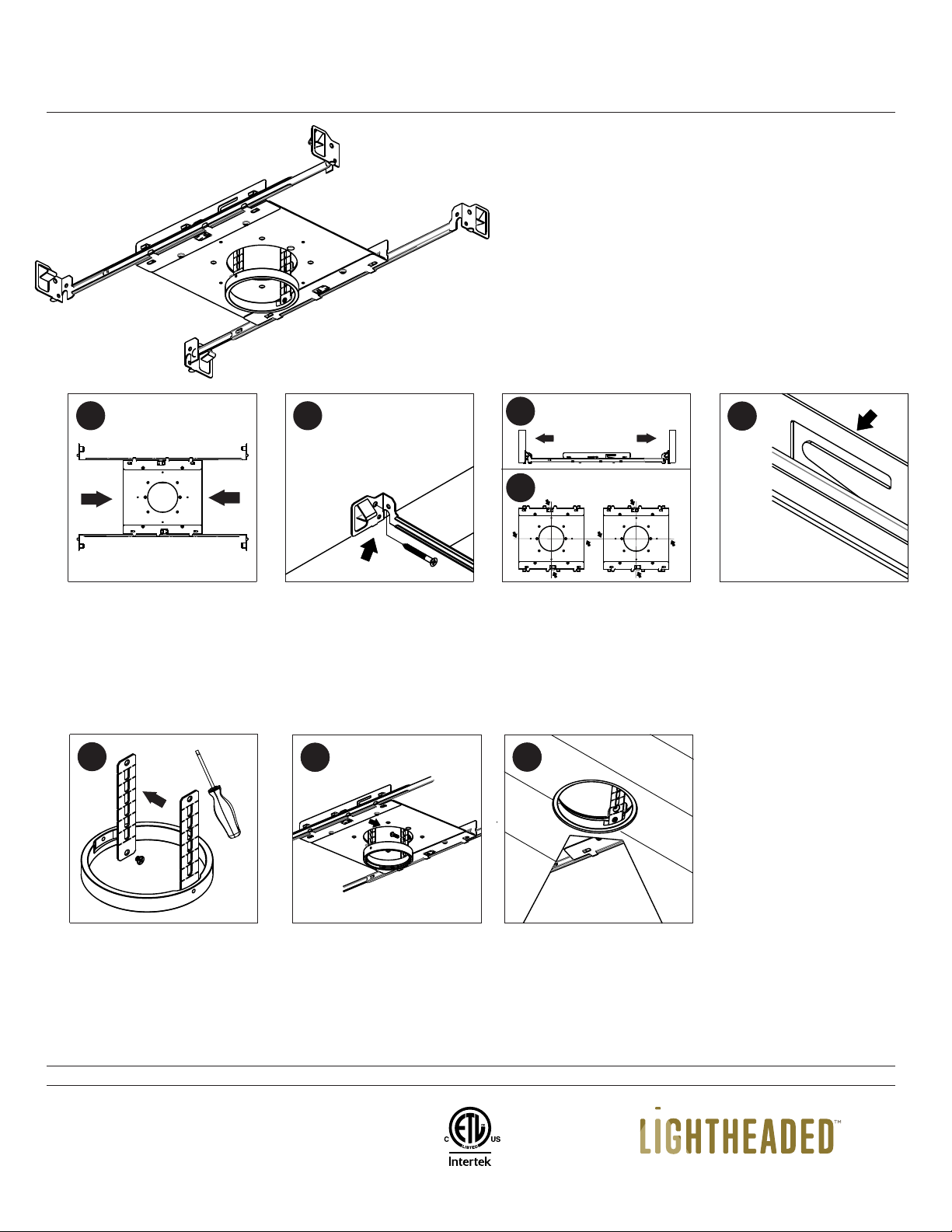
Mark approximate fixture
location in ceiling. See
chart for round or square
hole cutout size for
individual trims
1
Install luminaire into ceiling
4
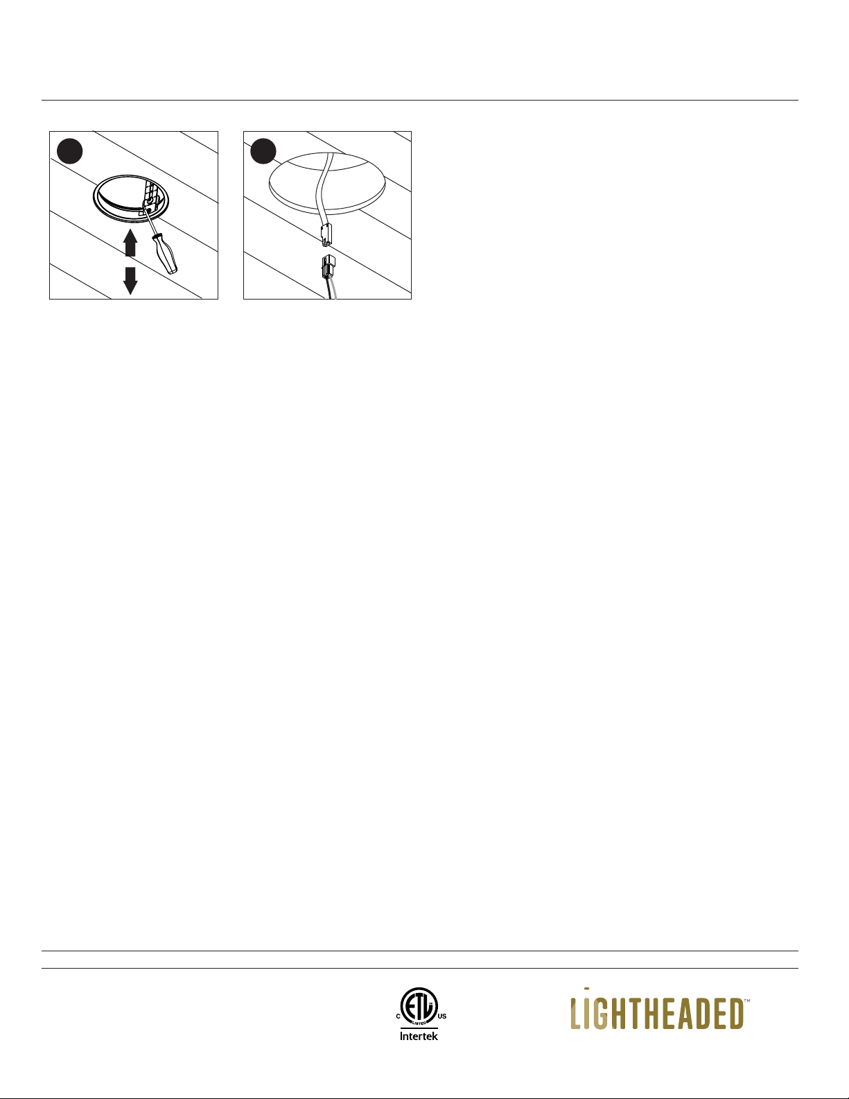
Make appropriate electrical
connection in J-Box. Place
electrical box cover over J-
Box, See Dimming
Instruction Diagram. Push
junction box through the
hole
3
Caution: Careful attention
should be made to cut
within the hole size for
best fit
Pull electrical wire through
newly cutout hole
2
T2SA-TL
HOLE CUTOUT
SIZE
T2RF-TL
T2RA-TL
T2SF-TL
COMPATIBLE
TRIMS
Round 2 7/8"
Square 2 7/8"
Square 2 7/8"
Round 2 7/8"
This product must be installed in accordance with the
applicable code by a person familiar with the
construction and operation of the product and the
hazards involved. Read all of these instructions before
installing.
WARNING: Rated for non-insulated ceilings only (non IC
rated)
T2RP-TL Round 2 7/8"
T2SP-TL Square 2 7/8"
T2SA
HOLE CUTOUT
SIZE
T2RF
T2RA
T2SF
COMPATIBLE
TRIMS
Round 2 5/8"
Square 2 5/8"
Square 2 5/8"
Round 2 5/8"
T2RP Round 2 5/8"
T2SP Square 2 5/8"

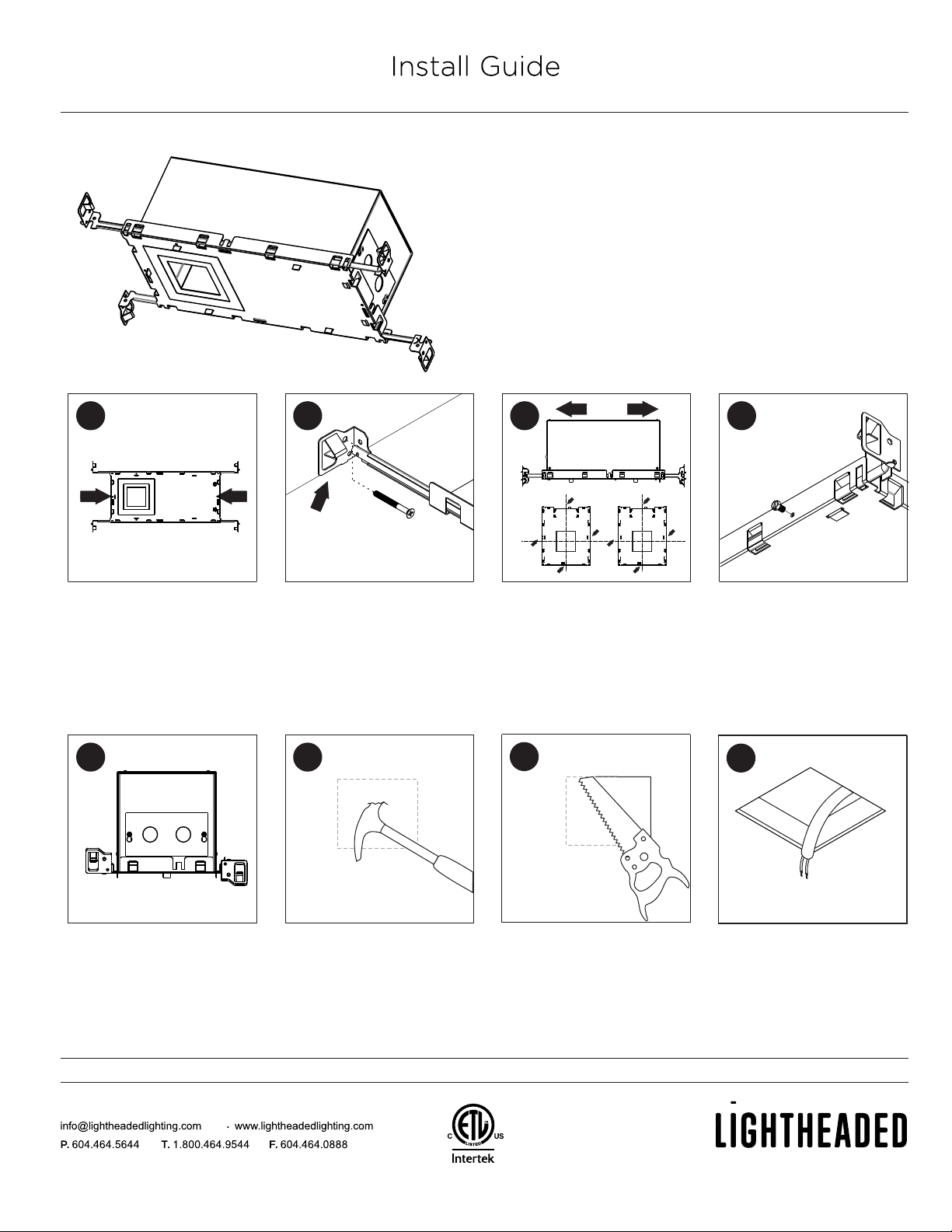
R2P-IC3A/4A
I/C BASEPLATE
Subject to change without notice • REV 2020.11.29
This product must be installed in accordance with the
applicable code by a person familiar with the construction
and operation of the product and the hazards involved. Read
all of these instructions before installing.
WARNING: Rated for insulated ceilings only (IC rated)
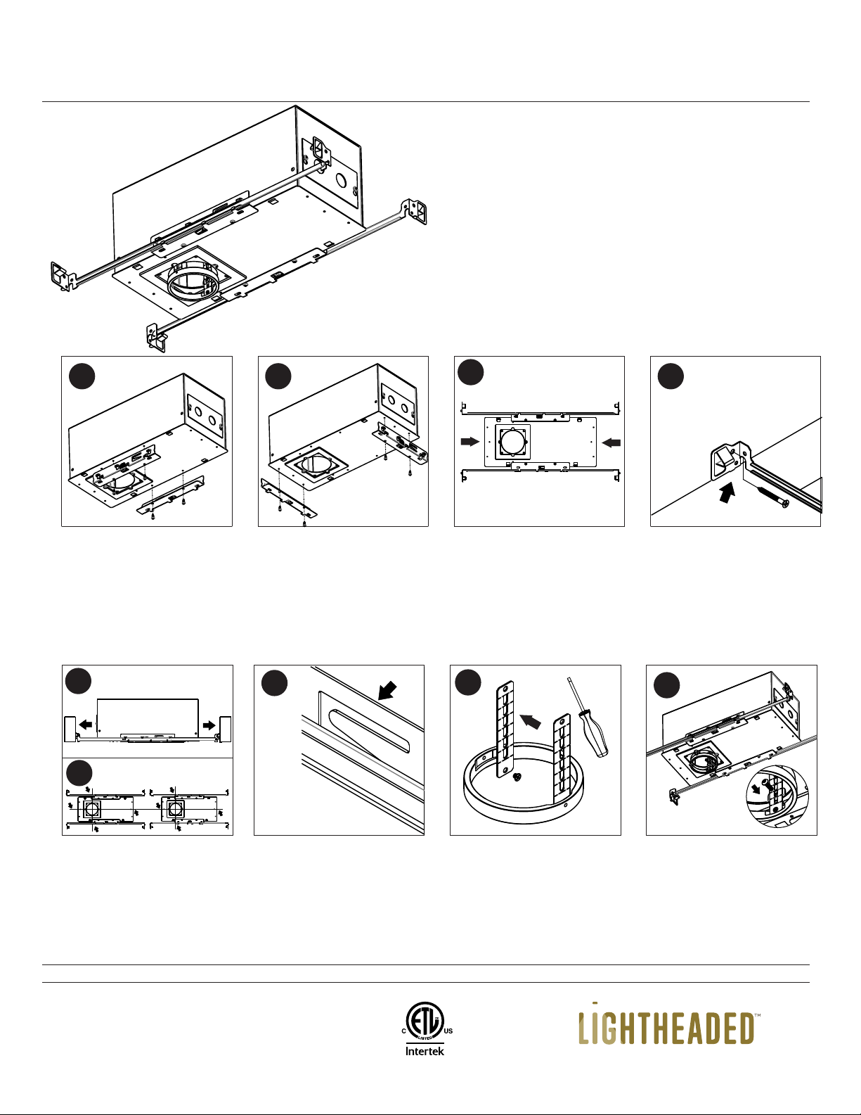
Mark approximate fixture
location in ceiling
Caution: Careful attention
should be made to cut
within the hole diameter
for the best fit
Pull electrical wire through
newly cutout hole
8
To secure housing, install
sheet metal screws as
required to lock hanger bars
in place. Screws by others
4
Slide hanging bars onto
housing base plate
1
Line up bottom edge of
hanging bars with bottom of
wood joist and hammer in
tabs. Nail or screw hanging
bars into place
2
3a — Position trim hole to
desired location by sliding
housing
3b — Use centering holes on
either side of housing base
plate to line up a row of
fixtures
3
Cut open using baseplate
hole as your guide
6
Remove the Knock outs and
make appropriate electrical
connections.
See Dimming Instruction
Diagram.
7
5
R2P-IC3A/4A
I/C BASEPLATE
Subject to change without notice • REV 2020.11.29
This product must be installed in accordance with the
applicable code by a person familiar with the construction
and operation of the product and the hazards involved. Read
all of these instructions before installing.
WARNING: Rated for insulated ceilings only (IC rated)
Mark approximate fixture
location in ceiling
Caution: Careful attention
should be made to cut
within the hole diameter
for the best fit
Pull electrical wire through
newly cutout hole
8
To secure housing, install
sheet metal screws as
required to lock hanger bars
in place. Screws by others
4
Slide hanging bars onto
housing base plate
1
Line up bottom edge of
hanging bars with bottom of
wood joist and hammer in
tabs. Nail or screw hanging
bars into place
2
3a — Position trim hole to
desired location by sliding
housing
3b — Use centering holes on
either side of housing base
plate to line up a row of
fixtures
3
Cut open using baseplate
hole as your guide
6
Remove the Knock outs and
make appropriate electrical
connections.
See Dimming Instruction
Diagram.
7
5
5
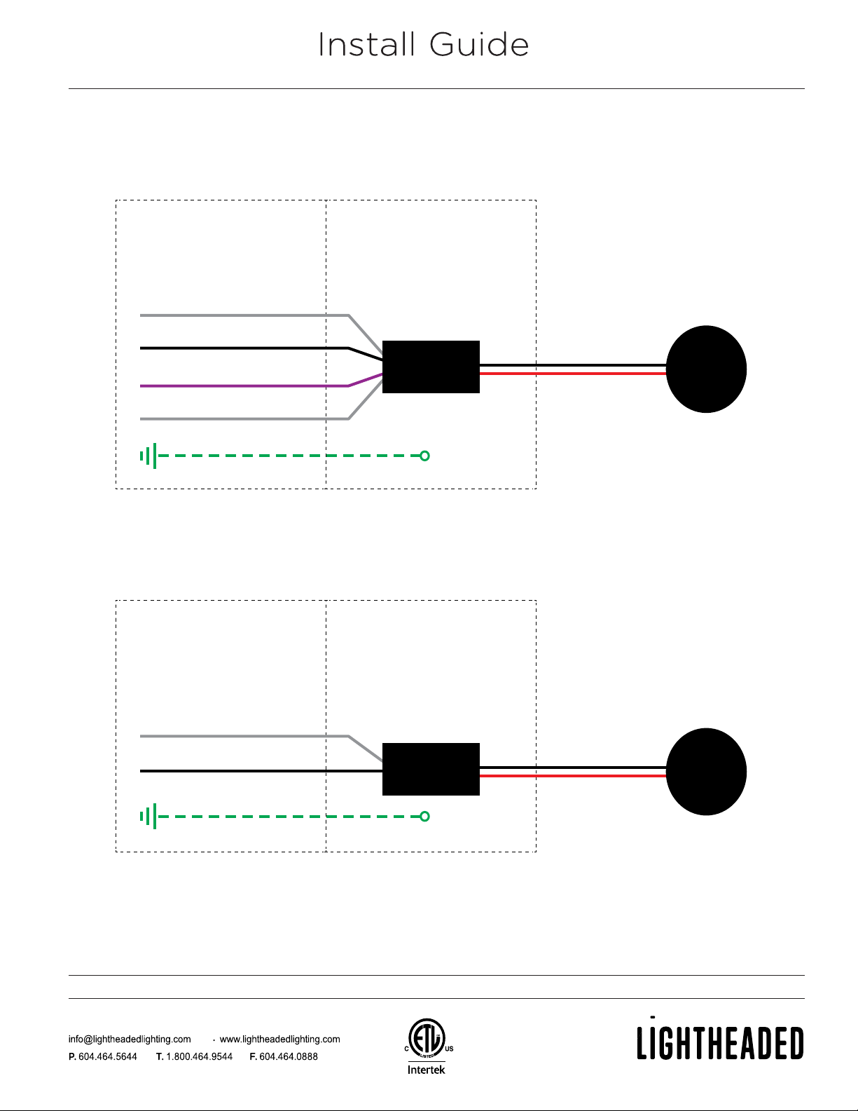
DRC-T2 SERIES
Subject to change without notice • REV 2021.03.26
0–10V (P) DIMMING
PHASE (S) DIMMING
INTERNAL HOUSING WIRING
(Cannot be changed)
JUNCTION BOX WIRING
(Connect to 120VAC or
277VAC, 50/60Hz Input)
Neutral (White)
Hot (Black)
0–10V+ Dimming (Purple)
0–10V- Dimming (Grey)
Ground
LED
Module
Driver
LED- (Black)
LED+ (Red)
INTERNAL HOUSING WIRING
(Cannot be changed)
LED- (Black)
JUNCTION BOX WIRING
(Connect to 120VAC,
50/60Hz Input)
Neutral (White)
Hot (Black)
Ground
LED+ (Red)
LED
Module
Driver
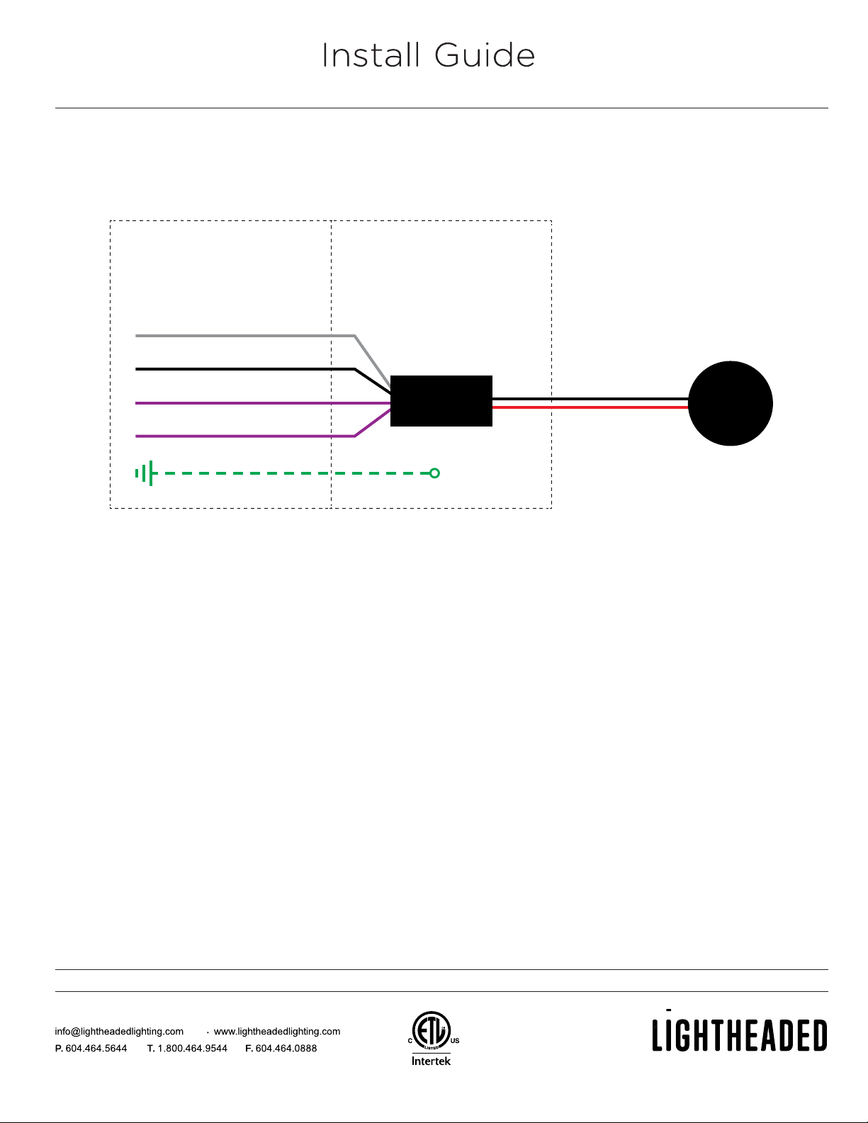
DRC-T2 SERIES
Subject to change without notice • REV 2021.03.26
LUTRON ECOSYSTEM (LH) DIMMING
INTERNAL HOUSING WIRING
(Cannot be changed)
JUNCTION BOX WIRING
(Connect to 120VAC or
277VAC, 50/60Hz Input)
Neutral (White)
Hot (Black)
Lutron EcoSystem E1 (Purple)
Lutron EcoSystem E2 (Purple)
Ground
LED
Module
Driver
LED- (Black)
LED+ (Red)
P. T. F. 604.464.5644 1.800.464.9544 604.464.0888
R2P-F-R-TLW-installation • Subject to change without notice • REV 2021.06.29
Install Guide
R2P-F-R-TLW
NON-I/C BASEPLATE
This product must be installed in accordance with the
applicable code by a person familiar with the construction
and operation of the product and the hazards involved.
Read all of these instructions before installing.
WARNING: Rated for non-insulated ceilings only (non IC rated)
WARNING: Disconnect power prior to servicing or installing.
Line up bottom edge of
hanging bars with bottom of
wood joist and hammer in
tabs. Nail or screw hanging
bars into place
2
5
Slide hanging bars onto
housing base plate
1
3a — Position trim hole to
desired location by sliding
housing
3b — Use centering holes on
either side of base plate to
line up a row of fixtures
3a
Install wood ceiling. Hole
size 3-1/32" to 3-1/16"
Diameter. Can use adapter
ring as template. Do not
use baseplate as hole
template.
7
Place trim ring assembly
inside of baseplate. Utilize
slots on extension arms
which fit best with wood
thickness. Assemble with
provided hex machine
screws to hold in place.
56
3b
Use provided machine
screws to assemble
extension arms to adapter
ring.
5
To lock baseplate in place,
bend tab with pliers over
hanging bar.
54
P. T. F. 604.464.5644 1.800.464.9544 604.464.0888
R2P-F-R-TLW-installation • Subject to change without notice • REV 2021.06.29
Install Guide
Adjust transition ring height
by loosening the 2 hex
machine screws to make
ring recess by 1/16". Trim
will be flush with ceiling
once installed.
8
Connector hangs through
hole until completion. Insert
mating connector from trim
and install trim into ceiling.
9R2P-F-R-TLW
NON-I/C BASEPLATE
This product must be installed in accordance with the
applicable code by a person familiar with the construction
and operation of the product and the hazards involved.
Read all of these instructions before installing.
WARNING: Rated for non-insulated ceilings only (non IC rated)
WARNING: Disconnect power prior to servicing or installing.

P. T. F. 604.464.5644 1.800.464.9544 604.464.0888
R2P-F-S-TLW-installation • Subject to change without notice • REV 2021.06.29
Install Guide
R2P-F-S-TLW
NON-I/C BASEPLATE
This product must be installed in accordance with the
applicable code by a person familiar with the construction
and operation of the product and the hazards involved.
Read all of these instructions before installing.
WARNING: Rated for non-insulated ceilings only (non IC rated)
WARNING: Disconnect power prior to servicing or installing.
Line up bottom edge of
hanging bars with bottom of
wood joist and hammer in
tabs. Nail or screw hanging
bars into place
2
5
Slide hanging bars onto
housing base plate
1
3a — Position trim hole to
desired location by sliding
housing
3b — Use centering holes on
either side of base plate to
line up a row of fixtures
3a
Install wood ceiling. Hole
size 3-1/32" to 3-1/16"
Square. Can use adapter
ring as template. Do not
use baseplate as hole
template.
7
Place adapter ring assembly
inside of baseplate. Utilize
slots on extension arms
which fit best with wood
thickness. Assemble with
provided hex machine
screws to hold in place.
56
3b
Use provided machine
screws to assemble
extension arms to adapter
ring.
5
To lock baseplate in place,
bend tab with pliers over
hanging bar.
54

P. T. F. 604.464.5644 1.800.464.9544 604.464.0888
R2P-F-S-TLW-installation • Subject to change without notice • REV 2021.06.29
Install Guide
Adjust transition ring height
by loosening the 2 hex
machine screws to make
ring recess by 1/16". Trim
will be flush with ceiling
once installed.
8
Connector hangs through
hole until completion. Insert
mating connector from trim
and install trim into ceiling.
9R2P-F-S-TLW
NON-I/C BASEPLATE
This product must be installed in accordance with the
applicable code by a person familiar with the construction
and operation of the product and the hazards involved.
Read all of these instructions before installing.
WARNING: Rated for non-insulated ceilings only (non IC rated)
WARNING: Disconnect power prior to servicing or installing.
P. T. F. 604.464.5644 1.800.464.9544 604.464.0888
R2P-IC3A-R-TLW-installation • Subject to change without notice • REV 2021.06.30
Install Guide
R2P-IC3A-R-TLW
I/C BASEPLATE
This product must be installed in accordance with the
applicable code by a person familiar with the construction
and operation of the product and the hazards involved.
Read all of these instructions before installing.
WARNING: Rated for non-insulated ceilings only (non IC rated)
WARNING: Disconnect power prior to servicing or installing.
Optional Vertical mount.
Align holes and use same
screws.
2
7
Horizontal mount use
provided sheet metal
screws.
1
Line up bottom edge of
hanging bars with bottom of
wood joist and hammer in
tabs. Nail or screw hanging
bars into place
4
Slide hanging bars onto
housing base plate
3
Place adapter ring assembly
inside of baseplate. Utilize
slots on extension arms
which fit best with wood
thickness. Assemble with
provided hex machine
screws to hold in place.
8
Use provided machine
screws to assemble
extension arms to adapter
ring.
6
5a — Position trim hole to
desired location by sliding
housing
5b — Use centering holes on
either side of base plate to
line up a row of fixtures
5a
5b
5b
To lock baseplate in place,
bend tab with pliers over
hanging bar.
Table of contents


