5
5
STEP 1. MOUNT THE LIGHTS
1. Remove the nyloc nut and M10 washer from M10
x 35mm bolt attached to the bottom of mounting
bracket
2. Locate the bracket in a suitable position
using the M10 x 35mm bolt. It is
recommended that the base area of the mounting
bracket is totally supported
3. Align the light to preferred driving position
4. Fit the washer and M10 nyloc nut, then tighten
using a 17mm socket and ratchet to specied
torque (26lb-ft). Do not use rattle guns
5. Tighten 2 x M10 x 35mm side bolts to
recommended torque (35Nm).
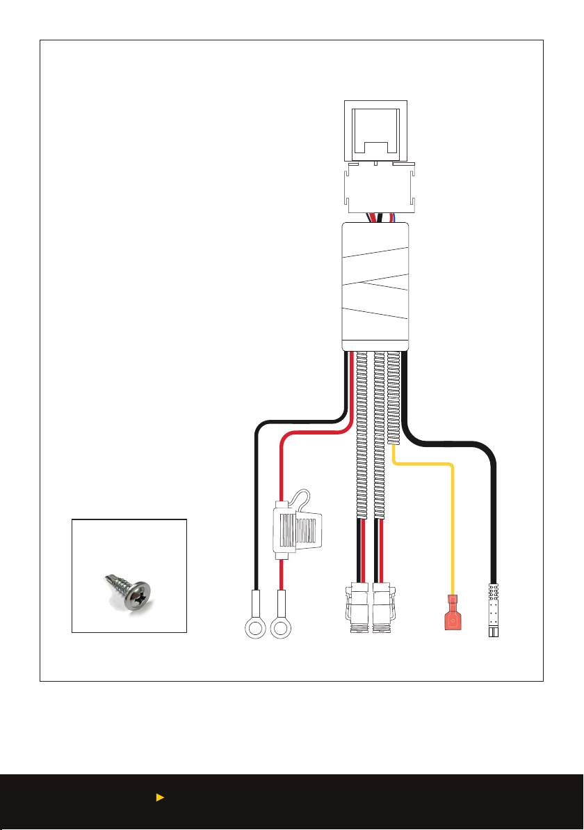
WIRING HARNESS INSTALLATION
STEP 2. INSTALL THE RELAY AND
CONNECT THE LIGHTS
1. Lay out the harness to check length and
positioning
2. Remove the main ground wire from the negative
battery terminal. WARNING: This may result in
loss of radio security code and clock settings.
Please consult your owner’s manual before
disconnecting
3. Mount the 40 amp relay (see gure 1) in a suitable
place within the engine bay, using the screw
supplied (gure 2) and your drill with a Phillips
head driver bit. Ensure that the red (positive)
and black (negative) ring terminals reach the
appropriate battery terminals. DO NOT CONNECT
RING TERMINALS TO THE BATTERY AT THIS
STAGE
4. Route the insulated sleeved wires that run from
the relay to the driving light connectors to each
of your installed Striker LED Driving Lights and
connect the driving light connectors to the back
of each light. Ensure that cables do not touch the
radiator or come in contact with any sharp edges
5. Secure all excess wire to the vehicle with cable
ties supplied.
NOTE: If you are using a different switch
with dash illumination (not included), a
Lightforce Switch Adaptor (not included,
see Figure 9) will be required. Follow the
instructions included with the Lightforce
Switch Adaptor. The yellow dash illumination
cable (item 8 in gure 1) will need to be wired
to the dash light / park light circuit.