F
R
A M E IN
S
TA
L L
ATIO N IN
S
T
R
U
CTIO N
S
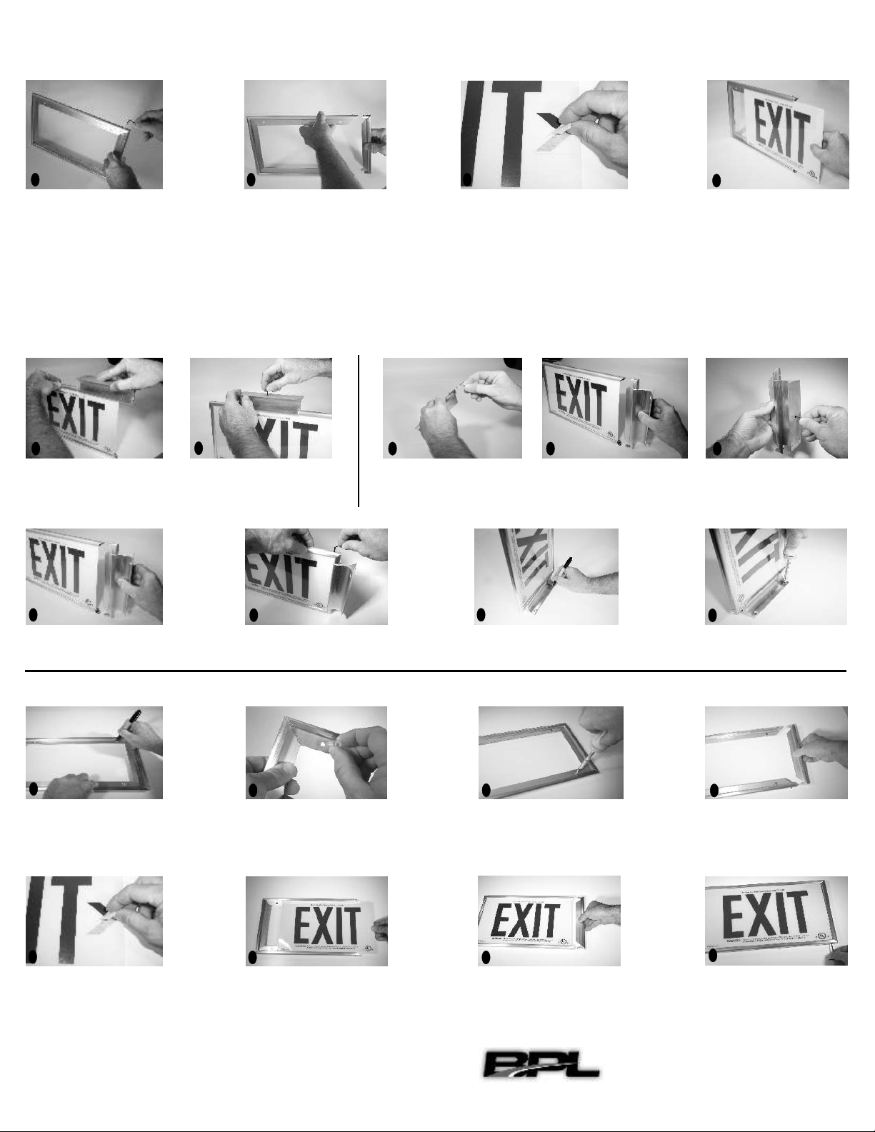
Using the supplied 3/32” Allen
wrench, remove the top and
bottom set screws from one
frame side.
Pull frame side away from frame
assembly.
B
R
I
G
H
T
PA
T
H
L
I
G
H
T
I
N
G
,I
N
C.
Ph.559-443-7300 •Fax.559-443-7393
1-877-343-7300 •bplighting.co
m
F
l
a
g
a
nd
C
eili
n
g
M
o
un
t
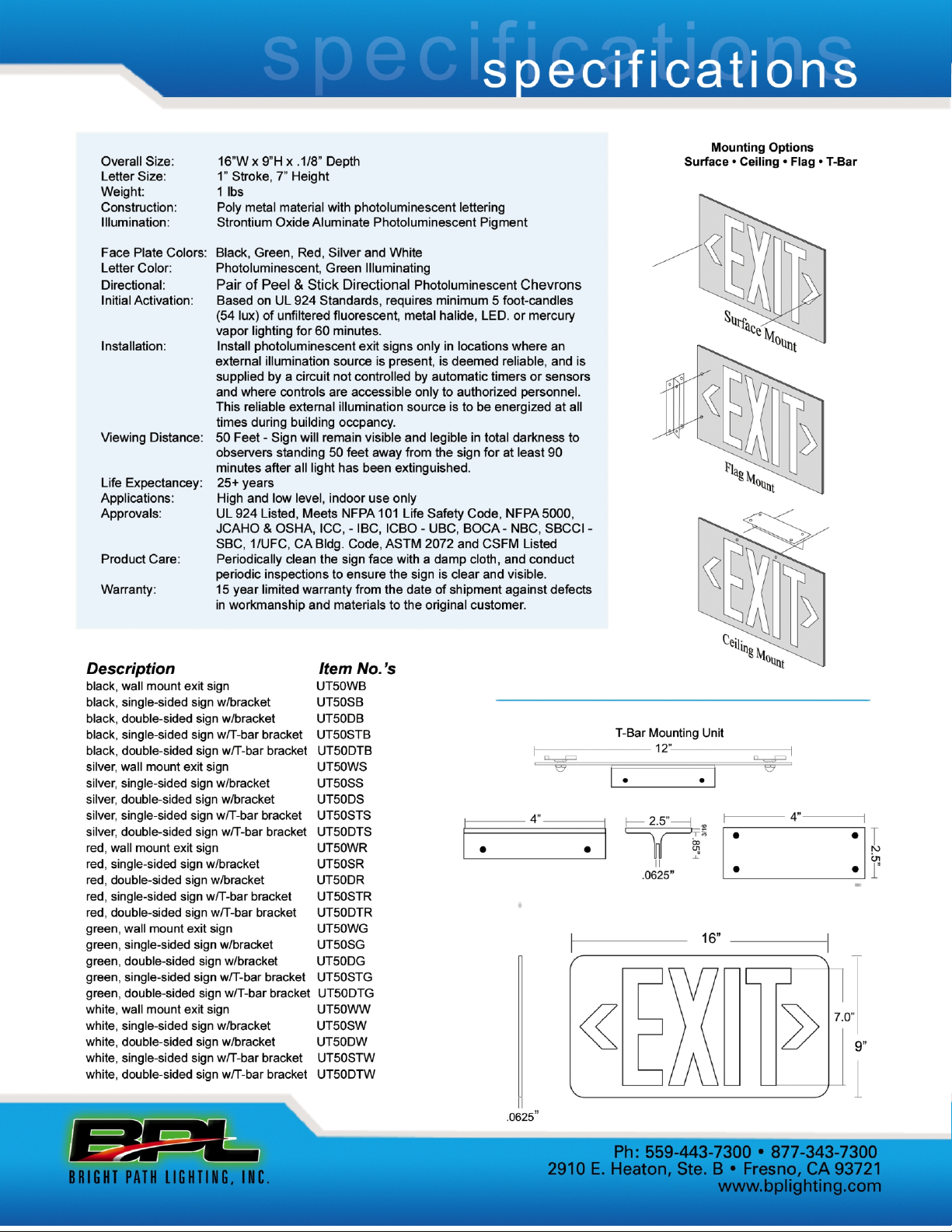
If a directional arrow is to be used, apply
it to the EXIT Sign at this time (arrows are
located on the back side of the EXIT Sign).
For exit paths to the left, apply the arrow
on the left side of the EXIT Sign. For exit
paths to the right, apply the arrow on the
right side of the Exit Sign. For exit paths
straight ahead, no arrows are needed. If
exit paths are located to the left and right,
apply both arrows to the EXIT Sign. Alignment
dots are provided on the face of the sign
to ensure proper positioning of the arrows.
If a directional arrow is to be used, apply
it to the EXIT Sign at this time (arrows are
located on the back side of the EXIT Sign).
For Exit paths to the left, apply the arrow
on the left side of the EXIT Sign. For Exit
paths to the right, apply the arrow on the
right side of the Exit Sign. For Exit paths
straight ahead, no arrows are needed. If
Exit paths are located to the left and right,
apply both arrows to the EXIT Sign. Alignment
dots are provided on the face of the sign
to ensure proper positioning of the arrows
Slide the EXIT Sign into the first
groove of the frame assembly. If
this is a double-sided installation,
prepare a sign and assemble as
pe r st ep s 2 an d 3. S li d e t h e
assembly into the second groove
facing the opposite direction.
•For ceiling mount installation go
to steps A-B.
•For flag mount installation go to
steps C-E.
Ceiling Mount (continued)
S
u
r
f
a
ce
M
o
un
t
Slide the frame base onto the top
frame piece.
Center the base and secure it into
place by tightening the set screw
which is accessible through the
center hole in the bottom of the base.
•Go to steps 6-9.
Flag Mount (continued)
Remove the set screw from one
of the corner angle brackets on the
previously removed frame side.
Remove the corner bracket.
Slide the frame base onto the frame
side. Center the base and secure it
into place by tightening the set screw
which is accessible through the
center hole in the bottom of the base.
Reinstall the corner bracket and
secure using the set screw.
•Go to steps 6-9.
Reinstall the frame side onto the
assembly, being careful to align
the sign into the frame side groove.
Square up the frame. Reinstall and
tighten the previously removed
top and bottom set screws.
Mark the position of the mounting
screws on the wall or ceiling.
Mount the EXIT Sign using proper
hardware and techniques.
With EXIT Sign and Lens removed,
place assembled frame in position
and mark screw hole locations.
If wall anchors will be required,
install them at this time (supplied).
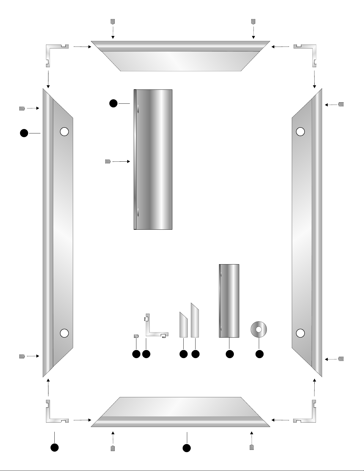
Locate the four supplied frame
spacers. The spacers attach to the
back side of the frame, which is
not countersunk. Attach one self-
adhesive spacer over each frame-
mounting hole.
With the four spacers in place,
position the frame with the spacers
facing the wall. Attach the frame to
the wall by using the four supplied
#8 flat head screws. Be careful not
to over tighten the screws.
Using the supplied 3/32” Allen
wrench, remove the top and bottom
set screws from one frame side.
Pull the frame side away from the
frame assembly
1
6
D
2
7
2
E
3
3
4
9
567
ABC
1
8
Slide the
EXIT Sign into the front
groove of the frame assembly.
Reinstall the frame side onto the
frame assembly being careful to
align the si g n in to t he f ra m e
side groove.
4
8
Reinstall and tighten the previously
removed top and bottom set screws.