LightViper EF-2 User manual

USERMANUALFOR
EF‐2PhysicalLayerEthernet
FiberOpticConverter


1
WarningforYourProtection
1.Readtheseinstructions
2.Keeptheseinstructions
3.Heedallwarnings
4.Followallinstructions
5.Donotusethisapparatusnearwater.
6.Cleanonlywithadrycloth.
7.Donotblockanyoftheventilationopenings.Installinaccordancewiththemanufacturer’sinstructions.
8.Donotinstallnearanyheatsourcessuchasradiators,heatregisters,stoves,orotherapparatus(includingamplifiers)thatproduceheat.
9.Donotdefeatthesafetypurposeofthepolarizedorgrounding‐typeplug.Apolarizedplughastwobladeswithonewiderthantheother.
Agroundingtypeplughastwobladesandathirdgroundingprong.Thewidebladeorthethirdprongareprovidedforyoursafety.Ifthe
providedplugdoesnotfitintoyouroutlet,consultanelectricianforreplacementoftheobsoleteoutlet.
10.Protectthepowercordfrombeingwalkedonorpinched,particularlyatplugs,conveniencereceptacles,andthepointwheretheyexit
fromtheapparatus.
11.Onlyuseattachments/accessoriesspecifiedbythemanufacturer.
12.Useonlywiththecart,stand,tripod,bracket,ortablespecifiedbythemanufacturer,orsoldwiththeapparatus.
Whenacartisused,usecautionwhenmovingthecart/apparatuscombinationtoavoidinjuryfromtip‐over.
13.Unplugthisapparatusduringlightningstormsorwhenunusedforlongperiodsoftime.
14.Referallservicingtoqualifiedservicepersonnel.Servicingisrequiredwhentheapparatushasbeendamaged
inanyway,suchaspower‐supplycordorplugisdamaged,liquidhasbeenspilledorobjectshavefallenintothe
apparatus,theapparatushasbeenexposedtorainormoisture,doesnotoperatenormally,orhasbeendropped.
Theapparatusshallnotbeexposedtodrippingorsplashing.Noobjectsfilledwithliquids,suchasvases,shallbeplacedontheapparatus.
“WARNINGToreducetheriskoffireorelectricshock,donotexposethisapparatustorainormoisture.”

Registration
BesuretoregisteryourLightViperproduct,eitherbyfillingintheenclosedRegistrationCardorbycompletingtheon‐lineregistrationform
atourWebsite:
http://lightviper.com/register
Ifyoudoso,FiberPlexcancontactyouwithanyupdateinformation.Asenhancementsandupgradesaredeveloped,youwillbecontactedat
theregistrationaddress.Pleasereadthismanual‐ifyoucallfortechnicalsupport,we’llassumethatyouhave.
PleaseaddressanyinquiriestoyourdealerordirectlytoFiberPlexat:
FiberPlexInc.
10840‐412GuilfordRd.
AnnapolisJunction,MD20701
301.604.0100Fax:301.604.0773
Warranty,ServiceandTermsandConditionsofSale
ForinformationaboutWarrantyorServiceinformation,pleaseseeourpublished‘TermsandConditionsofSale’.Thisdocumentisavailable
onfiberplex.comorcanbeobtainedbyrequestingitfrom[email protected]orcalling301.604.0100.

3
Disposal
DisposalofPackingMaterials
Thepackingmaterialshavebeenselectedwithenvironmentalanddisposalissuesinmind.Allpackingmaterialcanberecycled.Recycling
packingsavesrawmaterialsandreducesthevolumeofwaste.Ifyouneedtodisposeofthetransportpackingmaterials,pleasetrytouse
recyclablemeans.
DisposalofUsedEquipment
Usedequipmentcontainsvaluablerawmaterialsaswellasmaterialsthatmustbedisposedofprofessionally.Pleasereturnyourused
equipmentviaanauthorizedspecialistdealerorviathepublicwastedisposalsystem,ensuringanymaterialthatcanberecycledis.Please
takecarethatyourusedequipmentcannotbeabused.Afterhavingdisconnectedyourusedequipmentfromthemainssupply,makesure
thatthemainsconnectorandthemainscablearemadeuseless.
DeclarationsofConformity
ClassAEquipment‐FCCNotice
ThisequipmenthasbeentestedandfoundtocomplywiththelimitsforaClassAdigitaldevice,pursuanttoPart15oftheFCCRules.These
limitsaredesignedtoprovideareasonableprotectionagainstharmfulinterferencewhentheequipmentisoperatedinacommercial
environment.Thisequipmentgenerates,uses,andcanradiateradiofrequencyenergyand,ifnotinstalledandusedinaccordancewiththe
instructionmanual,maycauseharmfulinterferencetoradiocommunications.Operationofthisequipmentinaresidentialareaislikelyto
causeharmfulinterference,inwhichcasetheuserwillberequiredtocorrecttheinterferenceattheirownexpense.
Disclaimer
Theinformationinthisdocumenthasbeencarefullycheckedandisbelievedtobeaccurateatthetimeofpublication.However,no
responsibilityistakenbyusforinaccuracies,errors,oromissions,norisanyliabilityassumedforanylossordamageresultingeitherdirectly
orindirectlyfromuseoftheinformationcontainedwithinit.

Introduction
CongratulationsonyourpurchaseofaLightVipersystem.LightViperproductsaredesigned,engineeredandmanufacturedbyFiberPlexInc.,
expertsinfiberopticswithdecadesofexperience.OurworkinaudioanddatacommunicationsproductsisknowninUSgovernment
applicationsworldwide.LightViperproductscombineourfiberoptictechnologywiththehigheststandardsinaudioengineering.
TheEF‐2
YouhavepurchasedtheLightViperEF‐2system,2channelPhysicalEthernetFiberOpticTransportSystem(FTS)thathasabilitytopass
standard10Base‐Tand100Base‐TEthernetcommunicationsaswellasmanyproprietaryPhysicalEthernetbaseddatasuchasthosemade
byAVIOM™.
TheFiberAdvantage
Fiberopticsoffermanyadvantagesovercopper:
Transmitslightratherthanelectrons
Transmissionovergreaterdistances(morethan2Km[1.25mile])
Completeelectricalisolation
ImmunitytoRFIandEMI
Eliminatesgroundloopproblems
Canberoutedoverhead,throughwalls,orunderground
Avoidsfoottrafficwhilemaintainingaesthetics
FunctionalConsiderations
TheLightViperEF‐2isaverysimpledevice.Itisdesignedtobecompletelytransparenttothedata.AsingleEF‐2actuallycontains2
completelyisolatedandindependentchannelsofPhysicalEthernet.Eachchannelsconfigurationiscompletelyseparatefromtheother.To
becompletelytransparenttothedatarequiressomeinitialswitchsettingstoachievethedesiredresult.Thesesettingsaredescribedinthe
laterpartofthisdocument.
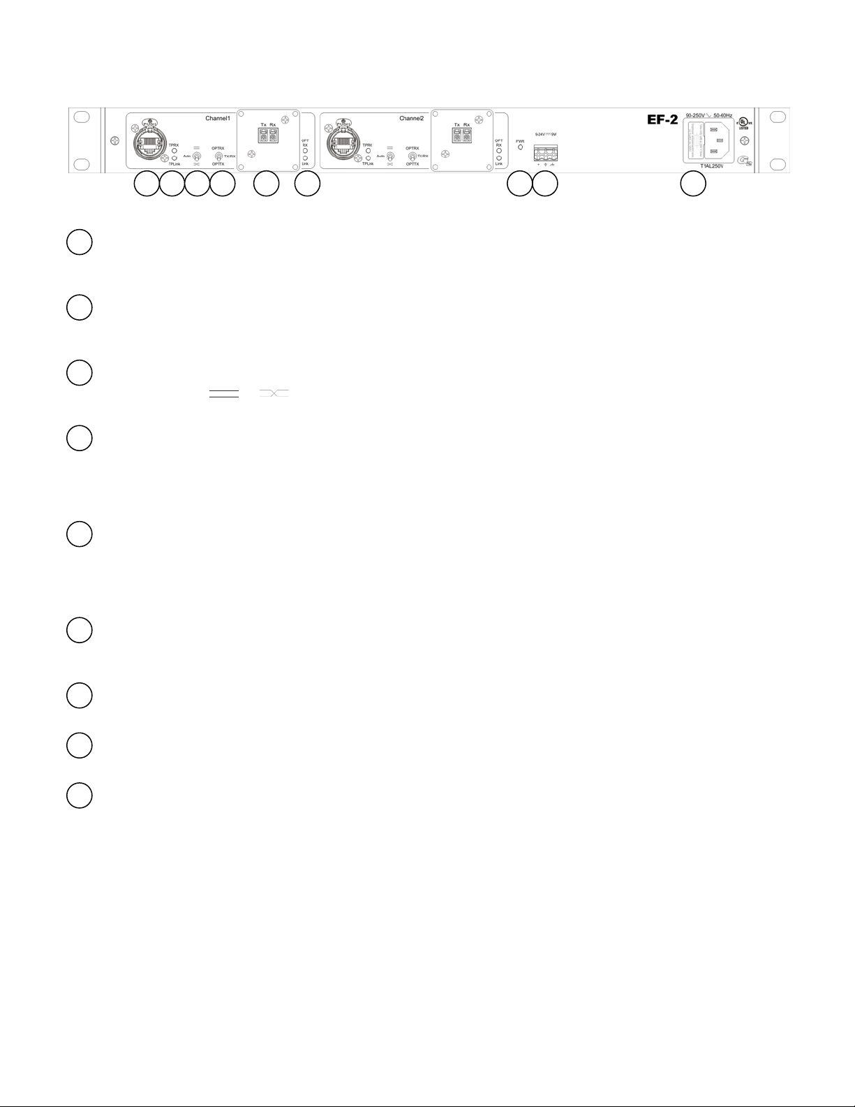
StandardComponents
Initsstandardconfiguration,theLightViperEF‐2ismadeupofthreeprimarycomponents.
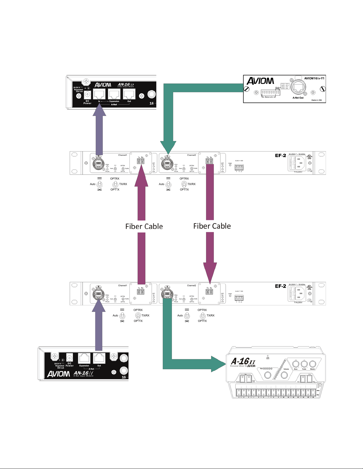
2ea.EthernetTransportdevice(EF‐2)—Thisisthehardwareinterface.Oneunitisplacedoneachendofthefiberconnection.EachEF‐2
canhandletwoindependentPhysicalEthernetchannelsonupto4fibers.
TheFiberCable(TFC‐0000‐04)—Thelightweight“tacticalgrade”fiber‘cable’thatcarriesthedigitalsignalbetweenthestageandmixer
boxes.EitherPVCorPlenumratedfiberisrecommended(VFC‐0000‐D,VFC‐0000‐DP)forinstallationuse.
AdditionallyanEF‐2configurationcanusethefollowingcomponent:
TAC‐4ConnectorPanels(VPL‐11,VPL‐12,VPL‐13)–These1Urackpanelscontain(1),(2),or(3)panelmount
TAC‐4connectorsmountedrespectivelyandallowconnectionbetweentacticalgradefibertotheST
connectorsontheEF‐2units.

5
GettingStarted
Setup
Settingup,andusingyourLightViperEF‐2isaquickandsimpleprocess.Justfollowthesesteps:
1. MountoneEF‐2inarackclosetotheEthernetsource.
2. MounttheotherEF‐2inarackclosetotheEthernetdestination.
3. ConnecttheunitstoeitherACpowerusingtheIECconnectoror12VDCusingthegreenmodularconnector.
4. ConnectandruntheFiberbetweenthetwounits,powerupandcheckthe‘link’lightonbothunits
5. Settheswitchesfortheappropriatesignal.
6. ConnectthedataconnectionstotheRJ‐45jacks.
ThespecificfunctionsoftheLightViperEF‐2(direction,polarity,etc.)areaddressedwithinthismanual.

IndicatorsandControls
Dataconnection
ThedataconnectiontotheEF‐2ismadeviaaNeutrik™EtherconRJ‐45connector.ItusesastandardEthernetpinoutwhichis
configuredusingthePolaritySwitch.Seeappendixforadetailedpinout.
DataStatusLEDs
AYellowindicationontheupperLEDmarked“TPRX”indicatesthatreceivedataisbeingdetectedonthetwistedpair.ThelowerLED
indicatestheLinkstatusonthetwistedpair.Seeappendixformoredetail.
PolaritySwitch
SettingthisswitchtoorsetsthepinoutofTXandRXtoaccommodateconnectiontovariousdevices.Withasettingof
“Auto”,theEF‐2willdeterminethecorrectpinoutsfortheTXandRX.Seetheappendixformoredetail.
DirectionalModeSwitch
TheOPTRXandOPTTXpositionsarebothunidirectionalmodes.IntheOPTRXposition,dataisreceivedbythefiberopticinputand
transmittedouttotheRJ‐45connector.IntheOPTTXpositiondataisreceivedbytheRJ‐45connectorandtransmittedtothefiber
opticoutput.TheTX/RXpositionisabidirectionalmodewhichactsasastandardEthernetconnection.Seetheappendixformore
detail.
FiberConnections
TheEF‐2comesstandardwithLCfiberconnectors.ST,tacticalgradeTAC‐4connectors,orNeutrik™OpticalConconnectorsareavailableasoptions.In
liveproductionuse,itisrecommendedtofittheunitswithLCconnectorsandutilizetheVPL‐11,12,or13panelscontaining1,2,or3,TAC‐4panel
mountconnectorsrespectively.TAC‐4JR–LCconnectorshaveLCpigtailswhichconnectwiththeLCconnectorsontheEF2.AlternatelytheTAC‐4FR
connectorcanbemounteddirectlyonthechassisoftheEF2.Alwaysbesuretouseappropriatefiberandcompatibleconnectors.
FiberStatusLEDs
AYellowindicationontheupperLEDmarked“OPTRX”indicatesthatreceivedataisbeingdetectedonthefiberconnection.Thelower
LEDindicatestheLinkstatusonthefiberconnection.Seeappendixformoredetail.
PowerLED
AgreenLEDindicatesthepowersupplyisoperatingcorrectly.
DCPowerConnector
TheEF‐2canrunon9‐24VDCconnectedviathisconnector.
ACPowerConnector
TheEF‐2runsonafullrangeswitchingpowersupply.Itwillacceptvoltagesfrom90‐250VAC.Thisconnectoralsoservesasafuse
holder.Replacefuseonlywitha1Amp250V(T1AL250V)slo‐blofuse.
9
8
7
6
5
4
3
2
1
1 2 3 4 5 6 87 9

7
UsingtheLightViperEF‐2
StandardEthernetconnection

StandardAVIOMPRO‐16connection

9
FiberOptions
Tacticalgrademilitaryfiber(TAC‐4)
Usedforliveproductionapplications(P/NTFC‐0000‐04).Weighing8.4lbs.(12.6kg)for(300)feet,thiscablecontains
(4)fibersandthereforeitiscapableofcarryingthesignalsof(2)systemsonasinglecable.TheTAC‐4connectors
arehermaphroditicandcanbeconnectedtooneanother.Multimodefibercantransportsignalsupto2km(1.25
miles).
NeutrikOpticalCon®Fiber
Thisfibercablecontains(2)fibersandisalsoatacticalgradefiber
(P/NTFC‐0000‐02OC).
PVCfiber
PVCduplexfibercontains(2)fibers.Plenumratedfiberisalsoavailable.Theinstallercanterminatethefiber
themselves,orFiberplexcansupplyitpre‐terminated.Thisfiberisalsoavailablewithastrainreliefand
“pullingeye”whichreducesonsitelabor.
Neutrik OpticalCon
Fiber Cable & Panel
Mount Connecto
r
Plenum Install Fiber
TAC-4

LightViperEF‐2CardSpecifications
Specifications
•2ChannelPhysicalEthernetFiberTransport
•Cablerunsover1.25mileswithnoloss
•Ruggedfibercablesmallerindiameterthanstandardmiccable
•Singledirectionphysicallayersupport
•SupportsallEthernetbasedprotocols(eg.CobraNet,HiQNet,EtherSound,
Aviom,etc)
•9‐24VDCPowerOption
•HighqualityNeutrik®connectors
•Heavygaugesteelconstruction
•1URackmount
•Extendedrangeandflexibilitymeanslimitlessroutingoptions
GeneralSpecifications
Latency100 ns
OperatingTemp0 to +50°C ambient temperature.
PowerRequirementsMinimum Typical Maximum Unit
ACVoltageUniversal
50/60Hz,IECConnector
90 - 250 VAC
ACPower- 10 - Watts
DCVoltage9 12 24 VDC
DCPower- 8 - Watts
Dimensions12.5" L X 8.75" W X 4 H
1 Rack Unit X 6.5" Deep
Weight6 lbs
DataCharacteristics
DataRate10BASE‐T10Mbps
100BASE‐T100Mbps
LineEncoding10BASE‐TManchester
100BASE‐TMLT3(MultiLevelTransition3)
Interface
ConnectorRJ‐45(Ethercon™)
OpticalCharacteristics
StandardFiberSizeMax
Distance
WavelengthOutput
Power
ReceiverSensitivityLossBudget
10BASE‐FLmultimode62.5/125μm2km1300nm‐18dBm‐30dBm12dB
100BASE‐FXmultimode62.5/125μm2km1300nm‐18dBm‐30dBm12dB
singlemode9/125μm20km1300nm‐15dBm‐30dBm15dB
OpticalFiber
InstallationTensionOperatingTensionMinBendRadiusCrushResistanceWeight
400lbs130lbs3.7"228lb/in219lbs/1000'
AttenuationBandwidthNumericalApertureSystemOpticalDataRateSystemOperatingDistance
1dB/Km@1300nm500MHz/Km@1300nm0.275122Mbs2Km(1.25mi)

11
Appendix
PolaritySwitchSettings
RJ‐45straightpinout
PinDirectionDescription
1OutTransmit+
2OutTransmit‐
3InReceive+
4
5
6InReceive‐
7
8
ThissettingisfortheRJ‐45PINOUTONLY,andisnotintendedtoimplythatall“straight”cableswillestablishalinkinthissetting.
Ifalinkcannotbeestablishedwiththepinoutsthanusethesettingtoreversethepinouts.
Auto
Theunitwillattempttodeterminecorrectpinoutsforthetransmitandreceivepairs.Ifthetransmitandreceivepairsare
reversed,theunitwillswapbothpairsinternallytoestablishalink.
AviomPersonalMixerswillnotworkinthisswitchsettingbecausethepersonalmixersdonottransmitlinkpulsesfortheEF‐2to
detect.PleaseusetheorsettingwhenconnectingtoAviom’sPersonalMixers.
RJ‐45crossoverpinout
PinDirectionDescription
1InReceive+
2InReceive+
3OutTransmit‐
4
5
6OutTransmit‐
7
8
ThissettingisfortheRJ‐45PINOUTONLY,andisnotintendedtoimplythatall“crossover”cableswillestablishalinkinthis
setting.Ifalinkcannotbeestablishedwiththepinoutsthanusethesettingtoreversethepinouts.
DirectionalModeSwitchSettings
OPTRXUni‐directionalmode.DataisreceivedbythefiberopticinputandtransmittedouttotheRJ‐45.AlldatareceivedbytheRJ‐45is
ignoredexceptforthelinkpulsesrequiredtoestablishalink.Thefiberopticoutputisturnedoffinthissetting.
TX/RXBi‐directionalmode.StandardEthernetcommunications.
OPTTXUni‐directionalmode.DataisreceivedbytheRJ‐45andtransmittedtothefiberopticoutput.Alldatareceivedbythefiberoptic
inputisignored.TheRJ‐45doesnottransmitanydataexceptforlinkpulsesrequiredtoestablishalink.

Ledindicators
LabelColorDescription
PowerPWR
GreenPowersupplyisoperatingproperly.
OffCheckthatthe1AmpSlo‐Blofuseisnotblown.
Ethernet
TPLink
Yellow10BASE‐Ttwistedpairlinkhasbeenestablished.
Green100BASE‐TXtwistedpairlinkhasbeenestablished.
OffNotwistedpairlinkpulsesdetected.
Aviom’sPersonalMixersdonottransmitlinkpulsesfortheEF‐2todetect.ThereforethisLEDwillalwaysbeoff.For
linkindication,Aviom’sPersonalMixershaveanLEDlabeled“A‐NETActive”.
TPRXYellowTwistedpairreceivedataisbeingdetected.
Optical
Link
Yellow10BASE‐FLopticallinkhasbeenestablished.
Green100BASE‐FXopticallinkhasbeenestablished.
OffNoopticallinkpulsesdetectedoropticalleveltoolow.Checkthattheoppositeunithaspowerandthatthefiberoptic
cablesareproperlyconnected.Thetransmitoutputfromoneendshouldgotothereceiveinputattheoppositeend.
OrswitchsettingisintheOPTTXposition,whichisauni‐directionalmodewheredatacanonlybereceivedbytheRJ‐
45andtransmittedtothefiberopticoutput.Therefore,opticallinkpulsescannotbereceivedbythefiberopticinput.
OPTRX
YellowOpticalreceivedataisbeingdetected.
OffNoopticalreceivedatadetected.
OrswitchsettingisintheOPTTXposition,whichisauni‐directionalmodewheredatacanonlybereceivedbytheRJ‐
45andtransmittedtothefiberopticoutput.Therefore,opticaldatacannotbereceivedbythefiberopticinput.
TAC‐4InstallationInstructions
WhenusingTAC‐4panelmountconnectors:
DuetothehermaphroditicnatureoftheTAC‐4connector,channels1&4and
2&3arecrossedbynecessity.Therefore,pins1&2shouldalwaysbe
connectedtoconnectorsmarkedTXandpins3&4shouldalwaysbe
connectedtopinsmarkedRX.Pins1&4arealwayspairedtogetherandpins2
&3willalwaysbepairedtogether.
ImportantNote:AsingleTAC‐4connectorandcablecontains(4)fibersand
cantransportbothpairsoffiberinputs/outputsoftheEF‐2onasingle
connector/cable.IfusingNeutrikOpticalCon,twocables/connectorsare
required,oneforeachpair,astheOpticalConcableandconnectorscontain
(2)fibers.WhenusingLCorSTfiberconnectorsonthechassisoftheEF‐2,the
connectorsaremountedontherearoftheunit.Alternativelythesefiber
connectorscanbemountedonthefrontpaneloftheunit.

13
FinalAssemblyDrawing

Thispageintentionallyleftblank

Thispageintentionallyleftblank

LVEF2UM8
/
2011
18040-412 Guilford Rd. • Annapolis Junction, MD 20701
• 301.604.0100
Table of contents