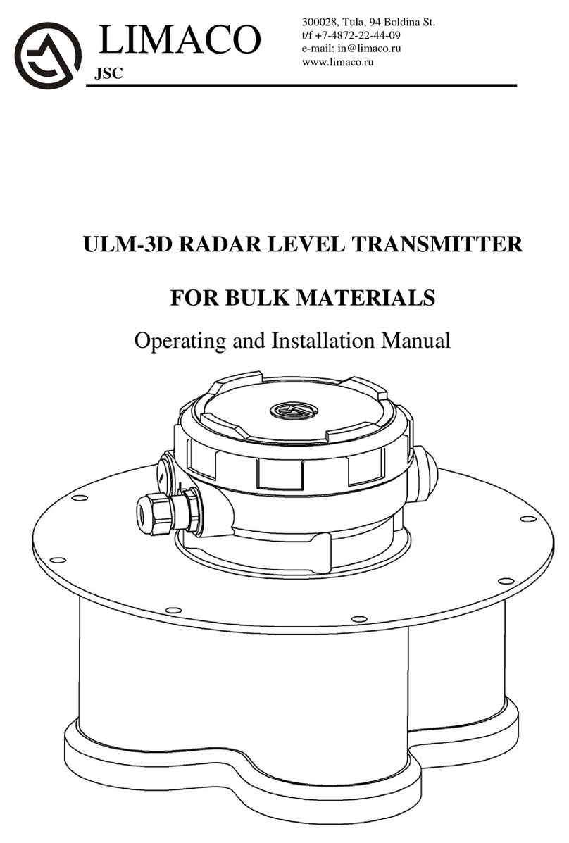
Limaco ULM-31-HF Specification sheet

OPERATION AND INSTALLATION MANUAL
RADAR NON-CONTACT LEVEL TRANSMITTERS
ULM-31-HF, ULM-31-HF-F, ULM-31А1,
ULM-31А1-HF, ULM-31А1-HF-F,
ULM-31А1-HF-F-LC.

2
ULM.0.01.000RE_10_08_20
CONTENTS
1
Document Details
1.1
Document Purpose ……………………………………............
5
1.2
Target Group ………………………………………………….
5
1.3
Symbolic Notations ……………………………………..........
5
2
Basic Safety Regulations
2.1
Requirements for Personnel …………………………………..
6
2.2
Purpose ……………………………………………………….
6
2.3
Operational Safety …………………………............................
8
2.4
General Guidelines on Safety ………………………………...
8
2.5
Environmental Safety ………………………………………...
8
3
Product Description
3.1
Level Transmitter Scope of Supply ………………………......
9
3.2
Product Design ……………………………………………….
10
3.3
Product Identification ………………………………………...
12
3.4
Operating Principle …………………………………………...
14
3.5
Packaging, Transportation and Storage ………………............
16
4
Installation
4.1
Selection of Installation Position ……………………………..
17
4.2
General Requirements for Installation on Mounting Pipe
Branch ………………………………………………………...
23
4.3
Mounting Branch Pipes ………………………………………
24
4.4
Measuring Beam Zone of Action ………………………….....
25
4.5
Dead Zone ……………………………………………….........
26
4.6
Examples for Installation ……………………………………..
27
4.7
Structures in Tank …………………………………………….
29

3
ULM.0.01.000RE_10_08_20
5
Electrical Connection
5.1
General Guidelines …………………………………………...
30
5.2
Connecting Cable …………………………………………….
30
5.3
Shielding and Earthing ……………………………………….
31
5.4
Purpose of Terminals. Connection. …………………………..
32
5.5
Power supply …………………………………………............
38
5.6
Device Connection Procedure ………………………………..
40
6
Initial Setup and Commissioning
6.1
Level Transmitter Address Setup …………………………….
43
6.2
Connection to PC via interface RS-485 ………………………
44
6.3
Setup of Device Basic Parameters using PC via RS-485 …….
47
6.4
Current Output 4-20 mA. Setup of Emergency Signals………
52
6.5
Setup of On-Off Signals ……………………………………...
54
6.6
Bluetooth ……………………………………………………..
56
7
Information on Device Operation
7.1
Device Diagnostics …………………………………………...
57
7.2
Output Signal Emulation ……………………………………..
59
7.3
Snapshots ……………………………………………………..
59
8
Trouble-Shooting …………....................................................
60
9
Maintenance …………………………………………………
64
10
Dismantling
10.1
Dismantling Procedure ……………………………………….
65
10.2
Disposal ………………………………………………………
65
11
Repair ………………………………………………………..
66
12
Appendices
12.1
Technical Specifications ……………………………………...
67
12.2
Specifications of levelmeter ULM-31A1-HF-F-LC, 2-wire
option………………………………………………………….
70

4
ULM.0.01.000RE_10_08_20
12.3
Mounting dimensions of level transmitter without mounting
flange …………………………………………………….
72
12.4
Level Transmitter Connection to Mounting Flange …………
72
12.5
Mounting of ULM-31А1 level transmitter at the stub tube ….
74
12.6
Mounting of ULM-31-HF-F, ULM-31А1-HF-F, ULM-31А1-
HF-F-LC level transmitters at the stub tube …………………
75
12.7
Mounting of ULM-31-HF, ULM-31А1-HF level transmitters
at the stub tube ……………………………………………….
76
12.8
Mounting of ULM-31А1 level transmitter at the stub tube
with insulating spacer………………………………………..
77
12.9
Mounting of ULM-31-HF-F, ULM-31А1-HF-F, ULM-31А1-
HF-F-LC level transmitters at the stub tube with insulating
spacer ………………………………………………………...
78
12.10
Mounting of ULM-31А1, ULM-31-HF-F, ULM-31А1-HF-F,
ULM-31А1-HF-F-LC level transmitters at the stub tube with
insulating spacer with the use of clamping flange …..……….
79
12.11
Mounting of ULM-31-HF, ULM-31А1-HF level transmitters
at the stub tube with insulating spacer with the use of clamp-
ing flange……………………………………………….........
80
12.12
Mounting of ULM-31-HF-F, ULM-31А1-HF-F, ULM-31А1-
HF-F-LC level transmitters at the small diameter stub tube
with the use of reducing piece………………………………...
81
12.13
Sealing ………………………………………………..............
82
12.14
Mounting Flange ………………………………….................
83
12.15
Design ………………………………………………………...
84

5
ULM.0.01.000RE_10_08_20
1 DOCUMENT DETAILS
1.1 Document Purpose
This Operation Manual includes information necessary for installation, connection,
commissioning and setup, as well as guidelines on maintenance and trouble-
shooting. Prior to the level transmitter installation and putting in operation it is nec-
essary to familiarize with instructions set forth herein.
1.2 Target Group
This Operation Manual is intended for the trained personnel carrying out the level
transmitter installation, commissioning, diagnostics and servicing. The personnel
shall know and observe the instructions set forth herein.
1.3 Symbolic Notations
Symbol
Meaning
Failure to observe the instruction may make the de-
vice inoperative or result in its incorrect operation.
Failure to observe the instruction may cause the
damage to personnel and/or device.
The symbol designates the useful information that
should be taken into account.
!CAUTION
!WARNING
NOTE

6
ULM.0.01.000RE_10_08_20
2BASIC SAFETY REGULATIONS
2.1 Requirements for Personnel
The personnel carrying out the level transmitter installation, commissioning, diag-
nostics and servicing shall study this Manual and be permitted to operate the device.
When operating the equipment, the personnel shall use the required personal protec-
tion equipment in compliance with the standards at the enterprise.
2.2 Purpose
The level transmitters ULM-31А1, ULM-31-HF, ULM-31А1-HF, ULM-31-HF-F,
ULM-31А1-HF-F and ULM-31А1-HF-F-LC (hereinafter referred to as the “level
transmitters”) are designed to continuously contactlessly measure the level of liquid,
viscous or bulky products and intended for use in the process metering systems. The
level transmitters are used for measuring the level in the closed and open tanks and
suit for metering a wide range of products, such as acids, alkalies, water solutions,
food products, cement, coal, etc. Unintended use of device can result in the emer-
gency situation at the production facility, put the device out of operation and can be
the potential hazard source.
Specification of all models of levelmeters of series ULM-31 there are in the table 1.
31A1
31A1-HF
31-HF
31-HF-F
31A1-HF-F
31A1-HF-F-LC
option 1
31A1-HF-F-LC
option 2
31A1-HF-F-LC
2-wire option
Radiation frequency,
GHz
24
125±5
125±5
125±5
125±5
125±5
125±5
125±5
Body appearance
Pic.
3.2
Pic. 3.1
Pic.
3.1
Pic. 3.3
Pic.
3.3
Pic. 3.3
Pic. 3.3
Pic. 3.3
Measuring range,m
0,6-30
(50)
0,6-30
(50)
0,6-30
(50)
0,6-30
(50)
0,6-30
(50)
0,6-15
0,6-15
0,6-15
Absolute measuring
error, mm
3
3
1*
1*
3
5
5
5
Antenna pattern, de-
gree
9
2
2
4
4
5
5
5
Bluetooth
+
+
+
+
+
+
+
-
RS-485
+
+
+
+
+
-
+
-
Relay outputs
+
+
+
+
+
-
-
-

7
ULM.0.01.000RE_10_08_20
31A1
31A1-HF
31-HF
31-HF-F
31A1-HF-F
31A1-HF-F-LC
option 1
31A1-HF-F-LC
option 2
31A1-HF-F-LC
2-wire option
Analog output 4-20
ma
+
+
+
+
+
+
+
+
Maximal power con-
sumption,W
6
6
6
6
6
6
6
0,8
Minimal number of
wires
4
4
4
4
4
4
4
2
Body
material
Alumi-
nium cast-
ing alloy
+
+
+
+
+
+
+
+
Polyamide
+
+
+
+
+
+
+
+
Configuration by
HART-modem
+
+
+
+
+
+
+
+
Configuration by
HART-
communicator
+
+
+
+
+
+
+
-
Getting readings by
HART
+
+
+
+
+
+
+
-
Produced now
+
+
+
+
+
-
+
+
Recommended ap-
plication
Tech-
nologi-
cal
con-
trol,liq
uid and
bulk
pro-
ducts
Techno-
logical
control,
liquid
and bulk
products
High
preci-
sion ac-
count-
ting, liq-
uid and
bulk
products
High
preci-
sion
ac-
count-
ting,
liquid
pro-
ducts
Tech-
nologi-
cal con-
trol,liqu
id pro-
ducts
Techno-
logical
control
,liquid
products
Techno-
logical
control,
liquid
products
Technolo-
gical con-
trol
,liquid
products
Connection type
Flange,
not less
than
DN100
Flange,
not less
than
DN80
Flange,
not less
than
DN80
Flange,
not less
than
DN50
Flange,
not less
than
DN50
Flange,
not less
than
DN50
Flange,
not less
than
DN50
Flange, not
less than
DN50
* 0,6 –30 m –+/- 1mm; 30 –50 m –+/- 3mm.
Table 1 –Specifications of all models of levelmeters of ULM-31 series.

8
ULM.0.01.000RE_10_08_20
2.3 Operational Safety
The device operational safety is ensured only in compliance with these manual
guidelines. To ensure operational safety and to observe the guarantee obligations, it
is prohibited to make any modifications in the device design. The operations with
the devices, except those set forth in this manual, can be performed only after the
manufacturer's official authorization.
2.4 General Guidelines on Safety
The level transmitters ULM-31А1, ULM-31-HF, ULM-31-HF-F, ULM-31А1-HF,
ULM-31А1-HF-F and ULM-31А1-HF-F-LC satisfy all current safety requirements
and standards. Depending on the version, the working emission frequency of the
level transmitters makes approximately 24 GHz for ULM-31А1 and 125±5 GHz for
ULM-31-HF, ULM-31-HF-F, ULM-31А1-HF, ULM-31А1-HF-F and ULM-31А1-
HF-F-LC. The emission power does not exceed 8 mW, which is significantly lower
than than the threshold limit values. The level transmitter is completely safe for the
human and the animals. To avoid the emergency situations at the production facili-
ty, it is allowed operating the device only in good working order. The level trans-
mitters are allowed for use only in the explosion-proof area.
2.5 Environmental Safety
Compliance with recommendations set forth in Sections “Packaging, Transportation
and Storage” and “Disposal” contributes to environmental protection.

9
ULM.0.01.000RE_10_08_20
3 PRODUCT DESCRIPTION
3.1 Level Transmitter Scope of Supply.
The scope of supply includes:
- The radar level transmitter (ULM-31-HF, ULM-31А1, ULM-31А1-HF, ULM-31-
HF-F, ULM-31А1-HF-F, ULM-31А1-HF-F-LC);
- The setup software and the documentation on electronic medium (compact disk
CD):
- The software program for Ulmcfg setup;
- The driver SW (Bluetooth, HART);
- The Operation Manual;
- The additional documentation (certificates and permits, the other technical
information, if necessary).
The software and the documentation on electronic medium can be supplied in the
amount of 1 pc for the whole order complete set according to specification.
The auxiliary equipment that may be included in the order specification:
- The upper level software:
“Limaco OPC Server”;
OPC Client –“Reservoir Viewer” measuring system visualization;
- power supply;
- interface RS-485 converters;
- interface HART converters;
- configurator's control panel PL-01;
- sealing gasket;
- adapting flange.
The particular type of auxiliary equipment (interface adapters, flanges, sealing gas-
kets) may be of different design; it is agreed during the equipment order and is spec-
ified in the order specification.
One of adapting flange variants - temporary flange is given in paragraph 12.14.
NOTE
NOTE

10
ULM.0.01.000RE_10_08_20
3.2 Product Design
Fig. 3.1. Basic elements appearance and location for the level transmitters
ULM-31-HF, ULM-31А1-HF.
Fig. 3.2. Basic elements appearance and location for the level transmitter
ULM-31А1.

11
ULM.0.01.000RE_10_08_20
Fig. 3.3. Basic elements appearance and location for the level transmitters
for the level transmitters ULM-31-HF-F, ULM-31А1-HF-F and ULM-31А1-HF-F-
LC. Aluminium case.
Fig. 3.4. Basic elements appearance and location for the level transmitters
for the level transmitters ULM-31-HF-F, ULM-31А1-HF-F and ULM-31А1-HF-F-
LC. Plastic case.

12
ULM.0.01.000RE_10_08_20
Fig. 3.5. Level Transmitter Design. Electronic Module Location.
3.3 Product Identification
The device identification is performed using one of possible methods:
- according to the data specified on the device nameplate (identifying plate);
- according to the attached device certificate;
- by the request to the manufacturer with specification of the level transmitter serial
numbers.
The level transmitter common-type identifying plate includes the following data for
the device identification and use:
- manufacturer's logo;
- device type;
- serial number;
- year of manufacture;
- conformance mark;
- protection rating IP;
- environment permissible temperature;
- supply voltage;
- output signals.
Electronic module

13
ULM.0.01.000RE_10_08_20
Examples of the common-type nameplates:
Fig. 3.6. Common-type nameplate ULM-31-HF
Fig. 3.7. Common-type nameplate ULM-31A1
Fig. 3.8. Common-type identifying plate ULM-31A1-HF
Fig. 3.9. Common-type identifying plate ULM-31A1-HF-F
Fig. 3.10. Common-type identifying plate ULM-31A1-HF-F-LC
Fig. 3.11. Common-type identifying plate ULM-31-HF-F

14
ULM.0.01.000RE_10_08_20
3.4 Operating Principle
The level transmitter is installed on the tank roof, onto the pipe branch flange.
However, no transmitter’s part is dipped inside the tank. The device measures the
distance
L
from the antenna shield (para. 12.13) to the product surface via the
opening in the flange. Then the computation of the level is carried out by the formu-
la
LHU
, where
H
is the installation height.
The reference plane of the level transmitter measuring range is the antenna shield
lower surface.
Fig. 3.12. Level Transmitter on Tank.
The radar level transmitter antenna sends out the radio signal and receives the echo-
signal reflected from the product surface. Using the software-hardware system, the
electronic unit processes the echo-signal and converts it to the corresponding output
signal, which carries the information on the measured value.
Distance (L)
Level (U)
Height (H)

15
ULM.0.01.000RE_10_08_20
Fig. 3.13. Measuring Principle.
The level transmitters uses a FMCW principle of operation—the radio locator prin-
ciple. This is one of classical methods for non-contact measuring of the distance,
which allows minimizing the effect of stray interferences and interferences related
to irregularities (disturbances) of the measured product surface.
Operating principle consists in the following: low-power micro wave generator
generates sounding radio signal, with its frequency growing linearly during the
measuring period (solid line in Fig.3.14). This signal (let us call it direct one) is sent
by the sensor antenna in the product surface direction. After delay time
Td
, the sig-
nal reflected from the surface (the dashed line in Fig. 3.14) returns to antenna.
Td
–
the time required for the radio wave to travel the distance from antenna to the re-
flecting surface and back. Td= 2·L/s, where s–the light speed. As far as the veloci-
ty of radio wave propagation is constant, so, knowing the time delay, it is possible
to determine the traveled distance. Fig. 3.6 shows, that during the time
Td
, the fre-
quency of direct signal will increase by
F
. During mixing direct and reflected sig-
nals, the low-frequency signal of differential frequency is separated out
F
. Further
on, this signal is digitized and process by the signal processor (DSP). Using the al-
gorithm based on Fourier transformation and the original adaptive algorithms for
processing and noise suppression, DSP carries out the signal spectral analysis re-
sulting in precise value of differential frequency. Having determined this frequency,
we shall determine the signal time delay, and therefore, the distance traveled by the
radio wave. Further on the measured distance is used for calculation of the level and
the volume.

16
ULM.0.01.000RE_10_08_20
Fig. 3.14. LFM-radio locator operating principle
3.5 Packaging, Transportation and Storage
The level transmitter is supplied in the package, which ensures its protection during
transportation.
The package is made of cardboard, which is a recyclable material. In certain cases it
is possible to use polyethylene foam and polyethylene film, which are disposed of at
dedicated processing enterprises.
The device transportation shall be carried out in the original package. After trans-
portation the device shall be inspected for available transport damages and com-
pleteness of set. In case of detecting any transport damages or incompleteness of
set, all revealed defects are documented in the established order.
Prior to installation, the devices shall be stored in the original closed packages.
During storage, the following conditions shall be complied with:
- storage temperature - 40…+80˚С;
- relative humidity - 20…85%;
- storage under effect of aggressive environment is not allowed;
- no storage in the open air is allowed;
- during storage, no mechanical impact on the device is allowed.
.

17
ULM.0.01.000RE_10_08_20
4. INSTALLATION
4.1 Selection of Installation Position
The level transmitter stability of readings and the product precision of measuring
depend on its correct installation.
When selecting the installation position, the following recommendations should be
adhered to:
- to install the device in such way that in the measurement zone there are no sub-
jects and structures making interferences to the radio wave beam propagation
(pipes, valves, stirrers, tank walls, etc. For details, see para4.4);
Fig. 4.1. Device Installation on Tank. Structural Elements
- the device should not be installed in such way that the stream of the product filling
up the tank makes in the beam action zone. The device shall be located in an opti-
mum manner away from the feeding area;

18
ULM.0.01.000RE_10_08_20
Fig. 4.2. Device Installation on Tank. Product Feeding.
- during product discharge from the tank, the swirl can be formed on the product
surface. This shall be considered when selecting the device location. The level
transmitter shall be installed above the location with the smoothest product surface.
Fig. 4.3. Device Installation on Tank. Product Discharge.

19
ULM.0.01.000RE_10_08_20
- to provide the level measurement over the total depth of the tank, the level trans-
mitter shall be oriented in direction of the tank lowest point. In the vertical cylindri-
cal hoppers with the cone-shaped outlet, this is achieved by its installation in the
center of the hopper roof.
Fig. 4.4. Device Installation on Hopper with Cone-Shaped Bottom.
In case such way of installation is impossible, it is necessary to direct the device
measuring beam to the hopper center, which is achieved by inclining the mounting
pipe branch flange plane.
The required inclination angle
depends on installation position and the hopper
dimensions. The inclination angle can be checked using the inclination angle sensor
built in the level transmitter or using the level (For details, see para. 7.1 “Device
Diagnostics”).

20
ULM.0.01.000RE_10_08_20
Fig. 4.5. Device Installation with Inclination on Hopper with Cone-Shaped Bottom.
The values of distances
V
from the tank center to installation position are given in
the following Table.
Installation
height
H
, m
2
4
6
8
10
2
0.1
0.1
0.2
0.3
0.4
4
0.1
0.3
0.4
0.6
0.7
6
0.2
0.4
0.6
0.8
1.1
8
0.3
0.6
0.8
1.1
1.4
10
0.3
0.7
1.1
1.4
1.8
15
0.5
1.0
1.6
2.1
2.6
20
0.7
1.4
2.1
2.8
3.5
25
0.9
1.7
2.6
3.5
4.4
30
1.0
2.1
3.2
4.2
5.3
35
1.2
2.4
3.7
4.9
6.2
40
1.4
2.8
4.2
5.6
7.1
45
1.6
3.1
4.7
6.3
7.9
50
1.7
3.5
5.3
7.0
8.8
This manual suits for next models
5
Table of contents
Other Limaco Transmitter manuals
Popular Transmitter manuals by other brands

Thorne & Derrick
Thorne & Derrick rotronic CF3-W-US installation manual

NEC
NEC DSV-8- Series Brochure & specs

JUMO
JUMO B 90.7027.1 operating instructions

Sony
Sony TMR-BT8iP - Bluetooth Wireless Transmitter operating instructions

Novatech
Novatech 1732 Operator's manual

Kobold
Kobold LCI operating instructions