manuals.online logo
Brands
  1. Home
  2. •
  3. Brands
  4. •
  5. MG
  6. •
  7. Transmitter
  8. •
  9. MG M6SWVS User manual

MG M6SWVS User manual

EM-7977 Rev.5 P. 1 / 4
MG CO., LTD. www.mgco.jp
5-2-55 Minamitsumori, Nishinari-ku, Osaka 557-0063 JAPAN
INSTRUCTION MANUAL
SIGNAL TRANSMITTER
(two isolated outputs) MODEL M6SWVS
BEFORE USE ....
Thank you for choosing us. Before use, please check con-
tents of the package you received as outlined below.
If you have any problems or questions with the product,
please contact our sales office or representatives.
■PACKAGE INCLUDES:
Signal conditioner ...............................................................(1)
■MODEL NO.
Confirm Model No. marking on the product to be exactly
what you ordered.
■INSTRUCTION MANUAL
This manual describes necessary points of caution when
you use this product, including installation, connection and
basic maintenance procedures.
POINTS OF CAUTION
■CONFORMITY WITH EU DIRECTIVES OR UL
• The equipment must be mounted inside a panel.
• The actual installation environments such as panel con-
figurations, connected devices, connected wires, may af-
fect the protection level of this unit when it is integrated
in a panel system. The user may have to review the CE
requirements in regard to the whole system and employ
additional protective measures to ensure the CE conform-
ity.
• Install lightning surge protectors for those wires connect-
ed to remote locations.
■POWER INPUT RATING & OPERATIONAL RANGE
• Locate the power input rating marked on the product and
confirm its operational range as indicated below:
24V DC rating: 24V ±10%, approx. 0.6W
■GENERAL PRECAUTIONS
• Before you remove the unit or mount it, turn off the power
supply and input signal for safety.
■ENVIRONMENT
• Indoor use.
• When heavy dust or metal particles are present in the
air, install the unit inside proper housing with sufficient
ventilation.
• Do not install the unit where it is subjected to continuous
vibration. Do not subject the unit to physical impact.
• Environmental temperature must be within -20 to +55°C
(-4 to +131°F) with relative humidity within 30 to 90%
RH in order to ensure adequate life span and operation.
■WIRING
• Do not install cables close to noise sources (relay drive
cable, high frequency line, etc.).
• Do not bind these cables together with those in which
noises are present. Do not install them in the same duct.
■AND ....
• The unit is designed to function as soon as power is sup-
plied, however, a warm up for 10 minutes is required for
satisfying complete performance described in the data
sheet.
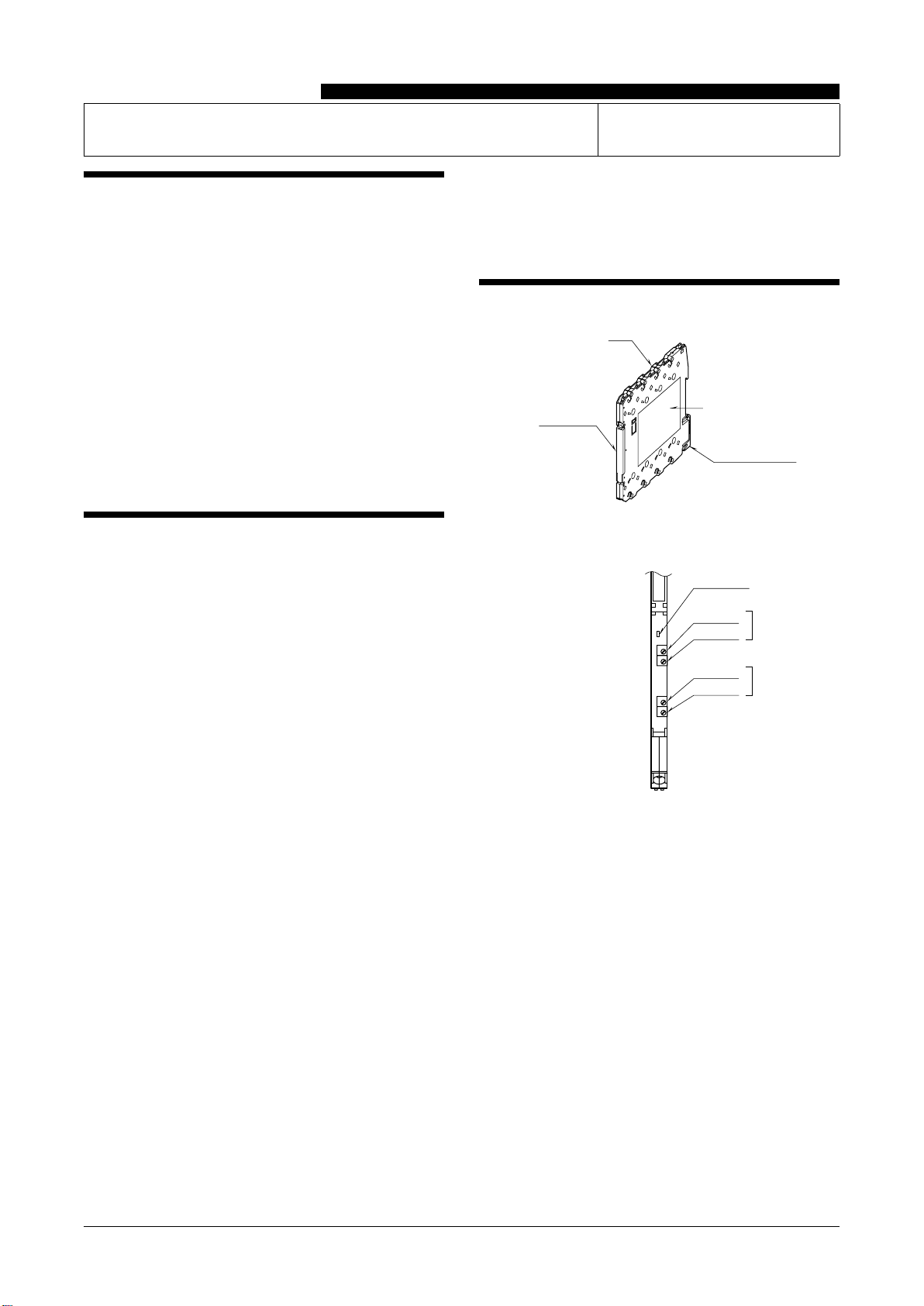
COMPONENT IDENTIFICATION
Body
Front Cover
DIN Rail Adaptor
Specifications
■FRONT VIEW (with the cover open)
Zero Adj.
Power LED
Span Adj. Output 1
Zero Adj.
Span Adj. Output 2
M6SWVS
EM-7977 Rev.5 P. 2 / 4
MG CO., LTD. www.mgco.jp
5-2-55 Minamitsumori, Nishinari-ku, Osaka 557-0063 JAPAN
INSTALLATION
Set the unit so that its DIN rail adapter is at the bottom. When the unit is installed to an Installation Base (model M6SBS),
refer to its instruction manual.
■MOUNTING THE UNIT ON A DIN RAIL
A)Hang the upper hook at the rear side of unit on the DIN
rail.
B)Push in the lower in keeping pressing the unit to the DIN
rail.
ADIN Rail
B
■REMOVING THE UNIT
A)Pull down the DIN rail adaptor using a minus screwdriv-
er.
B)Pull out the lower part of the unit.
C)Remove the upper part from the DIN rail.
A
DIN Rail Adaptor
CB
TERMINAL CONNECTIONS
Connect the unit as in the diagram below or refer to the connection diagram on the side of the unit.
■EXTERNAL DIMENSIONS unit: mm (inch)
94 (3.70)
5.9 (.23)
DIN RAIL
35mm wide
DIN RAIL HOOK
*Use a minus screwdriver: tip width 3.8 mm max., tip thickness 0.5 to 0.6 mm
102 (4.02)
[0.5 (.02)]
SCREWDRIVER
INSERTION ANGLE
: approx. 40°
WIRE INSERTION ANGLE
: approx.35°
TEST PROBE
max. 2 (.08) dia.
SCREWDRIVER
*
INSERTION ANGLE
: approx. 35°
5678
1234
• When mounting, no extra space is needed between units.
M6SWVS
EM-7977 Rev.5 P. 3 / 4
MG CO., LTD. www.mgco.jp
5-2-55 Minamitsumori, Nishinari-ku, Osaka 557-0063 JAPAN
■CONNECTION DIAGRAM
+
–
7
+
–
INPUT
3
4
POWER
+
–
OUTPUT 1
5
6
+
–
1
2
OUTPUT 2
The section enclosed by broken line is only with
2nd output option.
POWER
CONNECTOR
8
■WIRING INSTRUCTIONS
• Applicable wire size
Solid: 0.2 to 2.5 mm2(0.55 to 1.75 dia.)
Stranded: 0.2 to 2.5 mm2(Tinning wire ends may
cause contact failure and therefore is not
recommended.)
Ferruled: 0.2 to 1.5 mm2(0.55 to 1.35 dia.)
• Expose wire conductors by 8 mm (0.31”).
Expose 8 mm
• How to Connect Wires
Screwdriver
Wire
1) Insert a minus screwdriver into the wire entry opening,
between the clamp and the housing, until its tip hits the
bottom where it is firmly held.
Tension Clamp
Screwdriver
2) Insert a wire. Push the screwdriver toward the direction
indicated with the arrow in the figure below to widen the
opening if necessary.
Wire Entry
Wire
3) Confirm that the wire tip hits the bottom and pull out the
screwdriver in holding it in position.
Confirm that the wire’s insulation tube is not caught in
the clamp.
M6SWVS
EM-7977 Rev.5 P. 4 / 4
MG CO., LTD. www.mgco.jp
5-2-55 Minamitsumori, Nishinari-ku, Osaka 557-0063 JAPAN
CHECKING
1) Terminal wiring: Check that all cables are correctly con-
nected according to the connection diagram.
2) Confirm that the wire insulation tubes are not caught in
the clamp.
3) Power input voltage: Check voltage across the terminal
7 – 8 with a multimeter.
4) Input: Check that the input signal is within 0 – 100% of
the full-scale.
5) Output: Check that the load resistance meets the de-
scribed specifications.
ADJUSTMENT PROCEDURE
This unit is calibrated at the factory to meet the ordered
specifications, therefore you usually do not need any cali-
bration.
For matching the signal to a receiving instrument or in case
of regular calibration, adjust the output as explained in the
following.
■HOW TO CALIBRATE THE OUTPUT SIGNAL
Use a signal source and measuring instruments of sufficient
accuracy level. Turn the power supply on and warm up for
more than 10 minutes.
1) ZERO: Apply 0% input and adjust output to 0%.
2) SPAN: Apply 100% input and adjust output to 100%.
3) Check ZERO adjustment again with 0% input.
4) When ZERO value is changed, repeat the above proce-
dure 1) – 3).
5) Go through the same procedure for the Output 2.
MAINTENANCE
Regular calibration procedure is explained below:
■CALIBRATION
Warm up the unit for at least 10 minutes. Apply 0%, 25%,
50%, 75% and 100% input signal. Check that the output
signal for the respective input signal remains within accu-
racy described in the data sheet. When the output is out of
tolerance, recalibrate the unit according to the “ADJUST-
MENT PROCEDURE” explained earlier.
LIGHTNING SURGE PROTECTION
We offer a series of lightning surge protector for protec-
tion against induced lightning surges. Please contact us to
choose appropriate models.

Other MG Transmitter manuals

MG Mini-M M2VF3 User manual

MG

MG Mini-M M2VF3 User manual

MG 10AC User manual

MG

MG 10AC User manual

MG Mini-M M2CA User manual

MG

MG Mini-M M2CA User manual

MG M6DCTC User manual

MG

MG M6DCTC User manual

MG BCT User manual

MG

MG BCT User manual

MG FRT User manual

MG

MG FRT User manual

MG Mini-M M2EXV User manual

MG

MG Mini-M M2EXV User manual

MG M60EWVS User manual

MG

MG M60EWVS User manual

MG W5LCS User manual

MG

MG W5LCS User manual

MG 10RS User manual

MG

MG 10RS User manual

MG M3-UNIT Series User manual

MG

MG M3-UNIT Series User manual

MG M3SVS User manual

MG

MG M3SVS User manual

MG M6NVF User manual

MG

MG M6NVF User manual

MG M6SXM User manual

MG

MG M6SXM User manual

MG W5VS User manual

MG

MG W5VS User manual

MG 17PE User manual

MG

MG 17PE User manual

MG M6NPA User manual

MG

MG M6NPA User manual

MG 10JRE User manual

MG

MG 10JRE User manual

MG Mini-M M2TS User manual

MG

MG Mini-M M2TS User manual

MG KWRS2 User manual

MG

MG KWRS2 User manual

MG M6NWVS User manual

MG

MG M6NWVS User manual

MG W5TS User manual

MG

MG W5TS User manual

MG M3-UNIT Series User manual

MG

MG M3-UNIT Series User manual

MG HR User manual

MG

MG HR User manual

Popular Transmitter manuals by other brands

Mobatime WTD 868-T-V2 instruction manual

Mobatime

Mobatime WTD 868-T-V2 instruction manual

Technalogix TAVD-100H Operation manual

Technalogix

Technalogix TAVD-100H Operation manual

COBHAM SOLH264TX user guide

COBHAM

COBHAM SOLH264TX user guide

Thermo Scientific ALPHA COND 500 - REV 4 manual

Thermo Scientific

Thermo Scientific ALPHA COND 500 - REV 4 manual

PR electronics PRetop 5334 Safety instructions

PR electronics

PR electronics PRetop 5334 Safety instructions

Valor ACC-FMT7 Installation

Valor

Valor ACC-FMT7 Installation

Rosemount 248 Reference manual

Rosemount

Rosemount 248 Reference manual

Canon WFT-R10 Advanced user's guide

Canon

Canon WFT-R10 Advanced user's guide

Siemens Sitrans LR250 Compact operating instructions

Siemens

Siemens Sitrans LR250 Compact operating instructions

jotron TA-7650C Maintenance and Repair Manual

jotron

jotron TA-7650C Maintenance and Repair Manual

AMG AMG4783RN-CWDMn instruction manual

AMG

AMG AMG4783RN-CWDMn instruction manual

Omnitronic UHF-400 BP user manual

Omnitronic

Omnitronic UHF-400 BP user manual

Oregon Scientific RT918 user manual

Oregon Scientific

Oregon Scientific RT918 user manual

REL 518-D instruction manual

REL

REL 518-D instruction manual

Becker Centronic SunWindControl SWC441-II Assembly and operating instructions

Becker

Becker Centronic SunWindControl SWC441-II Assembly and operating instructions

CAMDEN Lazerpoint CM-TXLF Series installation instructions

CAMDEN

CAMDEN Lazerpoint CM-TXLF Series installation instructions

Heathkit SB-401 Assembly manual

Heathkit

Heathkit SB-401 Assembly manual

CMOSTEK CMT2150A manual

CMOSTEK

CMOSTEK CMT2150A manual

manuals.online logo
manuals.online logoBrands
  • About & Mission
  • Contact us
  • Privacy Policy
  • Terms and Conditions

Copyright 2025 Manuals.Online. All Rights Reserved.