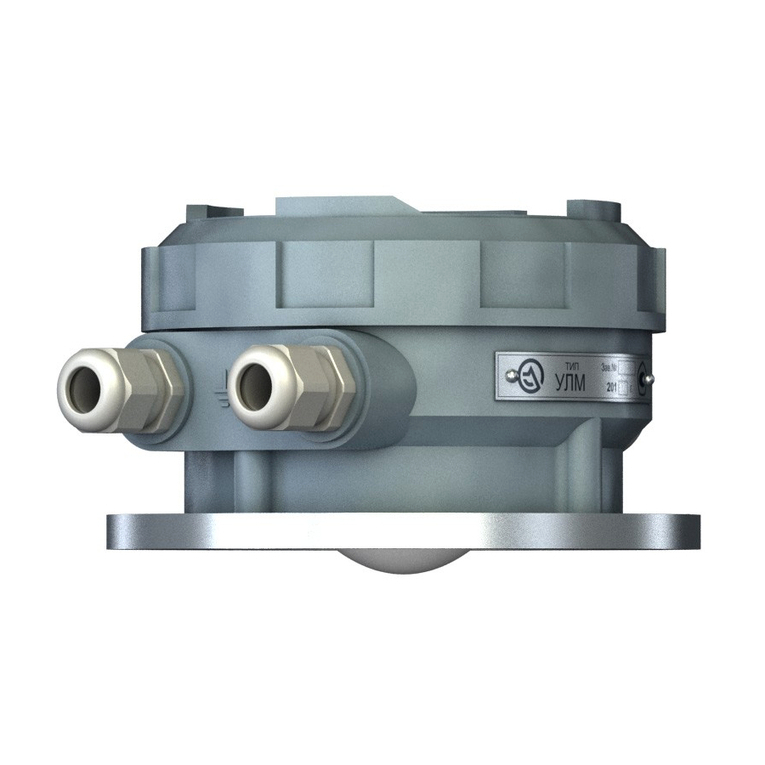
Limaco ULM-3D Series Specification sheet

ULM-3D RADAR LEVEL TRANSMITTER
FOR BULK MATERIALS
Operating and Installation Manual
300028, Tula, 94 Boldina St.
t/f +7-4872-22-44-09
e-mail: in@limaco.ru
www.limaco.ru
LIMACO
JSC

TABLE OF CONTENTS
1 Document Info
1.1 Purpose……………………………………………………….. 5
1.2 Target group…………………………………………………... 5
1.3 Symbols …………………………………………………….... 5
2 Safety basics
2.1 Personnel requirements………………………………………. 6
2.2 Purpose ………………………………………………………. 6
2.3
Operational safety ……………………………………………. 6
2.4 General safety guidelines……………………………………... 7
2.5 Environmental safety ………………………………………… 7
3 Product description
3.1 ULM-3D scope of supply….…………………………………. 7
3.2 Product design ……………………………………………….. 8
3.3 Product identification ………………………………………… 9
3.4 Operation concept ……………………………………………. 9
3.5
ULM-3D-5 operation specifics………………………….......... 12
3.6 Acceptance, packaging, transportation, and storage rules
…………………………………………………………………
14
4 Installation
4.1 General recommendations for level transmitter placement
…………………………………………………........................
15
4.2 Position for installation ………………………………………. 19
4.3 Requirements for the installation on mounting nozzle for
ULM-3D-5 …………………………………………….……...
20
4.4 Requirements for the installation on mounting nozzle for
ULM-3D-1 …………………………………………….……...
20
4.5 Measurement beam coverage ………………………………… 21
4.6 Blind spot …………………………………………………….. 21
2
RE_ULM3DX_18_02_20

4.7 Installation examples for ULM-3D-5………………………… 22
4.8 Installation examples for ULM-3D-1………………………… 23
5 Electrical connection
5.1 General instructions…………………………………………... 25
5.2 Connection cable ……………………………………………... 25
5.3 Shielding and earthing ……………………………………….. 26
5.4 Pin assignment. Connection. …………………………………. 27
5.5 Power supply …………………………………………………. 30
5.6 How to connect the device …………………………………… 31
6 Initial setup and commissioning
6.1 Level transmitter address setup ………………………………. 34
6.2 PC connection via RS-485……………………………………. 35
6.3
Setting key parameters of level transmitter using PC via RS-
485 …………………………………………………………….
37
7Troubleshooting 39
8
The structure of volume measurement system ………………..
43
9
Brief description of the initial master software setup…………
45
10 Maintenance ………………………………………………… 48
10.1 Preventive inspection, preventive maintenance ………………
48
10.2 Preventive inspection with the removal of level transmitter,
preventive maintenance ……………………………..………..
48
11
Dismantling
11.1 Dismantling procedure ……………………………………….. 48
11.2 Disposal ………………………………………………………. 49
12 Repair………………………………………………………... 49
13 Appendices
13.1 Technical specifications………………………………………. 50
13.2 Level transmitter connection to the mounting flange and over-
all dimensions of ULM-3D-5 ……………………….………..
53
13.3 Level transmitter connection to the mounting flange and over-
3
RE_ULM3DX_18_02_20

all dimensions of ULM-3D-5 ……………………….………..
54
13.4 Handling of cable gland ……………………………………… 56
4
RE_ULM3DX_18_02_20

1 DOCUMENT INFO
1.1 Purpose
This operating manual contains information necessary for installation, connection,
commissioning, and configuration, as well as instructions for maintenance and
Troubleshooting. Please read the instructions provided here before the installation
and commissioning of the level transmitter.
1.2 Target group
This operating manual is intended for trained personnel who perform installation,
commissioning, diagnostics, and maintenance of the level transmitter. The person-
nel shall know and follow the instructions provided in this document.
1.3 Symbols
Symbol
Description
Failure to follow the instructions may disable the
device or cause its malfunction.
Failure to follow the instructions may cause damage
to personnel and/or to the device.
The symbol indicates useful information that needs
attention.
!
ATTENTION
!
WARNING
NOTE
5
RE_ULM3DX_18_02_20

2SAFETY BASICS
2.1 Personnel requirements
Personnel who perform installation, commissioning, diagnostics, and maintenance
of the level transmitter shall read this manual and be admitted to work with the de-
vice. When working with equipment, personnel shall use the required personal pro-
tective equipment in accordance with the company's regulations.
2.2 Purpose
ULM-3D level transmitter is designed for continuous non-contact measurement of
the level of any bulk materials and is intended for use in process flow metering sys-
tems and product inventory management. ULM-3D level transmitter can be used to
measure the level and volume in tanks and open storage facilities. A system of mul-
tiple level transmitters can be used for large tanks and storage facilities. The soft-
ware package can display a three-dimensional picture of the measured material on a
remote computer.
The level transmitter marked Ex tb IIIC T85°C Db is intended for use in explosive
dust environments for conductive dust for installation in zones of class 21, 22 as per
GOST IEC 60079-10-2-2011.
Before using level transmitters in an explosion hazardous zone, make sure that the
version indicated on the nameplate corresponds to the one acceptable for use in this
zone.
Climatic category is О1 as per GOST 15150-69.
The level transmitter belongs to D3 group as per GOST R 52931-2008 in terms of
resistance to the influence of temperature and ambient air humidity.
Undue device application can result in occupational accident or device failure and is
a source of potential danger.
2.3 Operational safety
The operational safety of device is ensured only subject to the observation of in-
structions provided herein.
The level transmitter corresponds to safety integrity level 3 (SIL 3) as per GOST R
IEC 61508-1-2012, GOST R IEC 61511-1-2011.
Due to operational safety and warranty reasons, any modifications to the device de-
sign are prohibited. Any actions with the device other than those described in this
manual can only be performed with the official permission of the manufacturer. The
service life of level transmitters is 20 years.
6
RE_ULM3DX_18_02_20

2.4 General safety guidelines
ULM-3D level transmitter meets all modern requirements and safety standards.
The operating frequency of level transmitter is about 125 GHz. The radiation pow-
er does not exceed 8 MW, which is significantly lower than the maximum permissi-
ble values. The level transmitter is completely safe for humans and animals.
The device may be operated only in good working order to avoid occupational acci-
dents.
ULM-3D level transmitter without an explosion protection label may be used only
in an explosion-proof zone.
2.5 Environmental safety
Compliance with the recommendations provided in sections "Packaging, transporta-
tion, and storage" and "Disposal" contributes to environmental protection.
3. PRODUCT DESCRIPTION
3.1 ULM-3D scope of supply
The scope of supply includes:
- Radar level transmitter
- Documentation and software on electronic media:
- Ulmcfg setup and configuration software;
- Software for setup via Bluetooth for Android mobile operating system;
- Limaco OPC-server software;
- Multi Beam Radar Surface Plotter software;
- Operating and Installation Manual;
- Supplementary documentation (certificates and permits, if necessary, other
technical information).
1 piece of software and documentation on electronic media can be supplied for the
entire order as per the specification.
Optional equipment that can be included in the order specification:
- power supply;
- RS-485 interface converters;
- mounting kit.
The specific type of optional equipment (interface adapters, mounting products)
may have different versions. This is to be agreed when ordering the equipment and
stated in the order specification.
NOTE
NOTE
7
RE_ULM3DX_18_02_20

3.2 Product design
Fig. 3.1. Appearance and location of key ULM-3D-5 components
Fig. 3.2. Appearance and location of key ULM-3D-1 components
1 – aerial unit housing;
2 – mounting flange;
3 – cable gland or cable gland plug;
4 – electronic module housing;
5 – electronic module cover;
6 – Bluetooth module plug;
7 – aerial unit shield.
1
2
3
4
5
6
7
2
3
4
5
7
8
RE_ULM3DX_18_02_20

3.3 Product identification
The device is identified in one of the possible ways:
- as per the data specified on the device nameplate;
- as per the attached product data sheet;
- upon request to the manufacturer with the indication of level transmitter serial
numbers.
A standard level transmitter nameplate contains the following data for device identi-
fication and application:
- manufacturer's logo;
- device type;
- serial number;
- year of manufacture;
- IP rating;
- explosion protection marking;
- name of the certification body and number of the certificate of conformity;
- permissible ambient temperature;
- supply voltage;
- output signals.
An example of a standard nameplate is shown in Fig. 3.3
ОС ООО « ХХ Х »
№ ТС RU C-RU.АМ02.В. ХXXX
Fig. 3.3. Standard nameplate
Level transmitter designation system has the following form:
ULM-3D-Х, where
Х – level transmitter version: 1 – one measuring channel, 5 – measuring channels.
3.4 Operation concept
The level transmitter is installed above the measured surface of material. The device
is mounted in an opening on the tank roof using a flange in a closed tank (Fig. 3.4),
and using a special bracket in open tanks and storage facilities. The device measures
the distance Lifrom the bottom surface of mounting flange to the product surface
for each of the measuring channels. Then the level is calculated using the formula
Ui=H-Li *cos(ai), where H is the installation height, aiis the tilt angle of i-channel.
The base plane of the measuring range of level transmitter is the lower surface of
mounting flange (Fig. 3.1 item 2).
9
RE_ULM3DX_18_02_20

Fig. 3.4. ULM-3D-5 level transmitter on the tank
Radar level transmitter aerial system emits a radio signal with a frequency of about
125 GHz and receives an echo signal reflected from the product surface. The elec-
tronic unit processes the echo signal by means of a software and hardware complex
and converts it into a corresponding output signal that carries information about the
measured value.
1 – level transmitter;
2 – emitted signal;
3 – reflected signal;
4 – the surface of measured product.
Fig. 3.5. Measurement method
The level transmitter operates as a FMCW (Frequency Modulated Continuous
Wave) radar. This is one of conventional methods of non-contact distance mea-
surement, which minimizes the influence of spurious interference and interference
associated with irregularities (disturbances) of the surface of measured product.
The operation concept is as follows: a low-power microwave generator generates a
probing radio signal with linearly increasing frequency during the measurement pe-
H
Un
Ln
Li
Ui
L
1
2
3
4
10
RE_ULM3DX_18_02_20

riod (solid line in Fig.3.5). This signal (let's call it direct) is emitted by the level
transmitter aerial in the direction of product surface. After the delay time Td, the
signal reflected from the surface (the dotted line in Fig. 3.5) returns to the aerial Td
– the time a radio wave requires to travel the distance from the aerial to the reflect-
ing surface and back. Td=2L/s, where s is the speed of light. Since the speed of ra-
dio wave propagation is constant, if you know the delay time, you can derive the
distance traveled. Fig. 3.6 shows that during Td, the frequency of direct signal will
increase by ∆F. When mixing the direct and reflected signals, a low-frequency dif-
ference frequency signal ∆F is released. This signal is then digitized and processed
by a signal processor (DSP). Using a Fourier transform algorithm and original adap-
tive processing and noise reduction algorithms, the DSP performs a spectral analy-
sis of the signal that results in an accurate difference frequency value. By determin-
ing this frequency, we will derive the delay time of the signal, and therefore the dis-
tance traveled by the radio wave. Then the measured distance is used to calculate
the level.
Fig. 3.6. Operating concept of FMCW-radar
ULM-3D-5 level transmitter has 5 measuring channels. Each channel can be
oriented to a specific area on the product surface. Thus, the level transmitter has in-
formation on the level of measured product at 5 different points in the tank or sto-
rage facility.
.
11
RE_ULM3DX_18_02_20

Fig. 3.7. ULM-3D-1 level transmitter on the tank.
Уровень (U)
Level (U)
Расстояние (L)
Distance (L)
Высота установки (H)
Installation height (H)
ULM-3D-1 level transmitter has one measuring channel, which is always oriented
strictly along the vertical axis of level transmitter.
3.5 ULM-3D-3.5 operation specifics
The measuring channels of ULM-3D-5 level transmitter work in turn. The informa-
tion from each channel is processed by a microprocessor system that calculates the
distance to the product surface from each channel.
Each measuring channel has its own serial number; the numbering of channels is
shown in Fig. 3.8. Information from each measuring channel of the level transmitter
can be transmitted to the Multi Beam Radar Surface Plotter software, which builds a
model of the product surface profile and calculates the volume of measured material
taking into account the shape and dimensions of the tank.
Detailed description of the use of level transmitter channel numbering in the prod-
uct volume measurement system is given in cl. 9 of this description.
12
RE_ULM3DX_18_02_20

Fig. 3.8. Numbering of transmitter channels
The measuring beam of each channel is oriented to a specific area of the product
surface in the storage facility. Channel number 1 (central) is always oriented strictly
along the vertical axis of the level transmitter. Other channels are oriented based on
the specific application, see cl. 4.2 for more details.
Tilt angle relative to the vertical axis of the level transmitter for each measurement
channel is specified in the level transmitter data sheet. The direction of the measur-
ing beams of channels is shown in Fig. 3.9.
13
RE_ULM3DX_18_02_20

Fig. 3.9. The direction of the measuring beams of level transmitter channels relative
to the vertical axis of the level transmitter.
3.6 Acceptance, packaging, transportation, and storage rules
During the acceptance of equipment, compliance with the following requirements is
determined:
- the completeness of level transmitter corresponds to the one specified in the data
sheet;
- the level transmitter is free from mechanical damages that prevent its use;
- the ID of level transmitter corresponds to the one specified in the device data
sheet;
- labels and symbols on the level transmitter are clear and meet the requirements of
operating manual;
- the data sheet contains a QC stamp and the stamp of state verification officer in
case of verification.
The level transmitter that has not passed visual inspection is not admitted to opera-
tion.
The level transmitter is supplied in a package that protects it during transportation.
The packaging is made of cardboard, which is a recyclable material. In some cases,
PE foam and PE film may be used, which are recycled at special processing plants.
The level transmitter may be placed in its original packaging in wooden or plywood
boxes during transportation.
The storage of level transmitter in the warehouses of the manufacturer and the con-
sumer shall meet storage conditions 3 as per GOST 15150-69. The shelf life in the
original packaging is 20 years.
Unpacked level transmitter shall be kept on racks.
14
RE_ULM3DX_18_02_20

When kept in warehouses at railway stations, the level transmitter shall not be ex-
posed to precipitation.
The level transmitter shall be transported only in a package in covered railway cars,
containers, and covered vehicles in accordance with storage conditions 5 as per
GOST 15150-69, as per the rules of cargo transportation of the relevant transport
ministries.
The placement and fastening of boxes with packed level transmitters during loading
and transportation shall ensure a stable position of boxes, to prevent them from
shifting and hitting each other.
During loading and unloading, the level transmitter shall not be exposed to impacts
or precipitation.
The requirements of handling marks on the container shall be strictly observed dur-
ing loading and transportation.
The level transmitter shall be preserved as per the temporary anti-corrosion protec-
tion option VZ-15 as per GOST 9.014-78.
4. INSTALLATION
4.1 General notes on the placement of level transmitter
The correct installation of level transmitter determines the stability of readings and
the accuracy of level measurement. Incorrect positioning of the level transmitter can
lead to measurement errors or incorrect operation.
The following recommendations shall be met when selecting the mounting position
of the device:
- install the device in such a way that the measuring area (see cl. 4.4 for details) is
free from objects or structures that interfere with the propagation of radio beam
(pipes, fittings, agitators, tank walls, etc.);
15
RE_ULM3DX_18_02_20

Fig. 4.1. Device installation on the tank
- do not install the device in such a way that the flow of product filling the vessel
falls within the range of beam, the best location for the device is away from the
loading site;
Fig. 4.2. Device installation on the tank. Product supply.
16
RE_ULM3DX_18_02_20

- orient the level transmitter towards the lowest vessel point to ensure level mea-
surement over the entire vessel depth;
- in hot climates, use a visor or canopy to protect the device from direct sunlight;
Fig. 4.3. Installation of device with a visor
- the temperature at the location of level transmitter installation shall not exceed
+50 °C;
If the device is used in a tank, when it is impossible to stick to installation require-
ments for the absence of structures and the flow of incoming product in the measur-
ing beam, observe the following recommendations:
- choose the distance from the vessel wall to the central axis of the level transmitter
within 1/2...1/3 of the tank radius, Fig. 4.4;
NOTE
17
RE_ULM3DX_18_02_20

Fig. 4.4. Device installation
- if the tank walls are not smooth (for example, corrugated metal, welds, structures),
the distance from the wall shall be as far as possible.
If the device is used on tanks made of non-conductive material (for example, plas-
tic), it should be taken into account that structures outside the tank may fall into the
measuring beam. Therefore, choose the installation position with this fact in mind.
NOTE
18
RE_ULM3DX_18_02_20

Fig. 4.5. Device installation. Tank made of non-conductive material.
4.2 Position for installation
The best location and orientation of level transmitters in the space depends on the
dimensions and structure of the tank, the number and location of product filling and
unloading points. Before ordering level transmitters, the number of transmitters in-
stalled on each tank, installation location and the orientation of transmitters in space
(sensor rotation about its axis and tilt) shall be agreed.
For the best choice of installation location, provide the following data on the in-
tended use:
1. The name of measured product;
2. Product density;
3. Tank shape (cylindrical bin, rectangular bin, open dump, a dome-shaped tank,
etc.);
4. The dimensions of tank and its components (for example, in a cylindrical tank,
the dimensions of cylindrical and conical parts.). Provide drawings or sketches with
dimensions;
5. Presence of internal structures. Specify the location of internal structures, if any,
indicating the dimensions;
6. Possible installation locations. Roof thickness and roof material.
7. Specify all existing filling and discharge points of the tank. Provide drawings or
sketches with dimensions;
19
RE_ULM3DX_18_02_20

8. Specify all existing discharge points of the tank. Provide drawings or sketches
with dimensions.
4.3 Requirements for the installation on mounting nozzle for ULM-3D-5
Fig. 4.7. Device installation on the mounting nozzle
Internal nozzle diameter D shall be 305 mm min. The permissible nozzle axis devia-
tion from the vertical is 1°.
4.4 Requirements for the installation on mounting nozzle for ULM-3D-1
Fig. 4.8. Device installation on the mounting nozzle.
Internal nozzle diameter
D
shall be 100 mm min. The permissible deviation of
nozzle axis from the vertical when measuring the level of liquid products is 1°.
min 5 mm
140 mm
min 305 mm
20
RE_ULM3DX_18_02_20
This manual suits for next models
2
Table of contents
Other Limaco Transmitter manuals
Popular Transmitter manuals by other brands

Thorne & Derrick
Thorne & Derrick rotronic CF3-W-US installation manual

NEC
NEC DSV-8- Series Brochure & specs

JUMO
JUMO B 90.7027.1 operating instructions

Sony
Sony TMR-BT8iP - Bluetooth Wireless Transmitter operating instructions

Novatech
Novatech 1732 Operator's manual

Kobold
Kobold LCI operating instructions