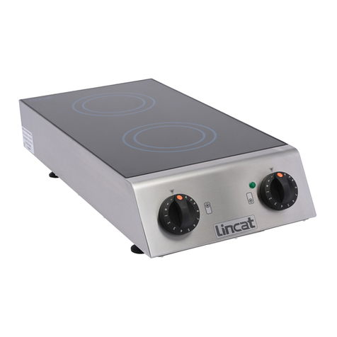
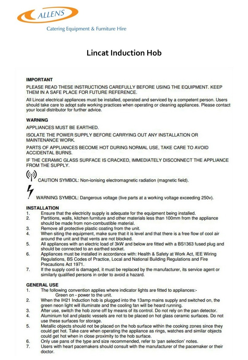
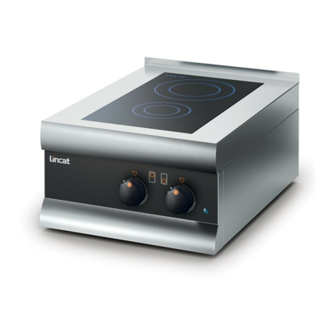
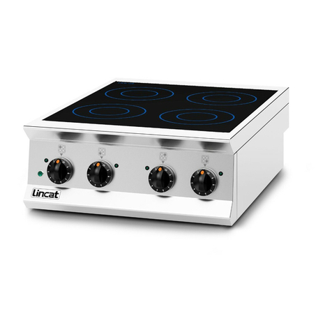
Lincat IH21 Owner's manual

IS 519 ECN 3681 Page 1 of 12
Installation, Operating and Servicing
Instructions
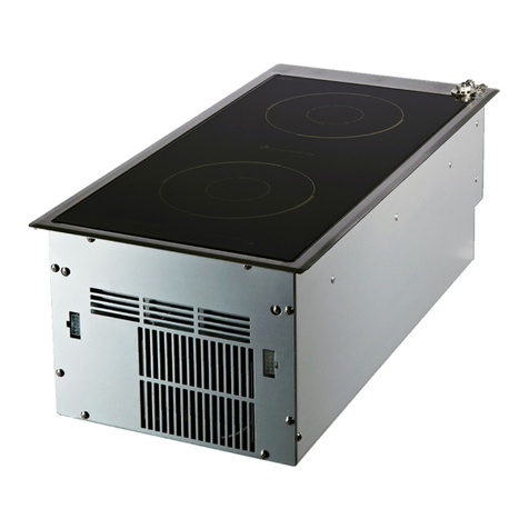
Twin Zone Induction Hob
IH21
Please make a note of your product details for
future use:
Date Purchased:_________________________
Model Number:__________________________
Serial Number:__________________________
Dealer:_________________________________
_______________________________________

IS 519 ECN 3681 Page 2 of 12
CONTENTS
Important Information
2
Warnings and Precautions
3
Technical Data
3
Checklist of Enclosures
3
Installation and Commissioning
3-5
Operating Instructions
5-9
Cleaning
9
Servicing, Maintenance and Component Replacement
10
Fault Finding
11
Spare Parts List
11
Service Information and Guarantee
12
IMPORTANT INFORMATION
Read these instructions carefully before using this product, paying particular
attention to all sections that carry warning symbols, caution symbols and notices.
Ensure that these are understood at all times.
WARNING!
This symbol is used whenever there is a risk of personal injury.
CAUTION!
This symbol is used whenever there is a risk of damaging your Lincat product.
NOTE:
This symbol is used to provide additional information, hints and tips.
KEEP THIS MANUAL FOR FUTURE REFERENCE

IS 519 ECN 3681 Page 3 of 12
WARNINGS AND PRECAUTIONS
This appliance must be installed, commissioned and serviced by a qualified person
in accordance with national and local regulations in force in the country of
installation.
If the supply cord is damaged, it must be replaced by the manufacturer, its service
agent or similarly qualified person.
Ensure that the plug/socket is accessible at all times.
Strip plastic coating and clean the appliance before use.
During operation parts may become hot - avoid accidental contact.
Disconnect this appliance before servicing, maintenance or cleaning.
Caution symbol: Non-ionising electromagnetic radiation (magnetic field)
Warning symbol: Dangerous voltage (live parts at a working voltage exceeding
250v)
TECHNICAL DATA
Model
Height (mm)
Width (mm)
Depth (mm)
Weight (kg)
IH21
115
350
654
12
CHECK LIST OF ENCLOSURES
Warranty card
Instructions manual
INSTALLATION AND COMMISSIONING
This appliance must be earthed.
If replacing the plug connect the terminals as follows:
Green and Yellow wire Earth E
Blue wire Neutral N
Brown wire Live L

IS 519 ECN 3681 Page 4 of 12
Supply cords shall be oil resistant, sheathed flexible cable not lighter than ordinary
polychloroprene or equivalent elastomer sheathed cord (code 60245 IEC 57)
Install this appliance on a level surface ensuring all vents are unobstructed. Any
partitions, walls or furniture must be of non-combustible material. Minimum
distances A 100mm B 1000mm –see Fig 1
Fig 1

IS 519 ECN 3681 Page 5 of 12
Power Ratings
Model
kW
Amps
Supply
IH21
3.0
13.0
230V/1ph/50Hz
Heat input rear zone, normal
2.0
8.7
Heat input rear zone, boost
3.0
13.0
Heat input front zone, normal
1.0
4.3
Heat input front zone, boost
1.8
7.8
Max total heat input cannot exceed 3kW
OPERATING INSTRUCTIONS
Only qualified or trained personnel should use this appliance.
Do not place metal objects, aluminium foil and plastic vessels on the ceramic
surface, and do not use the surface for storage.
Rings, watches and similar objects could get hot when in close proximity to the hob
surface.
Users with heart pacemakers should consult with the manufacturer of the
pacemaker or their doctor.
Information
With induction cooking, heat is produced directly in the base of the pan. The
system comprises a ceramic glass hob surface with an induction coil beneath,
which generates an alternating magnetic field. When a pan with a magnetic base is
placed on the cooking zone, eddy currents are created in the pan base leading to
the production of heat. The pan heats quickly. The quality of the cookware is
important to the efficiency of induction cooking. The pan base must be flat with
good heat distribution. Generally, suitable pans are made from cast iron, enamelled
steel and stainless steel with a magnetic base. Unsuitable pans are glass,
earthenware, aluminium, copper and non-magnetic stainless steel. Use pans of the
size and type recommended.
Operation of the pan detection system is dependent on the size of the pan and its
material.
Recommended pan base diameters
Rear zone
Front zone
Minimum pan
180mm
120mm
Limit of detection
135mm
90mm
Nominal coil diameter
210mm
145mm
The pan should be located concentrically over the glass target ring. If the inner ring
of the ceramic glass is visible around the pan, the pan is too small.

IS 519 ECN 3681 Page 6 of 12
It is normal for induction generators to make buzzing, whistling and clicking noises,
especially on lower power settings.
If the ceramic glass surface is cracked, immediately disconnect the appliance
from the supply.
Use
Connect to the mains supply and switch on via the On/Off switch located on the
base of the appliance (see Fig 4). The green neon will illuminate and the cooling
fan will be heard.
Control knob functions
Fig 2
A Off. B Low temperature hold. C Level 1. D Level 2. E Hob indicator. F Level 3.
G Level 4. H Level 5. I Level 6. J Level 7. K Level 8. L Level 9. M Power boost.
N Automatic heat up and control lock.
Warning: Do not move the control knob directly between Power Boost and
Automatic Heat Up.

IS 519 ECN 3681 Page 7 of 12
The following symbols are observed through the ceramic glass:
Fig 3
Low temperature hold
The pan base temperature is monitored through the hobtop, allowing dishes to be kept
warm. The ‘u’ symbol is displayed. The food type, flatness of pan base and pan
material will have a significant effect on the temperature of the pan contents, therefore
to comply with food minimum safe holding temperatures, lids should be fitted and a
temperature probe used frequently.
Low temperature hold
Power level setting (1-9)
Power boost function
Automatic heat up control
Control lock function
Pan detection (no pan present)
Residual heat display
Error codes - generator
Error –rotary control (lightning symbol)

IS 519 ECN 3681 Page 8 of 12
Power level settings
9 power level settings are available. The table gives the percentage of maximum
power for each setting with the time limit for operation at that power.
Power level
Low temp
hold
1
2
3
4
5
6
7
8
9
% of power
---
3%
5%
8%
12%
18%
28%
42%
64%
100%
Time limit
(mins)
120
520
402
318
260
212
170
139
113
90
Power boost function
Power boost is activated by turning the control clockwise from level 9. Only one coil
can be boosted at a time.
The IH21 is rated at 3kW total input, therefore:
If the rear coil (2kW) is power boosted, its power increases to 3kW and the front coil
will be shut down.
If the front coil (1kW) is power boosted, its power increases to 1.8kW and the rear coil
is limited to 1.2kW.
The power boost will run for a maximum of 10 minutes before reverting to level 9. It
may be boosted again, providing the system internal temperatures are satisfactory.
Automatic heat-up control (AHC)
When activated, the AHC will give maximum power (level 9) to a coil for a preset time
before reducing to a lower power level set by the control. To activate, the control is
turned anticlockwise from the ‘Off’ position briefly whilst the ‘A’ symbol illuminates: the
control is then turned clockwise to set the ‘final’ required power (1-8). The display
reverts to the ‘A’ symbol and the hob will run at maximum power for the time shown in
the table, before reducing power to the ‘final’ setting.
Power level setting
1
2
3
4
5
6
7
8
Preset time (secs)
40
72
120
176
256
432
120
192
Control lock function
This function prevents unwanted operation of the hob. When the control lock is active,
the ‘L’ symbol is displayed. It is activated and de-activated by turning either control
knob anticlockwise to the control lock position and held for approximately 6 seconds.
Pan detection function
This prevents the coils being turned on without a pan being present, and also turns off
the coil as soon as a pan is removed. If the pan is of the wrong material for induction
equipment, the ‘no pan present’ symbol is displayed. After use, switch off the hob via
the control and do not rely on the pan detector.

IS 519 ECN 3681 Page 9 of 12
Residual heat display
When the temperature of the hobtop exceeds 60oC after removal of a pan, the ‘H’
symbol displays, indicating a hot surface. (Refer also to the error codes section).
Whilst the residual heat display is showing, leaving the appliance connected to the
power supply allows the cooling fans to continue to operate. When the ‘H’ symbol is
extinguished, switch off the power supply.
Error codes
There are numerous ‘E’ symbol error codes identifying issues within the system which
are primarily of use when reporting a fault to the Service Department at Lincat. Some
errors can be cleared by turning the control off, or completely turning off and
unplugging the appliance before reconnecting.
The ‘lightening’ symbol reports errors due to the control knob circuit, i.e. if a control
knob is turned anticlockwise and held in excess of 30 seconds in the ‘control lock’
position, the system may assume a ‘stuck control’ and display this symbol.
A situation such as a blocked air filter, failed cooling fan or insufficient air flow to a
confined installation, may cause the generator to overheat, resulting in the ‘H’ symbol
being displayed. Replacing the air filter, cooling fan or ensuring an adequate air flow
will rectify the issue.
CLEANING
Do not use a water jet or steam cleaner, and do not immerse this appliance.
Clean all panels with warm water and mild detergent, do not use abrasive
materials. Dry with a soft cloth.
Clean the ceramic glass with a scraper or Vileda CERAN cleaning sponge –use a
few drops of a suitable cleaner on a paper towel or the rough side of the sponge.
Wipe with a damp cloth and dry with a clean cloth.
Check the air filter and replace if contaminated (see Component Replacement).
Plastic, aluminium foil or sugary food must be scraped of the ceramic glass
immediately. If these substances melt they can damage the surface.

IS 519 ECN 3681 Page 10 of 12
SERVICING, MAINTENANCE AND
COMPONENT REPLACEMENT
Replacement of air filter
Cool the appliance and disconnect from supply. Turn the hob on its back or side
without scratching the cooking surface.
Push the slide latch (Fig 4) and lift the filter cover away from the base. Replace the
used filter with a new one. Reverse the procedure to re-fit the cover. Do not
operate the appliance without a filter, as dirt and grease could be drawn into the
electronics, impairing safe operation.
Fig 4
All other servicing, maintenance and component replacement on this appliance
should be carried out by one of our recommended service engineers.
A Latch
B Cover
C Filter
D On/Off switch

IS 519 ECN 3681 Page 11 of 12
Please refer to the Service Help Desk number on the final page of this manual.
Part Number
Description
FE10
Foot
FG03
Fanguard
FI33
Filter pad
KN251
Control knob
NE43
Neon
S/R0181
Cooling fan
SW89
On/Off switch
FAULT FINDING
SPARE PARTS LIST

IS 519 ECN 3681 Page 12 of 12
For help with the installation, maintenance and use of your Lincat equipment,
please contact our service department:
UK: 01522 875520
For non-UK customers, please contact your local Lincat dealer
All service work, other than routine cleaning should be carried out by one of our
authorised service agents. We cannot accept responsibility for work carried out by
other persons.
To ensure your service enquiry is handled as efficiently as possible, please tell us:
Brief details of the problem
Product code
All available on serial plate
Type number
Serial number
Lincat reserve the right to carry out any work under warranty, given reasonable
access to the appliance, during normal working hours, Monday to Friday, 08:30 to
17:00.
GUARANTEE
This unit carries a comprehensive UK mainland 2 year warranty. The guarantee is
in addition to, and does not diminish your statutory or legal rights.
The guarantee does not cover:
Accidental damage, misuse or use not in accordance with the manufacturer’s
instructions
Consumable items (such as filters, glass, bulbs, slot toaster elements and door
seals.)
Damage due to incorrect installation, modification, unauthorised service work or
damage due to scale, food debris build-up, etc.
The manufacturer disclaims any liability for incidental, or consequential damages.
Attendance is based on reasonable access to the appliance to allow the authorised
technician to carry out the warranty work.
Service calls to equipment under warranty will be carried out in accordance with the
conditions of sale. Unless otherwise specified, a maximum of 15 minutes of
administrative time, not spent directly carrying out servicing work, is provided for
within the warranty. Any requirement for staff attending the call to spend greater time
than 15 minutes due to administrative requirements, such as on health and safety risk
assessments, will be chargeable at the prevailing rate.
SERVICE INFORMATION
Other manuals for IH21
3
Table of contents
Other Lincat Hob manuals

Lincat
Lincat PHEH01 User guide

Lincat
Lincat Opus 700 Series Operating instructions

Lincat
Lincat IH21 Operating instructions

Lincat
Lincat Opus 800 OE8013 Owner's manual

Lincat
Lincat IH21 Setup guide

Lincat
Lincat DK977 User guide

Lincat
Lincat Silverlink SLI21 Owner's manual

Lincat
Lincat IH21 Owner's manual

Lincat
Lincat OE8013 Owner's manual

Lincat
Lincat Silverlink 600 HT3 User manual