IS 565 ECN 3766 Page 10 of 13
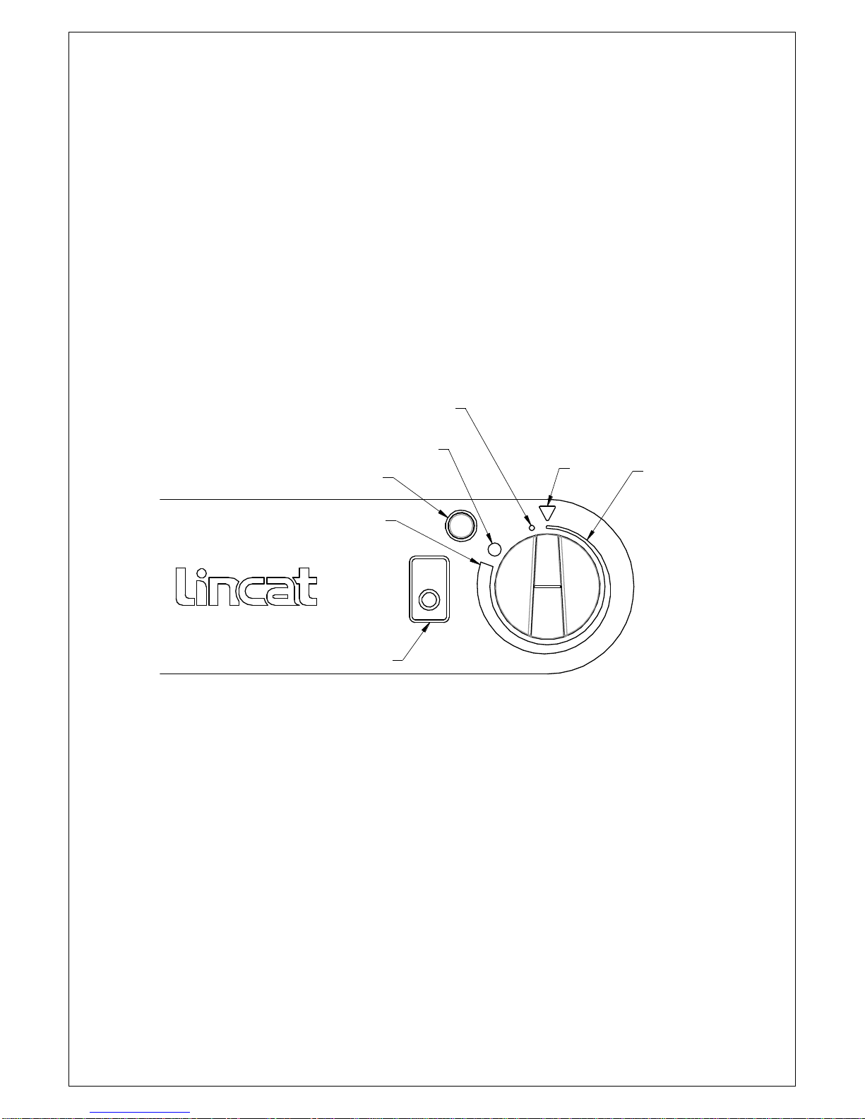
Residual heat display
When the temperature of the hobtop exceeds 60oC after removal of a pan, the ‘H’
symbol displays, indicating a hot surface, (See also the Error code section).
Leaving the appliance connected to the power supply whilst the residual heat display
is showing allows the cooling fans to continue to operate. When the ‘H’ symbol is
extinguished, the power supply can be switched off.
Error codes
There are numerous ‘E’ symbol error codes identifying issues within the system which
are primarily of use when reporting a fault to the Service Department at Lincat. Some
errors can be cleared by turning the control off, or completely turning off and
unplugging the appliance before reconnecting, or by allowing the unit to cool down.
The ‘lightning’ symbol reports errors due to the control knob circuit, i.e. if a control
knob is turned anticlockwise and held in excess of 30 seconds in the ‘control lock’
position, the system may assume a ‘stuck control’ and display this symbol.
A situation such as a blocked air filter, failed cooling fan or insufficient air flow may
cause the generator to overheat, resulting in the ‘H’ symbol being displayed.
Replacing the air filter, cooling fan or ensuring an adequate air flow will rectify the
issue.
Locating the appliance where the exhaust airflow is constrained and allowed to
recirculate back into the air inlet, will eventually cause overheating of the unit.
The ‘H’ symbol will also display if the operating time limit is exceeded, this time limit
varies with power level (see Power Level Settings).
Turning the control off and then back on, will resume operation.
Do not use a water jet or steam cleaner, and do not immerse this appliance.
Clean all panels with warm water and mild detergent, do not use abrasive
materials. Dry with a soft cloth.
Clean the ceramic glass with a scraper or Vileda CERAN cleaning sponge –use a
few drops of a suitable cleaner on a paper towel or the rough side of the sponge.
Wipe with a damp cloth and dry with a clean cloth.
Check the air filter and replace if contaminated (see Component Replacement).
Plastic, aluminium foil or sugary food must be scraped off the ceramic glass
immediately. If these substances melt they can damage the surface.