Lince GOLD 869 9551-GOLD-FOG User manual

IT
EN
NEBBIOGENO RADIO
Manuale di installazione, uso e manutenzione
Installation, operation and maintenance manual
WIRELESS FOGGING SYSTEM
ART. / ITEM:
9551-GOLD-FOG
NEBBIOGENO RADIO
WIRELESS FOGGING
SYSTEM
MADE IN ITALY
La dichiarazione CE del presente articolo
è reperibile sul sito www.lince.net.
The CE declaration of this item is available
on www.lince.net website.

2
LINCE ITALIA S.p.A.
- Istruzioni originali -
1. INTRODUZIONE
Il manuale descrive le modalità di installazione del sistema
nebbiogeno radio. Il nebbiogeno radio è adatto a proteggere
aree di piccole/medie dimensioni (case, negozi, sportelli
bancomat), collegabile via radio alle centrali della serie GOLD
869. Grazie ad un'innovativa formulazione del uido erogato,
contenente una elevata percentuale di glicole, garantisce una
nebbia densa, totalmente impenetrabile alla vista. Il perfetto
isolamento termico permette consumi molto contenuti e quindi un
risparmio di energia in confronto ad altri sistemi nebbiogeni. Un
esclusivo sistema antisabotaggio brevettato permette di rilevare
automaticamente se l’ugello è stato ostruito, inviando un segnale
in caso di manomissione. Il sistema è realizzato/progettato
secondo i vigenti standard Europei. Il liquido nebbiogeno è
testato e assolutamente sicuro (certicazione tossicologica).
Non è dannoso per persone, animali e oggetti e non lascia alcun
residuo. Nella confezione è inclusa una bombola per il montaggio
verticale.
INDICE
1. INTRODUZIONE................................................................................................ 2
1.1 CONDIZIONI DI UTILIZZO E AVVERTENZE......................................... 3
1.2 LINEE GUIDA PER L'INSTALLAZIONE ................................................. 4
1.3 CARATTERISTICHE TECNICHE........................................................... 5
1.4 CONTENUTO DELLA CONFEZIONE .................................................... 5
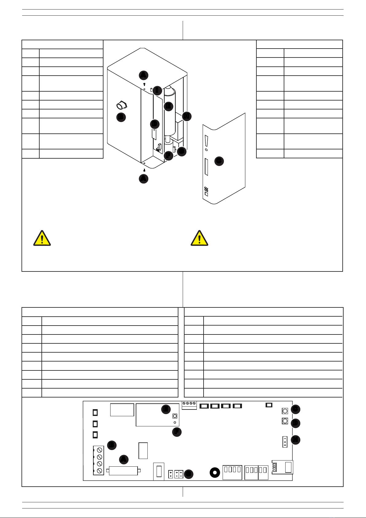
1.5 DESCRIZIONE DELLE PARTI ............................................................... 6
1.6 DESCRIZIONE DELLA SCHEDA........................................................... 6
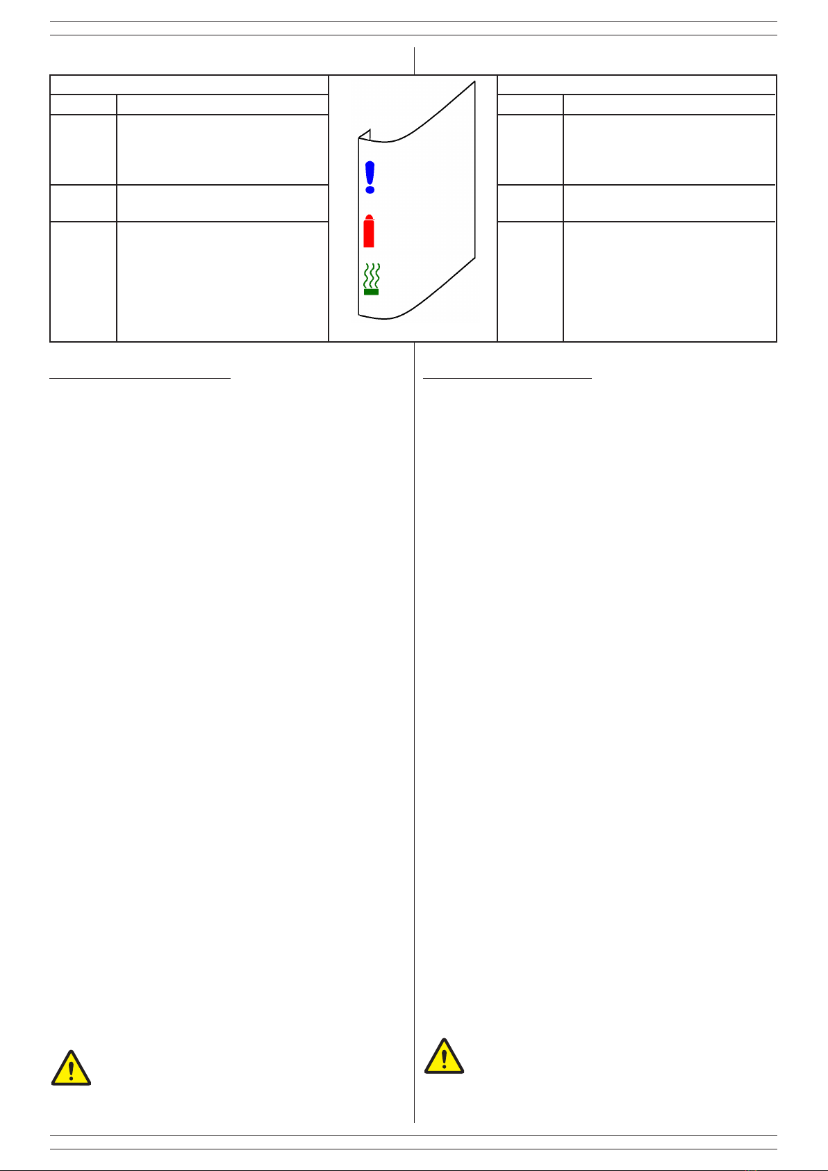
1.7 SIGNIFICATO DELLE SPIE FRONTALI................................................. 7
2. INSTALLAZIONE............................................................................................... 7
2.1 MONTAGGIO A MURO .......................................................................... 7
2.2 INSTALLAZIONE E SOSTITUZIONE DELLE BOMBOLE...................... 7
2.3 DIREZIONE DEL FLUSSO DI NEBBIA.................................................. 8
2.4 COLLEGAMENTO ALL'ALIMENTAZIONE DI RETE.............................. 8
2.5 ALIMENTAZIONE A PILE....................................................................... 9
3. MEMORIZZAZIONE E CONFIGURAZIONE PARAMETRI............................... 9
3.1 FUNZIONE SLEEP................................................................................. 9
4. MANUTENZIONE E VERIFICHE PERIODICHE ............................................. 10
4.1 SALITA/DISCESA MARTINETTI - VERIFICA DI SCORRIMENTO ...... 10
4.2 VERIFICA DELLA TENUTA PNEUMATICA DEL CIRCUITO E DEL
PRESSOSTATO .............................................................................................. 10
4.3 VERIFICA PILE E PORTAPILE............................................................ 11
4.4 RIPRISTINO DA SEGNALAZIONI DI GUASTO................................... 11
5. DIFETTI E POSSIBILI SOLUZIONI................................................................. 12
6. SMALTIMENTO E ROTTAMAZIONE.............................................................. 13
7. TABELLA ASSISTENZA ................................................................................. 14
1. DESCRITPION .................................................................................................. 2
1.1 CONDITIONS OF USE AND WARNINGS ............................................. 3
1.2 GUIDELINES FOR INSTALLATION....................................................... 4
1.3 TECHNICAL FEATURES ....................................................................... 5
1.4 PACKAGING CONTENTS...................................................................... 5
1.5 PARTS DESCRIPTION .......................................................................... 6
1.6 BOARD DESCRIPTION ......................................................................... 6
1.7 MEANING OF THE FRONT LIGHTS ..................................................... 7
2. INSTALLATION ................................................................................................. 7
2.1 WALL MOUNTING ................................................................................. 7
2.2 INSTALLATION AND REPLACEMENT OF THE BOTTLES................... 7
2.3 DIRECTION OF THE FOG FLOW ......................................................... 8
2.4 CONNECTION TO THE MAINS............................................................. 8
2.5 BATTERY POWER SUPPLY.................................................................. 9
3. STORING AND SETTINGS ............................................................................... 9
3.1 SLEEP FUNCTION ................................................................................ 9
4. PERIODIC MAINTENANCE AND CHECKS ................................................... 10
4.1 UP/DOWN JACKS - SLIDING CHECK ................................................ 10
4.2 CHECKING THE PNEUMATIC SEAL OF THE CIRCUIT AND THE
PRESSURE SWITCH...................................................................................... 10
4.3 BATTERIES AND BATERREIS CASE CHECKING ............................. 11
4.4 RECOVERY FROM FAILURE SIGNALS ............................................. 11
5. TROUBLESHOOTING .................................................................................... 12
6. DISPOSAL AND SCRAPPING........................................................................ 13
7. ASSISTANCE TABLE ..................................................................................... 14
- Translation of the original instructions (original instructions in Italian) -
CONTENTS
1. DESCRIPTION
The manual describes how to install the wireless fogging system.
It is ideal to protect small/medium areas like shops, homes, bank
ATM machines. It can be wireless connected to all GOLD 869
series control panels. Thanks to an innovative formulation of the
uid with a high percentage of glycol, it ensures a dense fog
which is totally impenetrable to the visibility. The perfect insulation
system provides very low power consumption that allows you
to save costs in comparison with other fogging systems. An
exclusive anti-tamper system allows to detect automatically
if the nozzle is tampered and to send an advise signal. The
system is designed and manufactured according to the current
European standards. The fog uid is tested and absolutely safe
(toxicological certication). They are not dangerous for objects,
animals, people and does not leave residuals. The package
includes a bottle for vertical mounting.
Le informazioni riportate in questo manuale sono state compilate con
cura, tuttavia LINCE ITALIA S.p.A. non può essere ritenuta responsabile
per eventuali errori e/o omissioni. LINCE ITALIA S.p.A. si riserva il diritto
di apportare in ogni momento e senza preavviso, miglioramenti e/o
modiche ai prodotti descritti nel presente manuale. Consultare il sito
www.lince.net per le condizioni di assistenza e garanzia. LINCE ITALIA
S.p.A. pone particolare attenzione al rispetto dell’ambiente. Tutti i prodotti
ed i processi produttivi sono progettati con criteri di eco-compatibilità.
Il presente articolo è stato prodotto in Italia.
• L’azienda ha un sistema di gestione della qualità certicato
secondo la norma ISO 9001: 2008 (n° 4796 - A)
• L’azienda ha un sistema di gestione ambientale certicato
secondo la norma ISO 14001: 2004 (n° 4796 - E)
• L’azienda ha un sistema di gestione della salute e sicurezza sul
lavoro OHSAS 18001: 2007 (n° 4796 - I)
The information in this manual has been issued with care, but LINCE
ITALIA S.p.A. will not be responsible for any errors or omissions. LINCE
ITALIA S.p.A. reserves the right to improve or modify the products
described in this manual at any time and without advance notice.Terms
and conditions regarding assistance and the product warranty can be
found at LINCE ITALIA’s website www.lince.net. LINCE ITALIA S.p.A.
makes it a priority to respect the environment. All products and production
processes are designed to be eco-friendly and sustainable.
This product has been Made in Italy.
• The company has a certied system of quality management
according to ISO 9001: 2008 (n° 4796 - A) standard.
• The company has a certied system of environmental
management according to ISO 9001: 2004 (n° 4796 - E) standard.
• The company has a certied system of health and work
security management according to OHSAS 18001: 2007 (n°
4796 - I) standard.

3
LINCE ITALIA S.p.A.
1.1 CONDIZIONI DI UTILIZZO E AVVERTENZE
La nebbia generata dal dispositivo non crea disturbi o danni alle
persone durante una permanenza non prolungata in una stanza
satura di nebbia e se il sistema è utilizzato nel rispetto delle
raccomandazioni del fabbricante. La nebbia prodotta è certicata
in conformità alle norme Europee e il dispositivo è conforme
per certicazioni ed emissioni elettromagnetiche a quanto
stabilito dalle autorità Europee. Eventuali certicazioni richieste
in un Paese specico sono responsabilità del distributore di tale
Paese. I documenti relativi alle certicazioni possono essere
richiesti tramite email dall’acquirente del prodotto a: info@lince.
net. Il produttore declina ogni responsabilità in caso di utilizzo
del dispositivo in presenza di oggetti che possano subire danni
di qualunque genere a contatto con sostanze contenenti glicole,
acqua ed alcool. Il personale che possa essere esposto alla
nebbia emessa dal dispositivo, deve essere preventivamente
avvisato e deve essere vericato che non abbia allergie
speciche alle summenzionate sostanze. Alla data di redazione
del presente manuale non è mai stato rilevato alcun problema
derivante da allergia. Lince Italia S. p. A. non si riterrà in ogni
caso responsabile per ogni danno o particolare situazione d’uso
che non sia stata preventivamente sottoposta alla sua attenzione
tramite comunicazione scritta, ed espressamente approvata per
scritto, prima dell’installazione dei suoi prodotti. Relativamente
al liquido nebbiogeno cortesemente si consulti attentamente il
documento sulla sicurezza del liquido nebbiogeno pubblicato sul
sito web www.lince.net . In ogni caso consultare immediatamente
un medico nel caso di ingestione del liquido o se dopo il contatto
del medesimo con gli occhi o con la pelle si presenti qualunque
tipo di reazione. Nel caso, ad ogni modo, lavare immediatamente
la parte esposta con acqua. Non sostare mai a lungo in un locale
saturo di nebbia. Non utilizzare bombole di ricarica che non siano
quelle originali distribuite da Lince Italia S. p. A. e non cercare mai
di ricaricarle, sono bombole monouso. Rispettare le normative
in vigore per lo smaltimento delle bombole vuote. Conservare
le bombole lontano dalla portata di bambini e animali. L’ugello
di emissione nebbia del dispositivo può raggiungere alte
temperature e il contatto con il medesimo può causare ustioni.
Non guardare direttamente nel foro dell’ugello di emissione.
Non utilizzare mai Il dispositivo per qualunque uso che non
sia correlato alla protezione da furto o rapina (la scelta della
modalità di utilizzo in caso di rapina viene demandata al vostro
consulente per la sicurezza). Non usare mai liquidi nebbiogeni
differenti da quelli forniti da Lince Italia S.p.A. e non aggiungere
alcuna altra sostanza all’interno delle bombole. Non utilizzare o
tenere in carica il dispositivo in alcun genere di veicolo e non
trasportare il dispositivo se non sono trascorse almeno 24 ore dal
suo spegnimento. Durante il trasporto il dispositivo deve essere
disattivato.
1.1 CONDITIONS OF USE AND WARNINGS
The fog generated by the device does not create disturbances
or damage to people during a non-prolonged stay in a room
saturated with fog and if the system is used in compliance with the
manufacturer's recommendations. The fog produced is certied in
compliance with European standards and the device is compliant
with certications and electromagnetic emissions as established
by the European authorities. The local distributor is responsible
for eventual certications requested in a specic country. The
documents relating to the certications can be requested by
manufacturer declines all responsibilities in case of use of the
device in the presence of objects that can suffer damage of any
kind in contact with substances containing glycol, water and
alcohol. Personnel who may be exposed to the fog emitted by
the device must be notied in advance and must be veried
that they do not have specic allergies to the above-mentioned
substances. At the date of writing of this manual no problem
arising from allergy has ever been detected. Lince Italia S. p. A.
will not be responsible in any case for any damage or particular
situation of use that has not been previously submitted to its
attention through written communication, and expressly approved
in writing, before the installation of its products. Concerning the
foggy liquid, please consult the foggy liquid safety document
published on the website www.lince.net. In any case, immediately
consult a doctor in case of ingestion of the liquid or if after contact
with eyes or skin, any type of reaction is present. In any case,
immediately wash the exposed part with water. Never stand for a
long time in a room full of fog. Do not use rell Bottles other than
the original ones distributed by Lince Italia S. p. A. and never
try to recharge them, they are single-use Bottles. Comply with
the regulations in force for the disposal of empty Bottles. Keep
the Bottles away from children and animals. The fog emission
nozzle of the device can reach high temperatures and contact
with it can cause burns. Do not look directly into the hole of the
emission nozzle. Never use the device for any use that is not
related to theft protection or robbery (the choice of how to use in
case of robbery is referred to your security consultant). Never use
misty liquids different from those supplied by Lince Italia S.p.A.
and do not add any other substance inside the Bottles. Do not
use or keep the device in any kind of vehicle and do not carry the
device if at least 24 hours have elapsed since it was turned off.
The device must be deactivated during transport.

4
LINCE ITALIA S.p.A.
1.2 LINEE GUIDA PER L'INSTALLAZIONE
Si raccomanda cortesemente di osservare le seguenti indicazioni
nel montaggio del dispositivo:
• L’apparecchio deve essere installato in modo da non
intralciare o bloccare le vie di fuga dal locale;
• vericare che la nebbia non tolga la visibilità in prossimità
di: scale, pianerottoli, dislivelli, organi in movimento o altro
che possano causare: cadute, ferimenti o danni di qualsiasi
genere alle persone;
• non guardare direttamente nel foro dell’ugello di emissione.
non aggiungere alcuna altra sostanza all’interno delle
bombole.
• l’ugello di emissione nebbia del dispositivo può raggiungere
alte temperature e il contatto con il medesimo può causare
ustioni per cui quando il dispositivo è pronto all’uso (LED
blu accesi) evitare di sostare a meno di 50 cm dall’ugello
diffusore. Si raccomanda inoltre di rimanere a non meno di
1 metro di distanza quando il dispositivo emette il getto di
nebbia;
• quando si effettuano prove di funzionamento del dispositivo
si ricorda di avvisare preventivamente i Vigili del Fuoco della
zona onde prevenire falsi allarmi;
• si ricorda di applicare le apposite vetrofanie in dotazione
segnalanti la presenza del dispositivo alle vetrine ed alle
nestre dei locali interessati;
• si consiglia di segnalare l’installazione del dispositivo alla
sede dei Vigili del Fuoco competente per la vostra zona e se
necessario anche alle eventuali altre istituzioni di controllo
del territorio presenti nell’area;
• non dirigere mai il getto del nebbiogeno direttamente contro
oggetti o pareti posti a meno di 2 metri dallo stesso, se
possibile mantenere una distanza maggiore. A causa della
sua potenza il getto di nebbia del dispositivo, durante i primi
3 secondi di erogazione può superare i 10 metri di distanza
dal punto in cui è installato;
• denire il tempo di sparo nel rispetto dei tempi minimi e
massimi deniti nell’apposita tabella dei tempi che viene
riportata in seguito, evitando eccessi. Anche se la nebbia
prodotta è asciutta e generalmente non lascia residui, uno
sparo troppo prolungato rispetto ai tempi consigliati potrebbe
generare residui nell’ambiente;
• il dispositivo può rimanere attivo oltre 2 ore in mancanza
dell’alimentazione a 230 Vca grazie al suo isolamento
termico che mantiene a lungo le temperature nello
scambiatore di calore;
• installare preferibilmente il dispositivo ad un’altezza
minima di circa 2,5 metri, al ne di limitare la possibilità di
manomissione;
• installare il dispositivo con un’inclinazione massima di 20°;
• non spostare o muovere il dispositivo quando è ancora
caldo;
• l’unità principale del dispositivo, che comprende il sistema
di riscaldamento rinchiuso nel contenitore metallico, non
deve essere aperta se non da centri di assistenza qualicati
ed autorizzati. L’unità non deve in ogni caso essere aperta
per nessun motivo, e l’isolamento non deve essere toccato,
prima che siano trascorse almeno 24 ore da quando
il dispositivo è stato spento. Le parti interne possono
raggiungere temperature molto elevate;
• non attivare il dispositivo prima che l’installazione sia
completata;
• inserire le bombole come ultima operazione e vericare la
funzione di antimanomissione;
1.2 GUIDELINES FOR INSTALLATION
Please observe the following instructions when installing the
device:
• The device must be installed so as not to hinder or block the
escape routes from the room;
• check that the fog does not remove the visibility near: stairs,
landings, gradients, moving parts or anything else that can
cause: falls, injuries or damages of any kind to people;
• do not look directly into the hole of the emission nozzle. do
not add any other substance inside the Bottles.
• the fog emission nozzle of the device can reach high
temperatures and contact with it can cause burns, so
when the device is ready for use (blue LEDs on) avoid
stopping less than 50 cm from the diffuser nozzle. It is also
recommended that you stay at least 1 meter away when the
device emits a jet of mist;
• when testing the device, please remember to notify the local
Fire Department in advance in order to prevent false alarms;
• remember to apply the appropriate window stickers provided
indicating the presence of the device to the windows of the
affected rooms;
• it is advisable to report the installation of the device to the
competent Fire Department for your area and if necessary
also to any other local control institutions in the area;
• never direct the mist spray directly against objects or walls
placed less than 2 meters from it, if possible keep a greater
distance. Because of its power, the fog jet of the device,
during the rst 3 seconds of delivery can exceed 10 meters
away from where it is installed;
• dene the ring time in compliance with the minimum and
maximum times dened in the appropriate time table which
is shown below, avoiding excesses. Even if the fog produced
is dry and generally does not leave residues, a shot that is
too prolonged compared to the recommended times could
generate residues in the environment;
• the device may remain active for more than 2 hours if the
230 Vac power supply is not available due to its thermal
insulation which keeps the temperatures in the heat
exchanger for a long time;
• preferably install the device at a minimum height of about
2.5 meters, in order to limit the possibility of tampering;
• install the device with a maximum inclination of 20°;
• do not move the device when it is still hot;
• the main unit of the device, which includes the heating
system enclosed in the metal container, must not be opened
except by qualied and authorized service centers. The unit
must not in any case be opened for any reason, and the
insulation must not be touched, before at least 24 hours
have elapsed since the device has been turned off. The
internal parts can reach very high temperatures;
• do not activate the device before installation is complete;
• insert the Bottles as a last operation and check the anti-
tampering function;

5
LINCE ITALIA S.p.A.
• effettuare sempre una prova del sistema ad installazione
terminata;
• si ricorda che dal momento dell’accensione a freddo del
dispositivo occorre almeno un’ora perché venga raggiunta
la temperatura minima occorrente per lo sparo del getto di
nebbia;
• evitare di installare il dispositivo di fronte ad ostacoli che
possano provocare la deviazione del getto di nebbia;
• la temperatura esterna del dispositivo può variare fra la
temperatura ambiente e 50 gradi centigradi;
• richiedete alla Lince Italia S.p.A. od ai suoi distributori di
prendere parte ai corsi per installatori per assicurare la
migliore installazione del dispositivo;
1.3 CARATTERISTICHE TECNICHE
9551-GOLD-FOG
Alimentazione 230 Vca
Consumo medio in
mantenimento 37 W
Consumo medio in
riscaldamento 270 W
Potenza massima resistenza 300 W
Assorbimento @12 V 500 mA durante lo sparo
60 mA a riposo
Autonomia in assenza di
alimentazione ~2 h
Tempo di riscaldamento ~70 min
Autonomia termica 2,5 h
Massima nebbia per ogni
singola erogazione
visibilità 1,5 m: no a 300 m3
visibilità nulla: no a 200 m3
Tempo max di erogazione 25 s
Capacità max di erogazione 600 m3
Capacità bombola 1 x 400 ml
Pile di backup 6 pile non ricaricabili AA
(non incluse)
Frequenza di esercizio 869,40 ÷ 869,65 MHz 1 canale
868,00 ÷ 868,60 MHz 4 canali
Sicurezza della trasmissione FH; TDMA; AES
Portata radio no a 1.500 m in aria libera
Dimensioni 26,5 x 19,0 x 345 mm
Peso della confezione 10 kg (senza bombole o pile)
• always carry out a test of the system after installation;
• remember that from the moment of cold start of the device
it takes at least an hour to reach the minimum temperature
required for the ring of the fog jet;
• eavoid installing the device in front of obstacles that may
cause the jet of fog to deviate;
• the external temperature of the device may vary between
room temperature and 50 degrees centigrade;
• ask to Lince Italia S.p.A. or its distributors to take part in
installer courses to ensure the best installation of the device;
1.2 TECHNICAL FEATURES
9551-GOLD-FOG
Operating voltage 230 Vac
Average power consumption
in maintenance 37 W
Average power consumption
in heating 270 W
Max resistance power 300 W
Absorption @ 12 V 500 mA in shooting
60 mA in stand-by
Working time without mains
power ~2 h
Heat up time ~70 min
Thermal autonomy 2,5 h
Max fog single shot visibility 1,5m: up to 300 m3
no visibility: up to 200 m3
Max shooting time 25 s
Max fog emission 600 m3
Bottle capacity 1 x 400 ml
Backup battery 6 AA not rechargable batteries (non
incluse)
Operating frequency 869,40 ÷ 869,65 MHz 1 channel
868,00 ÷ 868,60 MHz 4 channels
Security transmission FH; TDMA; AES
Wireless range up to 1,500 m in free air
Dimensions 26.5 x 19.0 x 34.5 mm
Package weight 10 kg (without Bottle or batteries)
1.4 CONTENUTO DELLA CONFEZIONE
Tabella 1
Part. Identicazione
ANebbiogeno
BManuale di istruzioni
CCartello dissuasore
adesivo
DAntenna
A
B
1.3 PACKAGING CONTENTS
Fig. 2
Table 1
Ref. Identication
AFogging system
BIstruction manual
CAdhesive bollard sign
DAntenna
C
D

6
LINCE ITALIA S.p.A.
1.5 DESCRIZIONE DELLE PARTI
Tabella 1
Part. Identicazione
AViti chiusura coperchio
BUgello
CCoperchio con LED di
stato
DScheda madre
EBombola
FMartinetto
GPacco batterie di ba-
ckup (non fornite)
HAlimentatore 12 Vcc
(già cablato)
IConnettore antenna
1.5 PARTS DESCRIPTION
Table 1
Ref. Identication
ACover closure screws
BNozzle
CCover with status
LED
DMother board
EBottle
FJack
GBackup battery pack
(not supplied)
H12 Vdc power supply
(already wired)
IAntenna connector
1.6 DESCRIZIONE DELLA SCHEDA
Tabella 2
Part. Identicazione
AFusibile
BMorsettiera di alimentazione
CTasto reset bombola
DMicroswitch antisabotaggio
ETasto di memorizzazione
FLED di stato
GJumper di servizio
HJumper verica martinetto
A
1.6 BOARD DESCRIPTION
Table 2
Ref. Identication
AFuse
BMains terminal block
CBottle rest button
DAnti-tamper microswitch
EStoring button
FStatus LED
GService Jumper
HJumper for jack checking
Fig. 3
1
2
3
4
5
6
7
8
9
FUSE
4
3
2
1
B
C
D
E
F
Fig. 4
G
H
Quando si chiude il portello, il buzzer emette un
suono per confermare la chiusura del tamper.
N.B. Prima di aprire il portello laterale vericare che la
centrale sia in servizio, in modo che l’apertura del circuito anti-
sabotaggio non causi un allarme.
B
C
D
E
A
A
G
H
F
I
When the door is closed, the buzzer emits a sound to
conrm the closure of the tamper.
N.B. Before opening the side door check that the control panel
is in service, so that the opening of the anti-tamper circuit does
not cause an alarm.

7
LINCE ITALIA S.p.A.
1.7 SIGNIFICATO DELLE SPIE FRONTALI
Tabella 3
Spia Descrizione
Blu
Acceso sso signica che è arma-
to, se caldo, è pronto a sparare.
Acceso lampeggiante indica che è
in corso una anomalia o guasto.
Rosso Acceso sso quando la bombola è
in riserva
Verde
Acceso sso signica che il dispo-
sitivo è caldo e pronto ad emettere
la nebbia
Acceso lampeggiante signica che
è in corso il riscaldamento,
il dispositivo in questa fase è fred-
do, non può sparare.
2.2 INSTALLAZIONE E SOSTITUZIONE DELLE
BOMBOLE
Le bombole sono garantite no alla data stampata nella parte
superiore della stessa. Le bombole scadute vanno sostitute an-
che se non sono ancora state utilizzate/esaurite; consigliamo la
riconsegna delle stesse al proprio rivenditore, che si occuperà
dello smaltimento/recupero. La segnalazione di “riserva” avviene
quando la macchina ha sparato per almeno il 50% della durata
presunta della bombola, non viene effettuato nessun controllo
sulla effettiva emissione di nebbia. Per questo motivo si racco-
manda di utilizzare solo bombole nuove, ed eseguire il reset
bombola solo quando effettivamente viene inserita una bombola
nuova. Dopo aver rimosso le viti del portello, è sufciente estrar-
re le bombole e resettare la spia di avviso di bombola vuota (C
g. 4-C). Compiuta questa operazione inserire la nuova bombo-
la no a che non si sente il “click” del supporto plastico alla sua
sommità che entra nell’alloggiamento, chiudere inne il portello
bombola. Qualora la bombola sembrasse “incastrata” nella parte
superiore NON tirate con forza, fate una pressione con due dita
sulla parte superiore della bombola, come per abbassarla. Do-
podiché riprovare ad estrarla. Se la bombola non entra, verica-
re se un martinetto del motore è rimasto sollevato.
E’ necessario togliere la bombola per rimuovere i fermi
(quadrotti di spugna) inseriti nel corpo valvola sopra alla
bombola, servono solo ad impedire la fuoriuscita acci-
dentale di liquido durante il trasporto. E’ necessario inserire la
bombola con l’apposito tappo nero.
2. INSTALLAZIONE
2.1 MONTAGGIO A MURO
Per l'installazione a muro procedere nel modo seguente:
• Rimuovere il coperchio svitando le 2 viti di chiusura;
• praticare quattro fori nel muro in corrispondenza dei quattro
pretagli presenti sul retro del prodotto;
• inserire nei fori praticati quattro tasselli con viti;
• rompere i pretagli;
• appendere il dispositivo in corrispondenza dei quattro fori
praticati;
• effettuare i collegamenti elettrici e le impostazioni iniziali;
• chiudere nuovamente il coperchio;
• avvitare l'antenna sul relativo connettore presente nella
parte superiore
In caso di montaggio a softto, è opportuno utilizzare la
staffa 1931-FOG-ST (ssando la staffa stessa al muro ed
agganciandovi il nebbiogeno) e la bombola 001500/00251BA da
acquistare separatamente).
2. INSTALLATION
2.1 WALL MOUNTING
For wall mounting, proceed as following:
• Remove the lid loosing the 2 screws;
• make four holes in the wall in correspondence with the four
cut-outs on the back of the product;
• insert four bolts with screws into the holes;
• break the cut-outs;
• hang the device at the four holes drilled;
• make the electrical connections and initial settings;
• connect the antenna on its connector placed on the upper
part of the device;
• close the lid again.
In case of ceiling mounting, it is advisable to use the 1931-FOG-
ST bracket (xing the bracket to the wall and hooking the
fog lamp) and the 001500/00251BA bottle (to be purchased
separately)
Table 3
Light Description
Blue
Fixed on means that it is armed, if
hot, it is ready to shoot.
Flashing indicates that an anomaly
or fault is in progress.
Red Fixed on when the tank is in reser-
ve
Green
Fixed on means that the device is
warm and ready to emit the fog
Flashing means that heating is in
progress, the device in this phase is
cold, it can not shoot.
2.2 INSTALLATION AND REPLACEMENT OF
BOTTLES
The Bottles are guaranteed until the date printed in the upper part
of the same. Expired Bottles must be replaced even if they have
not yet been used/exhausted; we recommend returning these to
your dealer, who will take care of disposal/recovery. The "reser-
ve" signal occurs when the machine has red for at least 50% of
the presumed duration of the tank, no control is carried out on
the actual emission of fog. For this reason it is recommended to
use only new bottles, and perform the bottle reset only when a
new bottle is actually inserted. After removing the door screws,
simply remove the Bottles and reset the empty Bottle warning
light (Fig. 4-C). Once this operation has been completed, insert
the new Bottle until the "click" of the top of the plastic support
entering the housing and nally close the bottle door. If the bottle
appears to be "stuck" in the upper part DO NOT pull hard, press
it with two ngers on the top of the bottle, as if to lower it. Then
try again to pull it out or to remove it. If the Bottle does not enter,
check to see if an engine jack has been raised.
It is necessary to pull out the Bottle to remove the stops
(sponge squares) inserted in the valve body above the
Bottle, they only serve to prevent the accidental leakage of liquid
during transport. It is necessary to insert the bottle with the spe-
cial black cap.
1.7 MEANING OF THE FRONT LIGHT

8
LINCE ITALIA S.p.A.
NOTE:
• La corrente di picco da considerare per il dimensionamento
dell’impianto è di 4 A;
• il collegamento alla rete elettrica 230 Vca deve essere
eseguito da un tecnico qualicato;
• collegare l’apparecchiatura alla rete elettrica solo dopo aver
terminato l’installazione;
• è tassativo collegare il morsetto di terra;
• l’apparecchio deve essere collegato alla rete elettrica tramite
un dispositivo di sezionamento che deve interrompere
entrambi i poli e deve essere di tipo magnetotermico e
differenziale per proteggere l’impianto da guasti verso terra;
• non utilizzare inverter o gruppi di continuità se non si ha la
certezza che gli stessi generino una onda sinusoidale vera,
non ricostruita.
NOTES:
• The peak current to be considered for the size of the system
is 4 A;
• the connection to the 230 Vac mains must be carried out by
a qualied technician;
• connect teh device to the electrical mains only after
completingthe installation;
• it is mandatory to connect the earth terminal;
• the device must be connected to the electrical mains by
means of a magnetothermic and differential sectioning
device which must interrput both poles to protect the system
against ground faults;
• do not use inverters or uninterruptible power supply units if
you are not sure that they generate a true, non-reconstructed
sine wave.
SI RICORDA CHE, COME TUTTE LE APPARECCHIATURE
ALIMENTATE DALLA RETE ELETTRICA 230V CHE
NECESSITANO INSTALLAZIONE, E’ SOGGETTA AL
RISPETTO DELLE NORME (D.M. 37 del 22 gennaio 2008)
Per sezione e tipologia dei conduttori, protezioni, idoneità dei
materiali ai luoghi di installazione ecc.
2.4 COLLEGAMENTO ALL'ALIMENTAZIONE DI
RETE
L’elemento riscaldante sia da 0,3 kW, l’assorbimento medio
sulla rete è di 250 W in riscaldamento e tra i 40 W e i 60 W in
mantenimento.
Per il collegamento dei morsetti (B g - 4) fare riferimento alla
tabella successiva
Tabella 4
Morsetto Descrizione
1Fase alimentazione 230 Vca
2Neutro alimentazione 230 Vca
3Connessione di terra
4Connessione di terra con coperchio metallico
ATTENZIONE !! Dopo l’emissione di nebbia, e per
alcuni minuti la ghiera dell’ugello orientabile ha temperature
elevate RISCHIO DI USTIONI SE TOCCATA a mani nude.
2.3 DIREZIONE DEL FLUSSO DI
NEBBIA
Per la corretta regolazione del usso di nebbia,
occorre allentare la ghiera metallica di ssaggio
e direzionare opportunamente l'ugello in teon
inserendo un perno metallico non appuntito del
diametro del foro senza forzare (ad esempio
una chiave a brugola). Ciò consente di vede-
re chiaramente la direzione e di mantenerla
mentre si stringe nuovamente la ghiera. Per
svitare e avvitare la ghiera dell’ugello utilizzare
una pinza in buono stato per non danneggiare
la cromatura. Non serrare eccessivamente la
ghiera, è sufciente che l’ugello in teon non
si muova. Fig. 5
2.3 DIRECTION OF THE FOG FLOW
For the correct regulation of the fog ow, loosen
the metal xing ring and conveniently direct the
teon nozzle inserting a non-pointed metal pin
with the same diameter of the hole without for-
cing (for example an Allen wrench). This allows
you to clearly see the direction and to keep it
while the ring is tightened again. To unscrew
and tighten the nozzle ring nut, use a pincer in
good condition to avoid damaging the chrome
plating. Do not over tighten the ring nut, it is
sufcient that the teon nozzle does not move.
CAUTION!! After fogemission of fog, and for some
minutes the nozzle ring nut reaches temperatures. RISK OF
BURNS IF TOUCHED with bare hands.
2.4 CONNECTION TO THE MAINS
Although the heating element is 0.3 kW, the average absorption
on the network is 250 W in heating and between 40 W and 6 0W
in maintenance.
For the connection of the terminal blocks (B g - 4), refer to the
following table
Table 4
Block Description
1Phase mains 230 Vac
2Neutral mains 230 Vac
3Ground mains connection
4Ground connection for the metallic lid

9
LINCE ITALIA S.p.A.
NOTA:
Se si desidera riportare la periferica alle impostazioni di fabbrica
premere 10 volte il microswitch di memorizzazione.
NOTE:
If you want to return the device to the factory settings, press the
storage microswitch for 10 times.
2.5 ALIMENTAZIONE A PILE
Le pile hanno lo scopo di mantenere in efcienza la scheda elet-
tronica, consentendo l’emissione della nebbia anche in assenza
di alimentazione da rete elettrica, no a quando lo scambiatore
ha una temperatura sufciente.
Le pile hanno anche lo scopo di azionare i motori che aprono la
valvola delle bombole, anche in presenza di alimentazione da
rete elettrica.
Senza le pile, con pile scariche, ricaricabili o di cattiva qualità i
motori non aprono le valvole delle bombole
Per questo motivo è fondamentale:
• utilizzare solo pile alcaline di ottima qualità di formato AA
stilo 1,5 V;
• sostituirle entro la data di scadenza;
• sostituirle entro un anno dalla messa in servizio;
• sostituirle quando il dispositivo ne segnala l’esaurimento;
• effettuare il collaudo del porta pile ad ogni intervento.
Quando si effettua l’inserimento delle pile, è indispensabile ve-
ricare che le stesse abbiano un buon contatto con il porta pile
per non pregiudicare il buon funzionamento. La modalità di ese-
cuzione del test è descritta successivamente.
3. MEMORIZZAZIONE E
CONFIGURAZIONE PARAMETRI
Per la programmazione seguire i passi riportati di seguito:
1. impostare la centrale GOLD 869 o il modulo TX/RX GOLD
869 in apprendimento periferiche facendo riferimento al
relativo manuale;
2. collegare l'alimentazione di rete; il LED sulla scheda
comincia a lampeggiare
3. entro i 30 s di stand-by premere tre volte il tastino per avviare
la fase di memorizzazione;
4. in caso di avvenuta memorizzazione il nebbiogeno spegne il
LED rosso e si pone in stand-bye
3. STORING AND SETTINGS
To program the fogging system, follow the steps reported below:
1. set the GOLD 869 control panel or the GOLD 869 transceiver
in storing mode referring to the product manual;
2. connect the mains; the red LED starts to ash;
3. Within the 30 seconds of stand-by status press for three
times the microswitch to start the storing procedure;
4. if the storing takes place, the device shut off the red LED
and enters in stand-by mode.
Le cause della mancata memorizzazione possono essere le
seguenti
• Memorizzazione non effettuata causa comunicazione
radio; in questo caso il dispositivo va in deep-sleep
da cui si esce togliendo e rimettendo la batteria e
l'alimentazione di rete;
• Memorizzazione non effettuata causa dispositivo già
memorizzato;
• Il nebbiogeno si riavvia tenendo premuto a lungo il
pulsante di memorizzazione.
2.5 BATTERY POWER SUPPLY
The batteries are designed to keep the electronic board in ef-
cient, allowing the emission of fog even when there is no power
supply, until the heat exchanger has a adeguate temperature.
The batteries also have the purpose of operating the motors that
open the bottle valve, even in the presence of power supply from
the mains.
Without batteries, with low batteries, rechargeable or poor quali-
ty, the engines do not open the Bottle valves.
For this reason it is essential:
• use only high quality alkaline 1.5 V AA size batteries;
• replace them by the expiry date;
• replace them within one year of commissioning;
• replace them when the device signals depletion;
• carry out the testing of the battery holder at each interven-
tion.
When inserting the batteries, it is essential to check that they
have a good contact with the battery holder not to compromize
appropriate functioning. The mode of execution of the test is de-
scribed below.
Lack of storage may be due to:
• to lack of wireless communication; in this case the
device goes in deep-sleep mode from which it comes
out by removing and replacing the battery and the
mains;
• storing already performed;
• the device reboots by pressing the storage
microswitch for a long time;
3.1 FUNZIONE SLEEP
Questa funzione pone la periferica in uno stato dormiente a
basso consumo (in cui non trasmette e non rileva) nel caso
debba essere rimossa la centrale per eventuale manutenzione.
La periferica una volta entrata in questa modalità, dopo un'ora
si riattiva per un minuto, controlla la presenza della trama
della centrale e, qualora non sia presente, rientra in uno stato
dormiente no all'ora successiva.
3.1 SLEEP FUNCTION
This function puts the device in a sleepy low-power state (where
not transmitting and not detecting). In case the control panel
must be removed for maintenance. Once entered in this mode
after one hour the device will reactivate for one minute to control
the presence of the message of the control panel and, if not
present, falls again into a sleepy state until the next hour.

10
LINCE ITALIA S.p.A.
4. MANUTENZIONE E VERIFICHE PE-
RIODICHE
I generatori nebbiogeni non richiedono cure particolari, si
raccomanda comunque un controllo annuale da parte di
personale qualicato ed autorizzato, tenendo conto di quanto
segue:
• Le bombole cariche hanno un limite di durata prestabilito di
3 anni;
• la data di scadenza è stampata nella parte superiore della
bombola;
• vericare annualmente il funzionamento dei martinetti;
• controllare la tenuta pneumatica del circuito e del
funzionamento del pressostato;
• L’efcienza delle pile è fondamentale per una garanzia di
funzionamento;
• Le bombole vuote, essendo in alluminio/acciaio possono
essere riciclate come le comuni lattine.
4.1 SALITA/DISCESA MARTINETTI - VERIFICA DI
SCORRIMENTO
La verica di scorrimento dei martinetti, si esegue attivando i mo-
tori senza la presenza delle bombole, ma con le batterie obbliga-
toriamente connesse, con la seguente sequenza:
1. Chiudere il jumper di servizio;
2. Accertarsi che il jumper di verica martinetto sia nella posi-
zione verso destra;
3. Tenere premuto il pulsante di reset segnalazione, il buzzer
emette un bip e subito dopo inizia la sequenza motore GIU,
motore SU;
4. Rilasciare il pulsante (In questa situazione si sente il rumore
della pompa di verica tamper ugello e può uscire un legge-
ro fumo dall’ugello di sparo);
5. Rimuovere il jumper di servizio;
6. Mantenendo una leggera pressione con un dito sul martinet-
to del motore premere di nuovo il pulsante di reset bombola.
Qualora non si voglia effettuare il test completo, ma semplice-
mente far abbassare un martinetto eventualmente fuoriuscito a
causa di una attivazione senza la bombola, eseguire solamente
quanto riportato al punto 6.
Al termine dell’operazione, la verica dei martinetti è da consi-
derarsi conclusa. Qualora si fossero vericati malfunzionamenti,
contattare il centro assistenza.
I motori del martinetto vengono SEMPRE alimentati dalle pile,
per cui ogni manovra che viene effettuata ne riduce di conse-
guenza l’autonomia.
4.2 VERIFICA DELLA TENUTA PNEUMATICA DEL
CIRCUITO E DEL PRESSOSTATO
Non effettuare la verica con dispositivo armato (assicurarsi che
i 2 LED blu siano spenti) e per precauzione rimuovere provviso-
riamente eventuali bombole dalla loro sede. La prova di tenuta
pneumatica va effettuata entro pochi secondi da quando la pom-
pa si è attivata, in quanto la temperatura dell’ugello sale rapi-
damente raggiungendo temperature che causano gravi ustioni
(circa 200 °C). La tenuta pneumatica del circuito e del presso-
stato si vericano ostruendo l’ugello di emissione nebbia, mentre
è ancora attiva la pompa di verica tamper dell’ugello. Se non vi
sono perdite all’interno dei circuito sotto pressione, entro pochi
secondi si attiverà il buzzer interno al dispositivo. In caso con-
trario contattare l’assistenza. Qualora si senta il buzzer suonare
senza aver chiuso l’ugello, signica che vi è una ostruzione o un
malfunzionamento. In questo caso contattare l’assistenza.
4. PERIODIC MAINTENANCE AND
CHECKS
Fog generators do not require special care, however, an annual
check is recommended by qualied and authorized personnel,
taking into account the following:
• The charged Bottles have a xed duration limit of 3 years;
• the expiry date is printed on the top of the bottle;
• annually check the operation of the jacks;
• check the pneumatic seal of the circuit and the operation of
the pressure switch;
• Battery efciency is essential as a guarantee of operation;
• The empty Bottles, being in aluminum/steel can be
recycled like the common cans.
4.1 UP/DOWN JACKS - SLIDING CHECK
The sliding check of the jacks is performed by activating the mo-
tors in the absence of the Bottles, but with the batteries obligato-
rily connected, with the following sequence:
1. Close the service jumper;
2. Make sure the jack check jumper is in the right-hand posi-
tion;
3. Keep the signal reset button pressed, the buzzer emits a
beep and immediately starts the engine sequence DOWN
- UP;
4. Release the button (In this situation, the noise of the nozzle
tamper check pump is heard and a slight smoke can escape
from the nozzle);
5. remove the service jumper;
6. With a slight pressure on the engine jack, press the tank
reset button again.
If you do not want to carry out the complete test, but simply lower
a jack eventually come out due to an activation without the Bot-
tle, only perform the procedure described at point 6. At the end
of the operation, the verication of the jacks is to be considered
completed. In case of malfunctions, contact the service center.
The engines of the jack are ALWAYS powered by the batteries,
so any performed procedure reduces its autonomy accordingly.
4.2 CHECKING THE PNEUMATIC SEAL OF THE
CIRCUIT AND THE PRESSURE SWITCH
Do not check with an armed device (make sure the 2 blue LEDs
are off) and, as a precaution, temporarily remove any Bottles from
their seat. The pneumatic seal test must be carried out within a
few seconds from when the pump is activated, as the nozzle
temperature rises rapidly reaching temperatures that cause se-
vere burns (about 200 °C). The pneumatic seal of the circuit and
the pressure switch may be by blocking the fog emission nozzle
while the nozzle tamper check pump is still active. If there are
no leaks inside the circuit under pressure, within a few seconds
the buzzer inside the device will activate. Otherwise contact the
assistance. If you hear the buzzer sound without having closed
the nozzle, it means there is an obstruction or a malfunction. In
this case contact the assistance.

11
LINCE ITALIA S.p.A.
4.3 VERIFICA PILE E PORTAPILE
Le pile vanno sostituite:
• dopo un anno dalla loro messa in servizio;
• entro la data di scadenza stampata sulle stesse;
• quando ne viene segnalato l’esaurimento.
Se le pile si scaricano, si attiva una sequenza di segnalazioni
acustiche:
• 2 bip/minuto pile in esaurimento;
• 3 bip/minuto macchina impossibilitata a sparare per pile
troppo scariche;
• 10 bip/minuto pile assenti o falso contatto su portapile, con-
nettore o cavo interrotto;
L’anomalia delle pile causa anche l’attivazione dell’uscita “fault”,
utile per segnalare a distanza l’anomalia.
Quando le pile scariche vengono rimosse dal porta batteria, il
buzzer emetterà una sequenza di 10bip, che si ripetono ogni mi-
nuto. Dopo aver reinserito le nuove pile, è consigliabile attendere
almeno un minuto, per vericare che la sequenza di bip non si
ripeta. Qualora la sequenza di bip non si interrompa, è opportuno
vericare la polarità di inserzione delle pile, e, se corretta, che le
pile facciano ben contatto nel loro alloggiamento.
E’ indispensabile utilizzare delle pile alcaline di ottima
qualità, non utilizzare batterie ricaricabili.
4.4 RIPRISTINO DA SEGNALAZIONI DI GUASTO
Questa procedura serve per discriminare le false interpretazioni
di guasto causate da scariche elettriche o gravi problemi
nell’alimentazione dai problemi nel loop termico.
1. La segnalazione di guasto grave si manifesta con una
prima fase in cui il buzzer emette un suono continuo, per
20 minuti e il LED blu lampeggia, l’uscita FAULT commuta
immediatamente (se il generatore viene disalimentato e
rialimentato si passa immediatamente al punto 3)
2. Trascorsi 20 minuti, il buzzer smette di suonare, mentre il LED
blu continua a lampeggiare, l’uscita FAULT rimane chiusa.
Questa fase rimane in modo permanente, no a quando il
generatore non viene disalimentato completamente (12 V,
pile, 230 V/110 V)
3. Alla rialimentazione del generatore, i LED blu e rosso
lampeggiano alternativamente e non viene emesso alcun
suono. Questa fase dura 30 minuti, al termine dei quali, l’uscita
di FAULT si resetta e il generatore ricomincia a funzionare
regolarmente. Se durante questa fase il generatore viene
disalimentato, alla successiva rialimentazione il tempo
riparte comunque da 30 minuti.
Se al termine di questa procedura, il generatore riprende a fun-
zionare regolarmente non sussiste la necessità di portarlo in un
centro assistenza.
Se invece si manifesta nuovamente la condizione di allarme en-
tro i 20 minuti successivi, è indispensabile una verica da parte
di un centro assistenza, o un rientro in fabbrica.
4.3 BATTERIES AND BATTERIES CASE CHECKING
The batteries must be replaced:
• 1 year after they are put into service;
• by the expiry date printed on them;
• when depletion is reported.
If the batteries are discharged, a sequence of acoustic signals
is activated:
• 2 beeps/minute batteries low;
• 3 beeps/minute machine unable to shoot for too weak bat-
teries;
• 10 beeps/minute stacks missing or false contact on battery
holder, connector or cable broken;
The anomaly of the batteries also causes the activation of the
"fault" output, useful for remotely reporting the anomaly.
When the dead batteries are removed from the battery holder,
the buzzer will emit a sequence of 10 beeps, which is repeated
every minute. After reinserting the new batteries, it is advisable
to wait at least one minute to check that the beep sequence is
not repeated. If the sequence of beeps is not interrupted, it is
advisable to check the polarity of the batteries, and their appro-
priate housing.
It is essential to use high quality alkaline batteries, do
not use rechargeable batteries.
4.4 RECOVERY FROM FAILURE SIGNALS
This procedure is used to discriminate false interpretations of
faults caused by electrical discharges or serious issues in the
power supply due to problems in the thermal loop.
1. The indication of a serious fault occurs with a rst phase in
which the buzzer emits a continuous sound for 20 minutes
and the blue LED ashes, the FAULT output switches
immediately (if the generator is disconnected and powered
again go directly to point 3);
2. After 20 minutes, the buzzer stops playing, while the blue
LED ckeep ashing, the FAULT output remains closed.
This phase remains permanently, until the generator is
completely disconnected (12 V, batteries, 230 Vac/110 Vac);
3. When the generator is powered up, the blue and red LEDs
ash alternately and no sound is emitted. This phase lasts
30 minutes, after which the FAULT output resets and the
generator starts working again. If during this phase the ge-
nerator is disconnected, when powered again the time starts
again from 30 minutes.
At the end of this procedure, if the generator resumes regular
operation, there is no need to bring it to a service center.
On the other hand, if the alarm condition occurs again within the
next 20 minutes, a check by a service center or a return to the
factory is essential.

12
LINCE ITALIA S.p.A.
5. DIFETTI E POSSIBILI SOLUZIONI
Tabella 5
Difetto Possibile Causa Possibile soluzione
Il buzzer emette 2 bip/minuto Pile scariche, ma sparo possibile Sostituire pile
Il buzzer emette 3 bip/minuto Pile scariche sparo non possibile Sostituire pile
Il buzzer emette 10 bip consecutivi
ogni minuto
Pile assenti Inserite le pile
Falso contatto portapile Muovere le pile, farle ruotare
Connettore non ben inserito Estrarre e reinserire il connettore
Si arma
ma non spara
il LED frontate rosso è acceso
Non è stato fatto il reset delle bombole
Le bombole sono vuote - sostituirle
il LED frontale verde lampeggia Lo scambiatore non ha ancora raggiunto la temperatura
minima di sparo, aspettare che smetta di lampeggiare
Appena si arma non accetta il comando di sparo
Per motivi di sicurezza e per evitare false emissioni di
nebbia in accensione, quando la macchina viene arma-
to, diventa operativa solo dopo 20”. Trascorso questo
tempo, l’emissione è istantanea.
il Buzzer emette
un suono continuo
e il LED blu lampeggia
Errore di lettura termocoppie
Disalimentare la macchina per alcuni minuti.
Se dovesse ripetersi contattare l’assistenza tecnica, non
tentare alcuna riparazione
Quando si preme il pulsante di
reset bombola non si sente il
suono del buzzer, i LED frontali
lampeggiano tutti ma il LED rosso
non si resetta
Il Jumper di verica martinetto è rimasto nella posizione “SET” In questo caso si è azzerato il tempo di sparo
La bombola non entra Il piattello è rimasto sollevato fare riferimento al capitolo assistenza e manutenzione
La bombola non esce E’ incastrata nel corpo valvola Fare pressione verso il basso e poi tirare
Impostando il tempo di sparo
il buzzer suona e i LED non
lampeggiano
Il Jumper di verica martinetto è rimasto nella posizione “RESET” Impostare il tempo di sparo da centrale
5. TROUBLESHOOTING
Table 5
Fault Possible cause Possible solution
The buzzer emits 2 beeps/minute Discharged batteries, but it can shoot Replace batteries
The buzzer emits 3 beeps/minute Discharged batteries, shoot not possible Replace batteries
The buzzer emits 10 consecutive
beeps every minute
batteries not present Insert the batteries
Battery case false contact Move the batteries, turn them
Connector not well inserted Remove and reinsert the connector
Can be amred but does not shoot
the red front LED is on
The Bottles were not reset
The Bottles are empty - replace them
the green front LED ashes The exchanger has not yet reached the minimum ring
temperature, wait for it to stop ashing.
As soon as it is armed it does not accept the shot command
For safety reasons and to avoid false fog emissions
during ignition, when the machine is armed, it becomes
operational only after 20". After this time, the emission is
instantaneous.
the Buzzer emits a continuous
sound and the blue LED ashes Thermocouple reading error
Turn the machine off for a few minutes.
If it should happen again contact the technical assistan-
ce, do not attempt any repairs
When the Bottle reset button is
pressed, the buzzer sound is not
heard, the front leds all ash but
the red LED does not reset
The jack verication jumper remained in the "SET" position In this case the ring time has been reset
The bottle doesn't t The plate remained raised refer to the service and maintenance chapter
The bottle can not be pulled out It is stuck in the valve body Press down and then pull
By setting the ring time the buzzer
sounds and the LEDs do not ash The jack verication jumper remained in the "RESET" position Set the ring time from the control panel

13
LINCE ITALIA S.p.A.
6. SMALTIMENTO E ROTTAMAZIONE
1. Svitare le viti che tengono sso il coperchio frontale e rimuo-
verlo;
2. Scollegare la scheda;
3. Dividere le parti in base alla loro tipologia e smaltirle in accor-
do con le leggi vigenti.
ATTENZIONE!
Non disperdere nell’ambiente i componenti ed ogni
altro materiale del prodotto.
Rivolgersi a consorzi abilitati allo smaltimento ed al riciclag-
gio dei materiali.
6. DISPOSAL AND SCRAPPING
1. Unscrew the screws that fasten the front lid and remove it;
2. Disconnect the board;
3. Divide the parts by type and dispose of them in accordance
with applicable laws.
IMPORTANT!
Do not dispose of the components or any other pro-
duct material in the environment.
Seek the assistance of companies authorised to dispose of
and recycle waste materials.

14
LINCE ITALIA S.p.A.
Data / Date Sostituzione pile / Battery replacement Sostituzione bombola / Bottle replacement Firma / Sign
SI/YES NO SI/YES NO
SI/YES NO SI/YES NO
SI/YES NO SI/YES NO
SI/YES NO SI/YES NO
SI/YES NO SI/YES NO
SI/YES NO SI/YES NO
SI/YES NO SI/YES NO
SI/YES NO SI/YES NO
SI/YES NO SI/YES NO
SI/YES NO SI/YES NO
SI/YES NO SI/YES NO
SI/YES NO SI/YES NO
SI/YES NO SI/YES NO
SI/YES NO SI/YES NO
SI/YES NO SI/YES NO
SI/YES NO SI/YES NO
SI/YES NO SI/YES NO
SI/YES NO SI/YES NO
SI/YES NO SI/YES NO
SI/YES NO SI/YES NO
SI/YES NO SI/YES NO
SI/YES NO SI/YES NO
NOTE
NOTES Timbro
Stamp
DATI INSTALLATORE-RIVENDITORE
INSTALLER-RETAILER DATA
nome e cognome
name
recapito telefonico
phone mobile
email
7. TABELLA ASSISTENZA
La presente tabella è da compilare obbligatoriamente ai sensi della
normative CEI EN 50131-8: 2010
7. ASSISTANCE TABLE
This table must be lled in according to CEI EN 50131-8: 2010

15
LINCE ITALIA S.p.A.

001530/00961AA Rev1
LINCE ITALIA S.p.A
Via Variante di Cancelliera, snc
00072 ARICCIA (Roma)
Tel. +39 06 9301801
Fax +39 06 930180232
www.lince.net
Table of contents