RETAINTHISINFORMATIONFOR FUTURE REFERENCE
When ordering replacement parts, list: Part Number, Description, Model Number and Series Letter.
LINCOLN provides a Distributor Network that stocks equipment and replacement parts.
Page 4 Form 402724
SERVICEPARTS/KITS
1. The LED marked “battery” lights when power
is applied to the PC board.
2. The LED marked “motor” lights when pumping
lubricant.
3. Depressing pushbutton for 2 seconds will
initiate a manual lube event.
4. Off time rotary switch. Can be adjusted to 15
values (see chart below).
5. On time rotary switch. Can be adjusted to 15
values (see chart below).
IMPORTANT: Do Not use the Zero position
located on the Off time and On time
switches.
TIMEROPERATION
The Off timer begins accumulating time when the
ignition switch closes. When the Off timer reaches
the preset value, the pump will turn on. The pump
remains activated for the period of time that is pre-
set on the On timer.
When the ignition switch opens, the Off timer will
retain its accumulated time for a period of five days.
When the ignition switch closes during the five day
period, the Off timer will resume timing from the
accumulated time it reached prior to the ignition
switch opening. If ignition switch is not closed be-
fore the end of five day period, timer will begin with
an On period.
Remove Sealing Plug (Item 22) to access manual
lube switch, timer adjustments or to view the sys-
tem LED’s.
Off-Time
Rotary
Switch
Setting
Interval
Between
Lube
Cycles
On-Time
Rotary
Switch
Setting
Pump will
run for:
0Will not run 0 Will not run
11 hour 1 2 minutes
22 hours 2 4 minutes
33 hours 3 6 minutes
44 hours 4 8 minutes
55 hours 5 10 minutes
66 hours 6 12 minutes
77 hours 7 14 minutes
88 hours 8 16 minutes
99 hours 9 18 minutes
A10 hours A 20 minutes
B1 1 hours B 22 minutes
C12 hours C 24 minutes
D13 hours D 26 minutes
E14 hours E 28 minutes
F15 hours F 30 minutes
PART QTY. DESCRIPTION ITEM
NO. NO.
5045 1 Grease fitting 40
5050 1 Grease fitting 25
242125 1 Grease cap 39
246321 1 Pressure relief assembly 37
246420 1 Printed circuit board 26
246421 1 Housing cover 30
246422 1 Closure plug 17
246423 1 Sealing plug 22
246424 2 O-ring 7
246425 1 Intermediate plate 8
246426 1 Pump housing 16
246427 1 Eccentric cam 12
246428 1 Adapter for relief assembly 41
246429 Power Cord Kit contains:
1 Socket with cord 18
1 Flat packing 19
246431 Optional Manual Lube Cord Set contains:
1 Flat packing 19
1 Socket with cord 33
246434 Bearing & Seal Kit contains:
1 Washer 4
2 Bearing ring 5
1 Bearing 6
1 Shim 9
2 Snap ring 10
1 Inner ring 11
246435 12 VDC Motor Kit contains:
3 Screw 13
3 Washer 14
3 O-ring 15
1 Woodruff key 27
1 Radial seal 28
1 12 VDC motor 29
1 Plug for motor 38
246436 24 VDC Motor Kit contains:
3 Screw 13
3 Washer 14
3 O-ring 15
1 Woodruff key 27
1 Radial seal 28
1 24 VDC motor 29
1 Plug for motor 38
246437 Housing Seal Kit contains:
3 O-ring 15
1 Radial seal 28
246440 Power Plug Kit contains
1 Flat packing 19
4 Screws 20
1 Plug 21
246441 Optional Manual Lube Plug Set contains:
1 Flat packing 19
4 Screws 20
1 Plug 32
247671 1 Lid 42
247672 1 Fixed paddle 43
247674 1 Reservoir 1
247675 1 Stirring paddle 3
247676 1 Hose 2
247677 1 O-ring 44
247678 1 Adapter 45
247679 1 Washer 4
219141382 1 O-ring 46
600268762 Pump Element Assembly contains:
1 Check valve 34
1 Pump element 35
1 Gasket 36
Section
Page
- Q3- Q3
- Q3- Q3
- Q3
- 8- 8
- 8- 8
- 8
FORM 402724
Copyright 1996
Printed in U.S.A.
One Lincoln Way
St. Louis, Missouri 63120-1578
(314) 679-4200
OWNER/OPERATORMANUAL
SPECIFICATIONS
ElectricalRequirements
Model 94812............................ 12 VDC @ 3.5 amps
Model 94824............................ 24 VDC @ 2 amps
EnclosureRating....................... IP 54 - Protected from water
sprayed in all directions.
On Time..................................... 2 minutes minimum
30 minutes maximum
in 2 minute increments
Off Time .................................... 1 hour minimum
15 hours maximum
in 1 hour increments
PumpOutput ............................ 0.146 cu. in./min (2.4 cm/min)
OutletConnection.................... 1/8" NPT (female)
MaximumRecommended
OperatingPressure ............... 3600 psi (248 bar)
ReservoirCapacity ................... 488 cu. in. (8000 cc)
Lubricant ................................... Greases up to NLGI grade 2
(depending on the operating
temperature and type of lubricant)
TemperatureRange.................. - 13°F(-25°C) to +158°F(+70°C)
PressureReliefValve ............... 4000 psi +/- 250 psi
(276 bar) +/- (17 bar)
DESCRIPTION
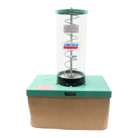
The chassis lube pump is electrically operated and used in
a progressive type centralized lubrication system. The
pump consists of a pump housing, electric gear motor, a
timer and a plastic reservoir with stirring paddle. The high
operating pressure allows the pump to supply lubricant up
to NLGI #2 grease.
MOUNTING THE PUMP
Select an easily accessible place of installation which allows
access to the timer and lubricant reservoir filler fitting. The
pump must be mounted vertically on an even surface by
means of three bolts. (See Fig. 1 on page 3.)
TOFILLRESERVOIR
Fill the reservoir through the grease fitting located at the
base of the reservoir, using a hand operated grease pump.
Refill reservoir when grease reaches “MIN” mark located on
the reservoir. Fill the reservoir up to the “MAX” mark
located on the reservoir.
TO PRIME SYSTEM
Pump & Supply Line: After reservoir has been filled with
recommended lubricant, loosen the supply line fitting.
Operate the pump until lubricant flows from outlet, then
tighten fitting.
Feed Lines: Pre-fill each feed line with lubricant before
connecting to outlet of divider valve and bearing.
NOV - 96
Models 94812, 94824
CHASSIS LUBE
ELECTRICGREASEPUMP
Series“A”


