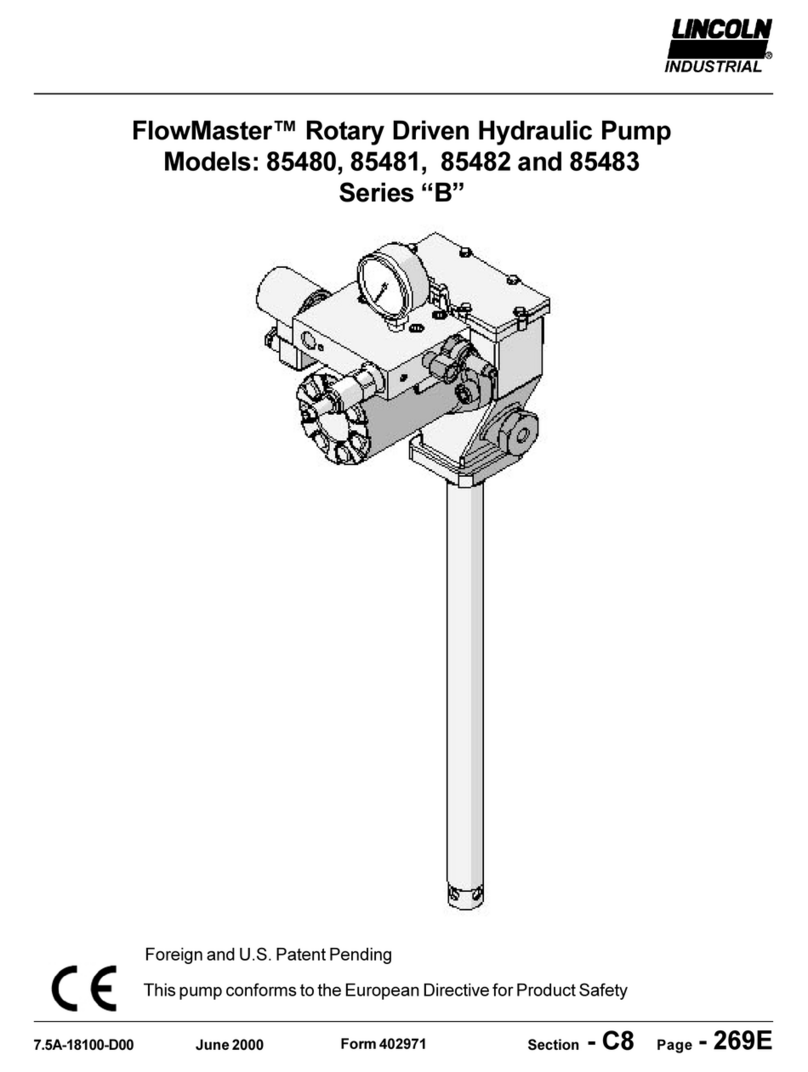
Lincoln industrial FlowMaster B Series User manual
Other Lincoln industrial Water Pump manuals

Lincoln industrial
Lincoln industrial CENTRO-MATIC A Series User manual

Lincoln industrial
Lincoln industrial 94822 User manual

Lincoln industrial
Lincoln industrial QUICKLUB 203 User manual

Lincoln industrial
Lincoln industrial A Series User manual

Lincoln industrial
Lincoln industrial QUICKLUB 203 User manual
Lincoln industrial
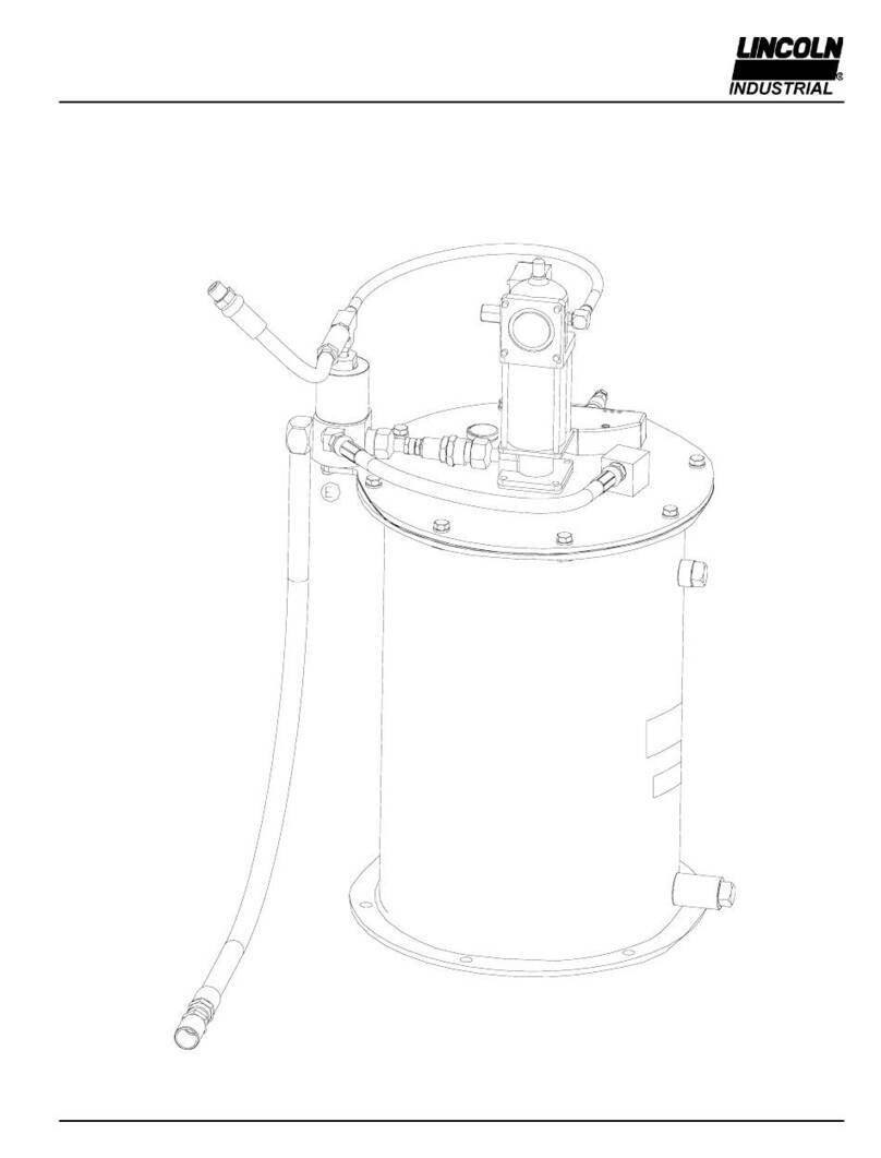
Lincoln industrial CENTRO-MATIC 85465 User manual

Lincoln industrial
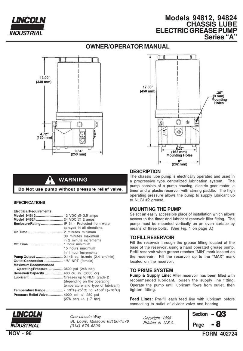
Lincoln industrial ZPU 75 User manual
Lincoln industrial
Lincoln industrial A Series User manual

Lincoln industrial
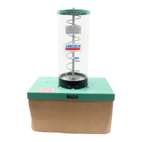
Lincoln industrial FlowMaster A Series User manual
Lincoln industrial
Lincoln industrial H Series User manual

Lincoln industrial
Lincoln industrial A Series User manual
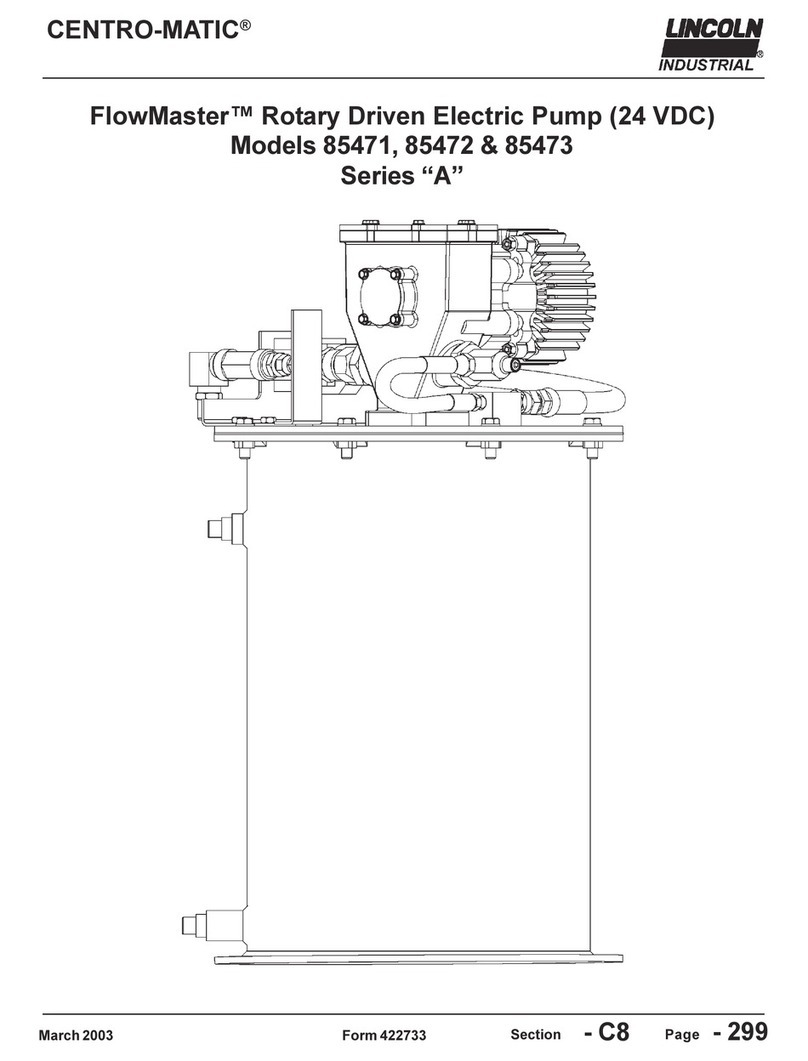
Lincoln industrial
Lincoln industrial CENTRO-MATIC FlowMaster A Series User manual

Lincoln industrial
Lincoln industrial FlowMaster A Series User manual

Lincoln industrial
Lincoln industrial 84960 User manual

Lincoln industrial
Lincoln industrial PP: User manual

Lincoln industrial
Lincoln industrial CENTRO-MATIC 85438 User manual

Lincoln industrial
Lincoln industrial CENTRO-MATIC 84050 User manual

Lincoln industrial
Lincoln industrial A Series User manual

Lincoln industrial
Lincoln industrial FlowMaster A Series User manual

Lincoln industrial
Lincoln industrial CENTRO-MATIC A Series User manual
Popular Water Pump manuals by other brands

Watershed Innovations
Watershed Innovations HYDRAPUMP SMART FLEX Instructional manual

Graco
Graco Modu-Flo AL-5M instructions

Messner
Messner MultiSystem MPF 3000 operating instructions

Xylem
Xylem Bell & Gossett WEHT0311M Installation, operation and maintenance instructions

WilTec
WilTec 50739 Operation manual

Franklin Electric
Franklin Electric Little Giant 555702 HRK-360S instruction sheet

Ingersoll-Rand
Ingersoll-Rand PD02P Series Operator's manual

VS
VS ZJ Series Operating instruction

Flotec
Flotec FPZS50RP owner's manual

SKF
SKF Lincoln FlowMaster II User and maintenance instructions

Xylem
Xylem Lowara LSB Series Installation, operation and maintenance instructions

Water
Water Duro Pumps DCJ500 Operating & installation instructions

Action
Action P490 Operating instructions & parts manual

Flo King
Flo King Permacore Reusable Carbon Bag Disassembly. & Cleaning Instructions

ARO
ARO ARO PD15P-X Operator's manual

Pumptec
Pumptec 112V Series Operating instructions and parts manual

Virax
Virax 262070 user manual

Neptun
Neptun NPHW 5500 operating instructions
