Lincoln DOUBLE User manual

LINCOLN TV BED
Page 1 of 13
DOUBLE:
KING:
221 x 149 x 126_87.5 (LWH_H)
301 x 164 x 126_87.5 (LWH_H)
140609

Warnings Assembly Ɵme: 1.5 Hours
x Before using the TV Lift, please read this instruction carefully
x Retain these instructions for future reference
x T ools are not included
x Strictly for indoor use
x Keep small parts out of reach of children
x T his product is intended for a maximum weight of 100kg per side (200kg combined)
x T his product should only be used on a level, firm floor
x T his product complies with the essential requirements of the EMC Directive 2004/108/EC and
Low Voltage Directive 2006/95/EC
x Keep away from temperatures over 35ºC
x Only use recommended accessories
Do
xWhen you are ready to start, make sure you have the right tools, plenty of space and a clean dry area
for assembly
x Check the pack and ensure you have all the parts listed
x Due to the size of the product we recommend is it assembled in the room intended for use
x Ensure the product is fully assembled as illustrated, before use
Make sure all the legs are in contact with the floor
x Regularly check all the fittings are tight & secure
xKeep this product away from open flames such as candles.
Please:
x DO NOT use power tools to assemble this product
x DO NOT over Ɵghten Įƫngs
x DO NOT stand or jump on the product
x DO NOT sit on the side rails
x DO NOT use the product if parts are missing or damaged
x DO NOT expose to direct sunlight, moisture or extreme temperatures.
x DO NOT expose this product to dripping or splashing, rain or areas with heavy moisture.
x DO NOT place any objects Įl led with liquids, such as vases, on the product.
x DO NOT place the product in direct sunlight or heat, such as radiators.
x DO NOT insert foreign objects into the product.
x DO NOT aƩempt to repair the mechanism by yourself - seek expert help.
x DO NOT exceed the weight limit
Safety and Care Advice
Page 2 of 13

Warnings - Electrical Components
Servicing is required when the unit has been
or plug is damaged, liquid has been spilled or objects have
the unit has been exposed to rain or moisture or unit does not operate normally
Do not expose the TV remote control and battery to excessive heat such as sunshine, fire or the like
Care Instructions
Wipe with a clean damp cloth. If there are any stubborn marks, use a non- abrasive
water
Do not use solvent based cleaners or detergents as they can bleach or damage the product
Never use scourers, abrasives or chemical cleaners
Safety and Care Advice
Unplug the unit during lightning storms or when unused for long periods of time
Where an appliance couple is used as the disconnect device, the disconnect device
shall remain readily operable
The unit should be powered off before plugging the product into the power outlet
This unit should be powered off before unplugging the product
Install this unit so that the power cord can be unplugged from the socket immediately
if any problems occur
Never try to repair this product yourself, take it to an authorized technician. Trying to
remove panels or repairing the unit yourself could result in an electric shock.
damaged in any way, such as power supply cord
fallen onto the unit,
sponge with warm soapy
Page 3 of 13

Parts Identification
Parts Checklist
1
2
3
4
5
6
7
8
9
10
11
Headboard
Footboard
Right Side Panel
Left Side Panel
Media Tray Base Panel
Media Tray Left Side Panel
Media Tray Back Panel
Media Tray Right Side Panel
1
1
1
1
1
1
1
1
Media Tray Support Legs 2
1
2
3
2
12
13
14
Centre Support Bar
Centre Leg
1
30/32
30/32
16
6
8
7
5
9
11
11
4
10
14
15
13
12
15 15/16
16
17
3mt Power Lead
4mt Aerial Lead HDMI Lead
17 18
18
1
19
2
3mt Power Lead
Cable Clip
19
Cable Tie
3
3
Wooden Slats (Double/King)
Single Plastic Cap (Double/King)
Double Plastic Cap (Double/King)
Cable Tie
4mt
Aerial Lead
2.8mt HDMI Lead
Cable Clip
Note: All cables and ties are in the accessory box
1
Page 4 of 13
Qty Qty
Ref. Description DescriptionRef.

Page 5 of 13
QtyCode Description
Ax26
Fittings Checklist
Bx16
Spring Washer
Cx28
Washer (17x8mm)
D
E
x13
Screw (5x50mm)
F
x1
Allen Key (5mm)
Additional Tools Required
x13
Barrel Nut
QtyCode Description
Intersecting
Hole
Crosshead Screwdriver We recommend the bed is
assembled in the room it will
be located in.
When they are supplied and are part
of the assembly of this bed, ensure
that barrel nuts are fitted the correct
way so the hole is facing towards the
intersecting hole.
x4
Screw-Washer set (M8) x1
Allen Key (5mm)
MN
TV INSTALLATION KIT
Hx4
Cable Clip
Cable Tie
x3
x3
K
L
x1
Allen Key (4mm)
x1
Allen Key (3mm)
(M6) x4
x4
Counter- Sunk Screw
(M4)
Counter- Sunk Screw
Bolts (M8x30mm) for
fitting side panel (3&4)
to headboard & footboard (1&2).
Bolts (M8x20mm) for
fitting leg (11) to centre
support bar (10)

Bed Assembly
Stage
1
Stage
1
Page 6 of 13
Ax20 Bx16 Cx24
Fit the bolts (A), spring washers (B), and flat washers (C) to the holes in the footboard (2) as shown.
Note: Do not fully locate the bolts, but leave 10mm protruding.
Fit the side panels (3 & 4) to the footboard locating the brackets behind the flat washers.
Fit the bolts (A), spring washers (B), and flat washers (C) through the brackets in the central set of holes.
Once all four corners are located, make sure the bed is square.
.
A
B
C
3
&
4
1
&
2
A
B
C
10mm
2
3
&
4
&
12
1
2
3
411
11
10
Hx4
11
10
E
C
Footboard
2
10
A
C
1
10
A
C
Headboard
Fix support legs to centre support bar (10), using the bolts (H)
and washer (C); fully tighten using Allen Key .
Push bolts (A) and flat washer (C),fixing centre support bar to
vely as shown - screw in the x4 bolts.
When all bolts are screwed in place, tighten them 100%.
Carefully adjust the feet (11) so support bar is supported evenly.
The holes for slats must point upwards
Ex1
headboard & footboard respecti
(E)
11
H

Stage
3
Bed
9
9
Ax2
Fit the support legs (9) to the underside of
the tray base panel using the bolts (A) to
secure. Fully tighten using the Allen Key (E).
Assembly
Page 7 of 13
Stage
2
7
7
6
8
5
Dx13 Fx13
Fit the barrel nuts (F), to the Media Tray back panel (7),
making sure the screw hole aligns with the intersecting
hole (see hints & tips section).
Fit the tray side panels (6& 8), to the back panel (7
)
using the screws (D) into the barrel nuts.
Fit barrel nuts (F) to the inside sides of the tray side
panels as shown.
Fit the tray base panel (5) using the screws (D) to
secure through into the barrel nuts previously fitted.
A
A

Page 8 of 13
Stage
4
Ax4 Cx4
Push bolt (A(rehsawhguorht) C),Hold tray firmly against side panel (4)
as shown and screw in x4 bolts. When all in place, tighten all bolts 100%.
Adjust the feet (G) so bottom of tray is level.
4
Bed
Assembly
It is important that after the initial fitting of your TV, all cables including aerial-HDMI-TVpower
and any auxiliary cables that you fit yourself, are securely positioned close to the back of the TV
using the cable clips & cable ties provided.
The cable clips & cable ties are provided for your safety and the safety of the equipment.
These are to prevent any entrapment of cables during the operating of the TV lift when it is moving
ineithertheupordownmode.Theyareprovidedtohelpyoumakecertainthatcablescannot
get trapped.
Route the cables in straight lines where possible; tie the cables together then fit the self-adhesive
cable clip close to back of the TV leading the cables down the duct on left or right side as
appropriate.
We cannot be held responsible for any damage to TV or damage to cabling due to poor cable
management and therefore cables getting trapped because they are not installed correctly.
After you have finished the installation, there should be no loose cables at all - push any excess
cable carefully back down the relevant duct.
The TV will automatically turn off when it lowers into the foot board, then on again when it rises up

TV Installation Instructions:
Before fixing the slats to the Bedstead, please follow the television installation instructions below:
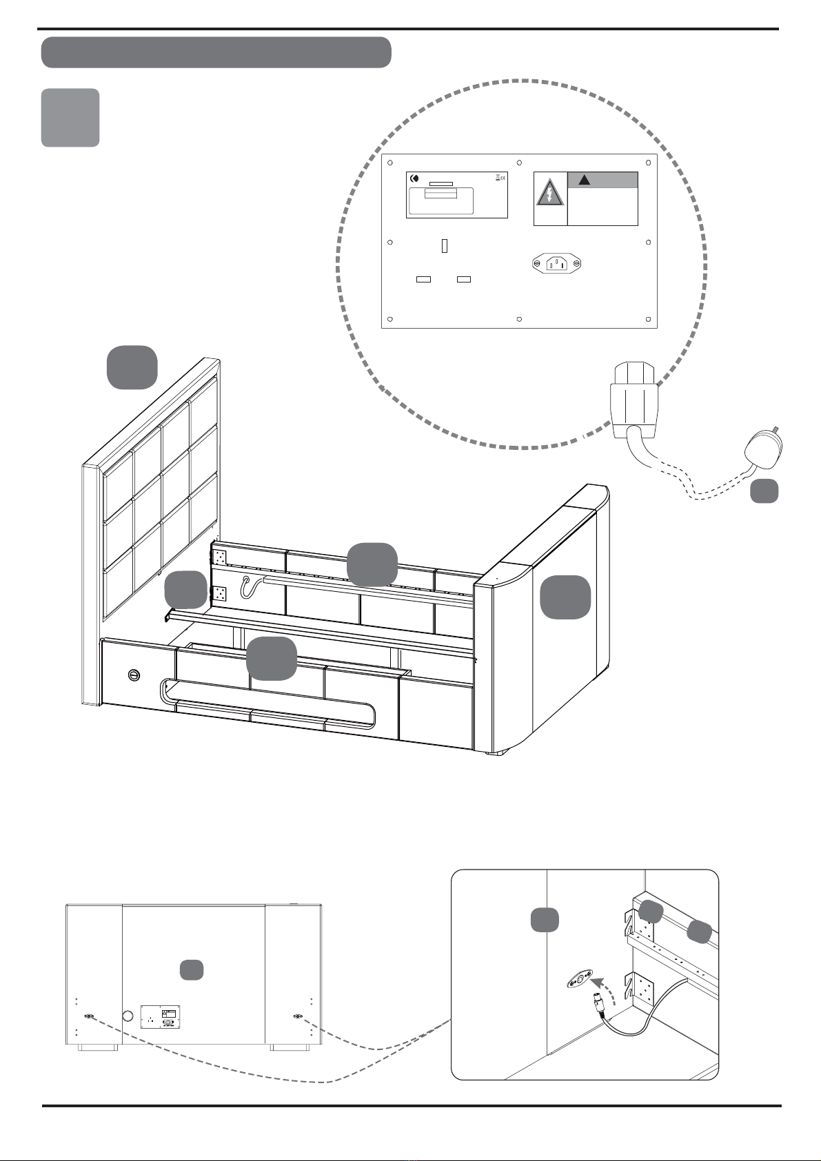
1. Connect the power lead (12) to the socket located at the bottom of the footboard (2) then connect to
the wall socket. The wall socket must of an earthed type for safety reasons. Connect media using the
x2 HDMI cables & the 4m aerial cable.
2. Raise the TV lift by pressing one of the UP buttons located on either side rail of the bed (TOP half of the
switch).
3. Unpack the television and if there are any TV mounting screws fitted, please remove them. Use the
screws supplied in the TV installation kit or those supplied with TV but make sure they are fitted
correctly. If your TV mounting is 100 x 100,removethe two brackets and use the cone shaped screws
throughbrackets into TV first, then re- fit the brackets with the thumb- screws.
4. If necessary you can adjust the bracket up and down to align with the screw fixing points, by
loosening the thumb screws on the back of the TV Lift and aligning the brackets with the
fixing holes.
5. Carefully tighten the screw ( M ) using the allen key ( N )-the screws & allen key can be
found in the TV Installation kit, in the main hardware pack inside the accessory box.
6. Connect the power and aerial cables to the television making sure the cables are not
loose. If necessary use cable ties & spare clips to route cables safely- carefully follow
main instructions in this guide.
7. The television can now be operated following the TV Operation Manual.
8. To lower the television back into the footboard, press one of the side panel DOWN
buttons (BOTTOM half of the switch). When DOWN button is pressed, TV will retract
into footboard and turn off automatically at the bottom.
9. When UP button is pressed- TV rises and turns itself back on automatically. Occasionally
you may need to press button twice..
Trouble shooting
1. If your television does not operate please check all the power connections, both to
the wall and to the socket in the footboard. Make sure TV is switched on. Note: TV
will only work when it is in the up position.
2. If the TV Lift does not operate, try each switch in turn. If neither switch operates press
the button twice. Check that the power to the controller is on.
3. If the television or TV Lift still fails to operate there may be a problem that can be
checked by our technicians. Call Customer Services for help and information (see
page 2).
IMPORTANT : Care should be taken when connecting electrical items.
Page 9 of 13

Stage
5
Page 10 of 13
FOOTBOARD
2
2
3
&
4
Connect the power cable (12) into the socket
located at the bottom of the footboard (2)
and then connect to your wall socket.
Note that the plug has an earth blade and the
wall socket must have an earth terminal too.
The plug connection must be easy to reach
if you need to disconnect the power.
On each side panel of the bed is a switch to
operate the TV Lift.
The switches are connected to the TV Lift by
a DIN plug on each side of the footboard - make
sure you plug them in properly - align the arrows
on the labels and push right in.
Switch DIN plug
Power Lead
AC 220V ~ 240V
!WARNING
HAZARDOUS VOLTAGE
Contact mav cause
electric shock or burn.
This unit is to be ser
trained personnel only.
viced by
!WARNING
HAZARDOUS VOLTAGE
Contactmav cause
electricshockor burn.
Thisunitis to be ser
trainedpersonnelonly.
viedby
12
T
MODEL: LINCOLN
POWER SUPPLY: AC 220-240V~50Hz
POWER CONSUMPTION:
S/N: 20140322
TV : MAX 56W
TV LEFT : 50W
Radio: 15W
CAUTION
RISK OF ELECTRIC SHOCK
DO NOT OPEN
CAUTION
TO REDUCE THE RISK OF ELECTRIC SHOCK.
DO NOT REMOVE COVER (OR BACK)
NO-USER SERVICEABLE PARTS INSIDE REFER
SERVICING TO QUALFIED SERVICE PERSONNEL MADE IN CHINA
POWER OUT
TO TV ONLY
POWER IN FROM
AN EARTHED WALL
SOCKET
4
2
3
10
1
BED ASSEMBLY

TV INSTALLATION KIT
BED ASSEMBLY
Stage
6
Page 11 of 13
PlatformPlatform
M
N
TELEVISION INSTALLATION
TV
HDMI 1
HDMI 2
Stage
7
CONNECT CABLES
18
17 Aerial Lead
HDMI Lead
17 18
16
Cable
Tie
19
Cable
Clip
N
x4
Screw-Washer set (M8/M6/M4)
x1
Allen Key (5mm/4mm/3mm)
M
N
This layout depends on the size
of TV that can be fitted and also
where the connections are on the
TV - please follow the suggestions
how to route cables.
TV mounting bracket - Max load is 20 kg.
Dimensions of TVs that can be fitted
to this TV lift:
Width 84 cm
Depth 5.5 cm
Height between 43 & 49.5 cm
Adjust the TV mounting brackets
up or down to suit your TV vesa
mounting holes. Keep bottom of
TV sitting on the platform.
Then adjust the upper bracket
so it sits just above your TV.
=
=
=

BED ASSEMBLY
Page 12 of 13
Stage
8
Aerial Lead
Aerial
Wall Socket
HDMI Leads
CONNECT CABLE
Take through the
cables from either
left or right duct.
18
18
17
AC 220V ~ 240V
!WARNING
HAZARDOUS VOLTAGE
Contact mav cause
electric shock or burn.
This unit is to be ser
trained personnel only.
vied by
T
MODEL: LINCOLN
POWER SUPPLY: AC 220-240V~50Hz
POWER CONSUMPTION:
S/N: 20140322
TV : MAX 56W
TV LEFT : 50W
Radio: 15W
CAUTION
RISK OF ELECTRIC SHOCK
DO NOT OPEN
CAUTION
TO REDUCE THE RISK OF ELECTRIC SHOCK.
DO NOT REMOVE COVER (OR BACK)
NO-USER SERVIC EABLE PARTS INSIDE REFER
SERVICING TO QUALFIED SERVICE PERSONNEL MADE IN CHINA
POWER OUT
TO TV ONLY
POWER IN FROM
AN EARTHED WALL
SOCKET
HDMI 1 & 2
Aerial Lead
17 18
HDMI 1 & 2
Aerial Lead
17 18
Use left or right duct,
depending on the ports
that are on your TV - take
the shortest route.
TV power cable.
supplied with your TV
TV power cable
supplied with your TV
TV power cable
supplied with your TV

Stage
10
3
13 14
14 13 13 15 13
Fix slat (13) to double plastic
cap (15). Fix single plastic caps (14)
Then connect onto centre support
bar (12) & metal support rails of side
panels (3 & 4) by tapping gently with
a light hammer.
9
on each end.
THE TV WILL AUTOMATICALLY TURN OFF WHEN IT LOWERS INTO THE FOOT BOARD,
THEN ON AGAIN WHEN IT RISES UP.
13
Page 13 of 13
BED ASSEMBLY
This manual suits for next models
1
Table of contents